Article

Structural Performance of a Precast Concrete Modular Beam Using Bolted Connecting Plates

1
Department of Architectural Engineering, Kyung Hee University, Deogyeong-Daero 1732, Yongin 17104, Korea
2
School of Architecture, Chosun University, 309 Pilmun-daero, Dong-gu, Gwangju 61452, Korea
*
Author to whom correspondence should be addressed.
Appl. Sci. 2021, 11(24), 12110; https://doi.org/10.3390/app112412110
Submission received: 28 October 2021 / Revised: 6 December 2021 / Accepted: 16 December 2021 / Published: 19 December 2021
(This article belongs to the Section Civil Engineering)

Abstract

:
In modular structures, prefabricated modular units are joined at the construction site. Modular structures must ensure splicing performance by connecting modular units sufficiently. The bolted connection using steel plates may suffer from alignment issues and corrosion problems. In a precast concrete (PC) modular system, there is difficulty grouting the sleeves when splicing reinforcing bars. This study proposed a PC modular beam using a bolted connecting plate to deal with issues in typical steel modules and PC modules. The structural performance was evaluated by flexural and shear tests on two monolithic beams and two proposed PC specimens. The test results showed that the structural performance of the PC modular specimen was 88% of that of the monolithic reinforced concrete (RC) beam specimen and 102% of the strength calculated by ACI 318-19. Therefore, the proposed PC modular system using bolted connecting plates can solve the problems observed in typical steel and PC modules and improve the structural performance.

1. Introduction

Prefabricated modules improve the speed of construction, efficiency of material usage, and worker safety, but they impose limits on construction, e.g., related to module size. Modular structures consist of modular units that are appropriately sized and are assembled on site. Structural performance and serviceability can be ensured if the modules are connected sufficiently. Therefore, studies have investigated connection methods between modular units to improve the stability and integrity of the modular structure. In the modular construction industry, both steel modules and concrete modules have been adopted with the connection method depending on the type of module. Steel modules weigh half as much as concrete modules and have advantages related to transportation and lifting. Concrete modules have benefits in terms of corrosion and seismic resistance. Welding is generally not used due to the need for skilled welders; instead, bolted connections are typically used on-site to assemble steel modular joints [1]. The connecting plates are attached at both ends of the modules and then are connected using bolts; this method may impose constraints on the arrangement of the modules, since the plates have to be connected to the modules externally [2]. Many studies have been conducted to propose bolted connections that place no constraints on the arrangement of modular units [3,4,5,6]. Chen et al. [2] proposed T-shaped beam-to-beam modular connections, which can ensure convenient installation and eliminate on-site welding. The components of this proposed connection method were a plug-in device and plate with welded stiffeners. The upper module and bottom module were assembled using the plug-in device and a plate connected by bolts. Chen et al. [2] confirmed that stiffeners can effectively increase the stiffness, but gaps would form between the upper and lower columns due to insertion of the plug-in device. These gaps influence the deformation patterns and bending moment distribution. Lee et al. [3] proposed a beam-to-beam bolted connection using a C-section beam. The connection plate was inserted between the upper and lower modular units, which consisted of a C-section beam fastened with bolts. The shape of the connection plate varies depending on whether it is being used on an inside, outside, or corner joint, so that the appropriate type can be used based on the placement of the modular units. Recently, studies have been conducted to suggest appropriate design methods that can consider a range of different connection types [7,8,9]. Li et al. [7] pointed out that connections for modular units are a relatively new structural form in comparison with traditional steel structures with fixed or flexible beam-to-column connections. Li et al. [7] proposed the governing equation for determining the effective length factor for connections between modular units. In the modular connection method, developed by previous researchers, steel plates used as the connection method between the modules are installed on the surface of each modular member using bolts. A large number of bolts are required for perfect bonding of the steel plate and the modular members, and a dense arrangement of bolts may cause damage to the modular members. In addition, connection using steel plates suffers from alignment issues and corrosion problems [1].
Unlike steel modules, precast concrete (PC) modules have reinforcing bars (rebars) inside each module, so connection between the rebars must be considered when the modules are connected. The rebars in the PC module are connected through a lap splice, welded splice, or grouted splice sleeve [10,11,12,13,14,15]. The grouted splice sleeve is the connection method used most widely. Two rebars are inserted into each sleeve and connected by pouring non-shrink, high-strength grouting material through grout ports. Yan et al. [13] conducted a cyclic loading test to investigate the seismic performance of precast concrete structures connected by grouted splice sleeve. Yan et el. [13] divided grout sleeves into two types; one was a full grout sleeve, which connected a sleeve and the rebar at both sides, and the other was a half grout sleeve, which is shorter than the full grouting sleeve and connects the sleeve and rebars through a screw thread at one side. Experimental results have shown that precast concrete structures have seismic performances similar to that of a monolithic structure, but there were differences in crack propagation, strain, and deformation of the joints. It has been confirmed that the length of grouting into splice sleeve and length of the cast-in-place region may affect the seismic behavior of a precast concrete structure. Recently, studies have focused on the behavior of precast structures under cyclic loading, because for these types of structures, seismic behavior may be different to that of cast-in-place RC structures [16,17,18].
Many studies have confirmed that the structural performance of PC modules connected by grouted splice sleeve is similar to that of monolithic structures. However, if the filling of grout mortar is insufficient, adequate capacity may not be ensured. Therefore, this study proposed a PC modular beam system that can improve on the disadvantages of the rebars’ connection method of the existing PC module. This system applies connecting plates, which are mainly used in steel modules, to the PC module to connect the rebars of each module. The main goal of the proposed connection method is to improve the construction difficulty in the existing connection method, which is used splice sleeve and joined horizontally. Table 1 shows a comparison between previous PC modules connected with steel plates and the proposed connection method. The purpose of proposed connection detail is to apply it to PC modular beams. In order to transfer bending and shear stress to module, it is designed considering the behavior of the beam. Figure 1 presents stress distribution in PC beams connected with the proposed method. The stress in one PC module can be transferred to the other PC module via connecting plates.
The proposed method has bolted connecting plates: a set of U-shaped and I-shaped plates. The I-shaped plate is inserted into the U-shaped plate and the two plates are connected using bolts. This method can accommodate alignment issues with the steel modules, allowing adjustment for unexpected construction errors. In addition, since the bolted connecting plate replaces rebar in the connection region, splice sleeves are not needed, avoiding problems caused by insufficient grouting on-site. The proposed connection method is for the connection between members where shear force and bending moment are mainly applied. Therefore, a flexural test and a shear test under monotonic load were conducted. Two monolithic reinforced concrete (RC) beam specimens and two PC modular beam specimens were manufactured. This paper assessed the applicability of the proposed PC modular beam to the provisions of American Concrete Institute (ACI 318-19) [19] based on the experimental results.

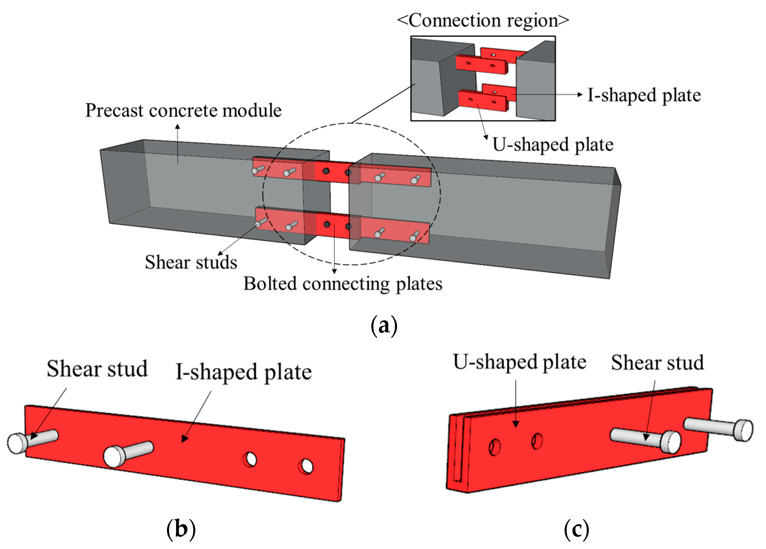
2. Concept of Modular Concrete Beam with Bolted Connecting Plates

In the typical PC modular beam using grouted splice sleeve, there was a possibility that the rebar was not positioned exactly at the center of the sleeve. As a result, the rebar was not fully grouted, and the full strength of the rebar could not be exploited. This study proposed a PC modular beam system using bolted connecting plates to improve the constructability of PC modular beams as shown in Figure 2. In a previous study [20], an L-shaped PC module with bolted connecting plate was proposed considering the role of a shear key in the PC module. However, construction difficulties were observed. The connection region was not fully grouted because of the module’s shape. To improve constructability, a new connection detail was proposed in this study. The PC module has a linear-shape to improve dealing with grouting problems that occurred in a previous study [20]. The proposed method is to connect the connecting plates protruding from each module and connect them using bolts. The bolted connecting plates consisted of a pair of U-shaped and I-shaped plates. The shear studs were welded to both ends of the bolted connecting plate to improve the bond capacity between the connecting plate and concrete. The module with the I-shaped plate was lifted and connected with the module with the U-shaped plate, reducing the construction time and on-site work required. In addition, the connecting plates were connected by bolting, which improves the splicing performance. After joining the connecting plates, non-shrink mortar was injected into the gap between the two PC modules. The non-shrink mortar used for bonding between modules was cheaper and had better fluidity than the epoxy adhesives used to fill the gaps between modules in the general PC modular method, allowing it to fill the connection region well. In addition, the construction costs can be saved.
The construction procedure for the proposed precast concrete modular beam system is shown in Figure 3. First, PC modules were assembled by connecting the U-shaped and I-shaped plates as shown in Figure 3a. As shown in Figure 3b, the connecting plates of the adjacent modules were joined by using bolts. Finally, the two modules were fully connected by injecting non-shrink mortar. Since this construction process is very simple compared to the construction process of the typical PC modular system, the proposed method is expected to improve constructability. In addition, the proposed method is expected to improve structural performance because construction errors can be reduced and integrity can be ensured.

3. Experimental Program

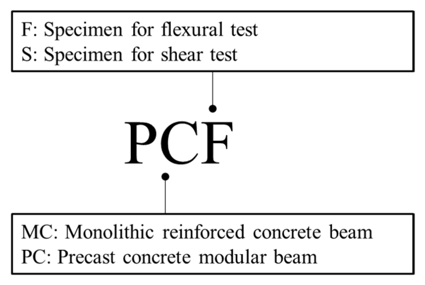
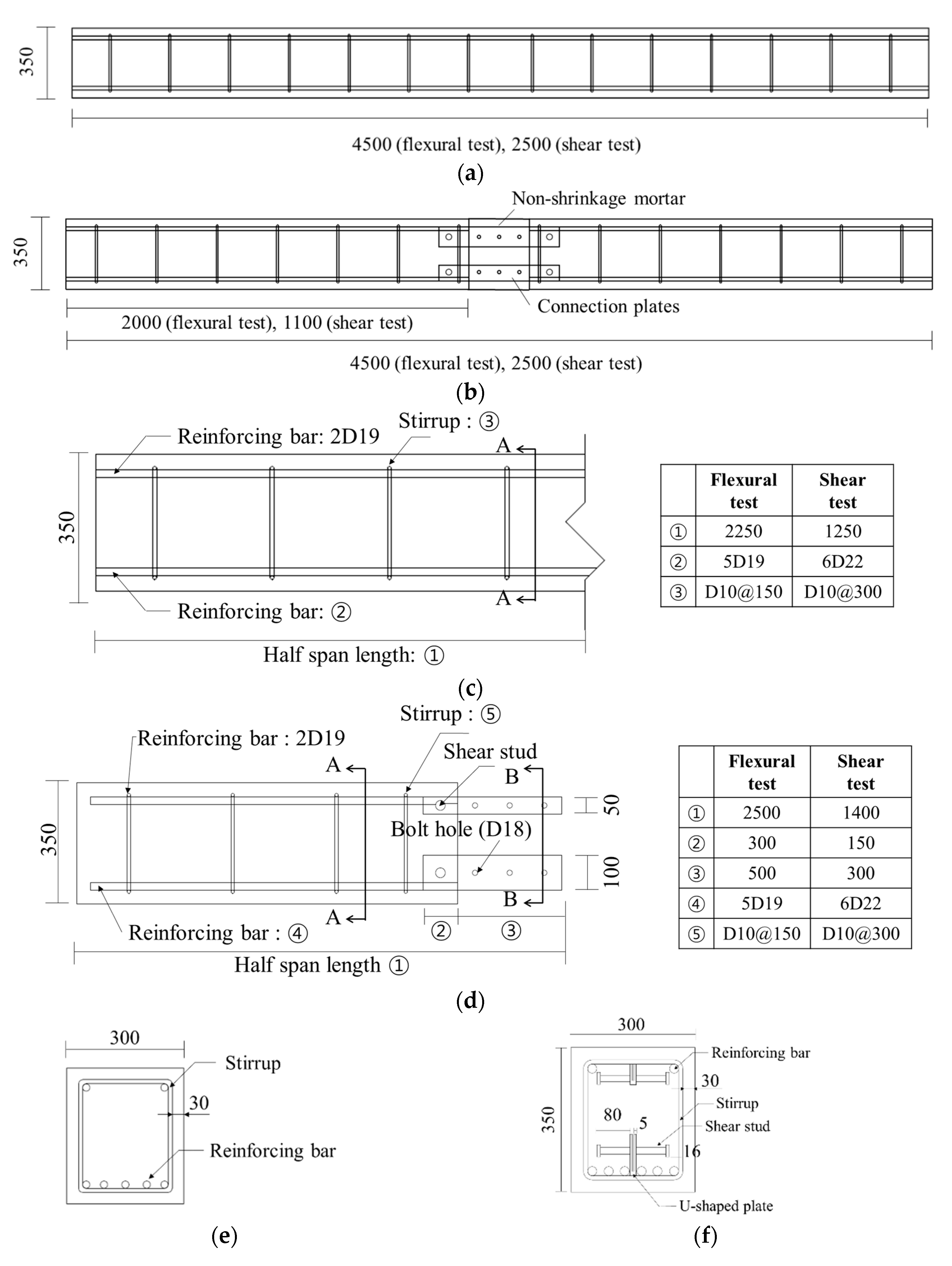
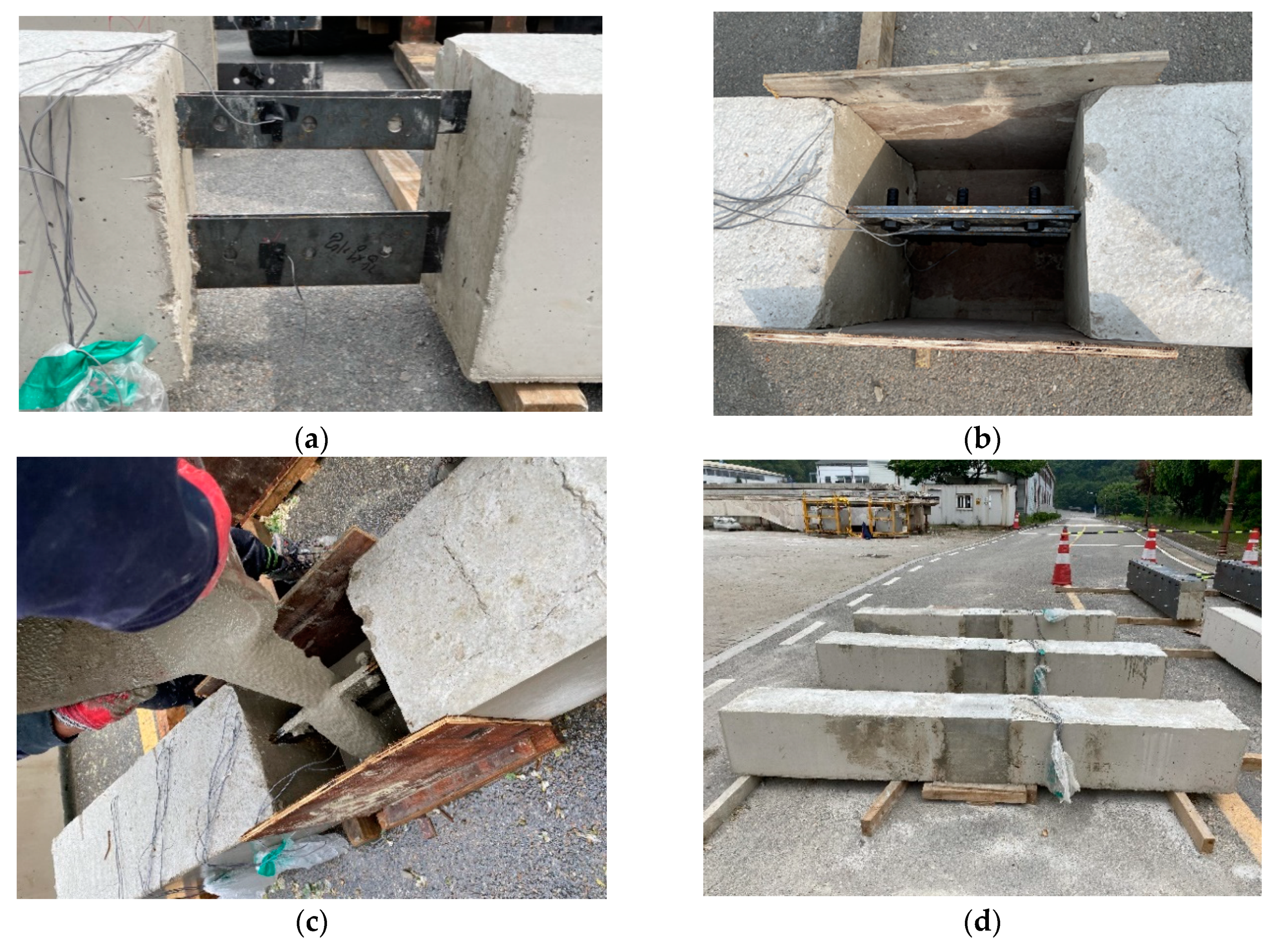
3.1. Specimen Details
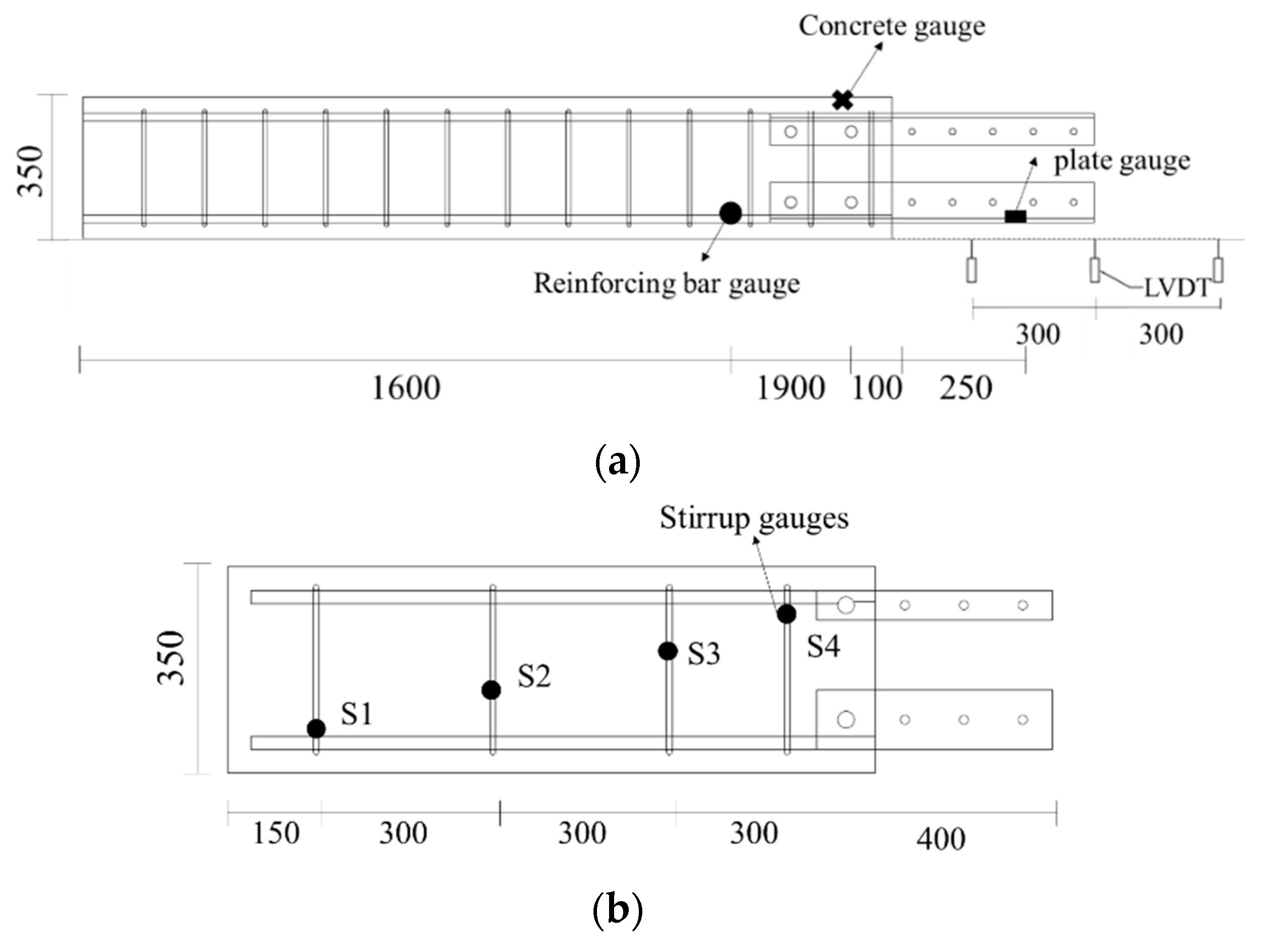
One of the primary issues for PC beams is how to resist shear forces rather than flexural capacity since PC is used in structures with a large cross-section in general. Therefore, while only the flexural test was conducted in the previous study [20], this study also investigated shear behavior. This paper considered that the splicing performance of the proposed method was sufficient if the PC modular beams showed a similar structural performance to that of a monolithic RC beam. Therefore, two RC beams and two PC modular beams were manufactured to evaluate structural performance. The notation of specimens is shown in Figure 4. The MCF and PCF specimens for the flexural tests were 300 mm in width and 350 mm in height with span lengths of 4500 mm. The reinforcement detail was designed according to the Korean Design Standard (KDS 14 20 50:2018) [21]. When conducting the flexural test, stirrups with a diameter of 10 mm were arranged at 150 mm spacings to prevent shear failure of the beams. The MCS and PCS specimens for the shears test had the same section as the specimens for the flexural test and span lengths of 2400 mm. Six rebars with a diameter of 22 mm were used to prevent flexural failure before shear failure. Based on the midspan, both modules are designed to have the same amount of steel plate as the steel reinforcement. The upper connecting plate and the lower connecting plate had the same amount of compressive reinforcement and tensile reinforcement. The size of the connecting plate depended on the amount of steel reinforcement. The thickness of the connecting plate was 5 mm, which is the most widely used, and the length was 800 mm for the flexural test specimen and 400 mm for the shear test specimen. The embedment length of the connecting plates was determined as provided in KDS 14 20 52:2021 [22] due to the prevention of pull-out failure. It is specified that the embedment length should be at least 150 mm in KDS 14 20 52: 2021 [22]; thus, the embedment length of the connecting plates in PCF and PCS were 300 and 150 mm, respectively. Drawings of the specimens are presented in Figure 5. The material properties were measured according to Korean standards [23,24,25]. The compressive strength of concrete was measured according to KS F 2405 [23], the compressive strength of non-shrink mortar was measured according to KS L 5105 [24], and the yield strength of rebars and steel for connecting plates were measured according to KS B 0802 [25]. Korean standards specify that the material properties can be determined from the average of the test results of three or more specimens; thus, this study manufactured three specimens for every material, and their properties were evaluated. The details of specimens are summarized in Table 2. The material properties in Table 2 are mean values. Figure 6 shows the procedure used to construct the PC modular beams. As shown in Figure 6a, PC modules were transported to the site and the U-shaped plate and I-shaped plate were connected by bolting as shown in Figure 6b. After the connection of the plates, non-shrink mortar was injected into the connection region as shown in Figure 6c. Before injecting non-shrink mortar, concrete chipping was employed in order to increase adherence to smooth surfaces. The form was removed when the compressive strength of the non-shrink mortar had reached the design compressive strength, 60 MPa, as confirmed by a uniaxial compression test.

3.2. Test Setup

Flexural tests and shear tests were conducted to investigate the structural performance and splicing performance of the PC modular beam with bolted connecting plates. The loading was applied to specimens with simply supported conditions at a rate of 2 mm/min using a hydraulic universal testing machine (UTM) with a capacity of 5000 kN. For beams with a shear span-to-depth ratio between approximately 2.5 and approximately 6, failure occurs at the shear cracking load, and for beams with a shear span-to-depth ratio greater than approximately 6, failure occurs in flexure prior to the formation of shear cracks [26,27,28]. Therefore, specimens for flexural and shear tests have shear span-to-depth ratios of 6 and 3, respectively. The test setup is shown in Figure 7. Many studies that focused on the investigation of shear behavior have conducted the shear test as shown in Figure 7b [29,30,31]. This shear test setup was to apply the same shear force in the same direction to the connection region. To monitor the strain of concrete, rebars or stirrups, and connecting plate of each specimen, strain gauges were attached as shown in Figure 8.

4. Experimental Results and Analysis

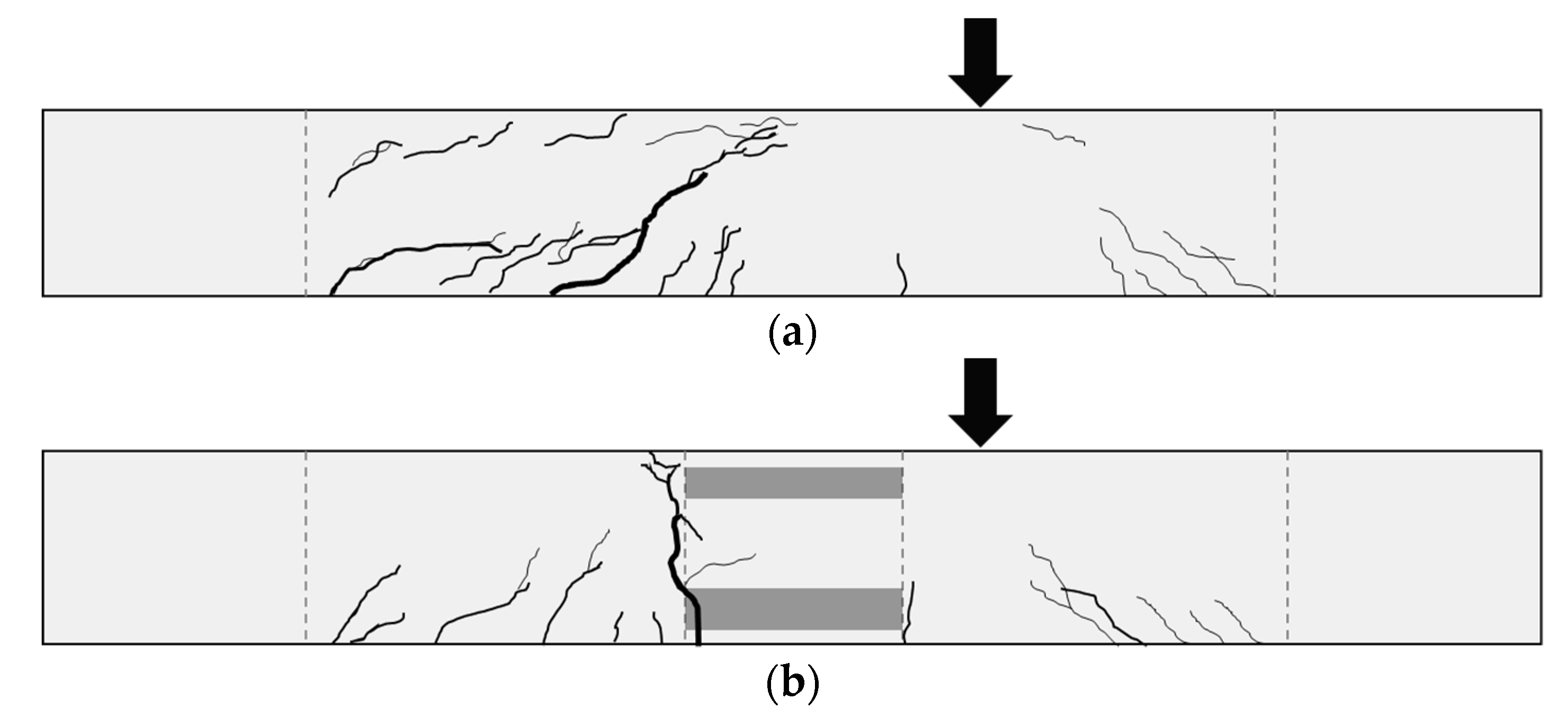
4.1. Crack Propagation and Failure Modes

The cracks that appeared during the flexural tests are shown in Figure 9. In the MCF specimen, initial flexural cracks were observed when the load reached 80% of the maximum load. These cracks extended vertically toward the compression zone. In the PCF specimen, flexural cracks developed, and the cracks occurred at the bottom of the connection when the flexural load reached 90% of maximum load. After this, these cracks extended vertically into the compression zone of the beam, and failure occurred. In both specimens, tension failure was observed which initiates by yielding of rebars followed by crushing of concrete at the compression zone. The strain distribution of rebar will be introduced in detail in the load–strain relationship.
The cracks and failure modes of specimens for the shear tests are shown in Figure 10. In every specimen, the shear cracks extended from the support to the loading point, and shear failure occurred. The initial flexural cracks were observed in the monolithic specimen and the PC modular specimen when the loads reached 30% and 40% of the maximum load, respectively. As the shear load increased, shear cracks developed, and cracks were formed in the connection region of PCS. Afterward, when shear loading was 90% of the maximum load, shear cracks progressed to the compression zone of the beam, and then flexural–shear failure was observed in both specimens. According to much research on PC modular members, cracks generally progress along with the joint configuration [32,33]. In PCF and PCS specimens, the initial propagation of cracks was similar to that of monolithic beams, and the general structural behavior of a PC beam was observed. This indicated that the proposed method can be applied in construction sites. In addition, there was no large deformation and partial detachment on the connection region, and failure did not occur in a brittle manner. The similar crack pattern between the PC modular specimens and the monolithic specimens indicates that the stress can transfer between each module effectively [34,35]. In the PCF under flexural load, flexural cracks were observed in the tension zone of the midspan. However, In the PCS under shear load, the cracks were extended vertically along the connection region. This crack occurred at the interfaces between the precast concrete and the mortar. It was judged that these cracks did not affect the structural capacity, because they were not accompanied by a decrease in load or increase in displacement [36,37]. In addition, it was confirmed that the connection played a role in transferring the shear stresses based on the shear cracks observed in each module.

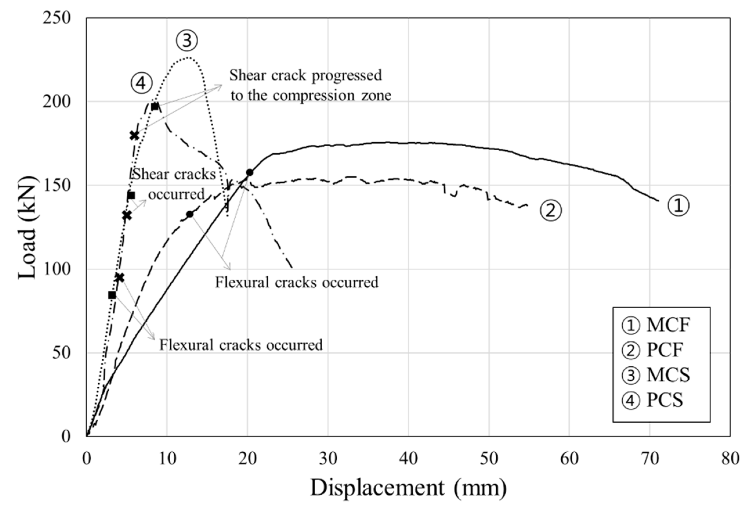
4.2. Load–Displacement Relationships

The test results are summarized in Table 3, and the load–displacement curves are illustrated in Figure 11. The maximum loads of the MCF and PCF specimens determined by the flexural tests were 175.65 and 155.13 kN, respectively. According to load–displacement curves, it was confirmed that the stiffness of the PCF was greater than that of the MCF in the elastic region. Therefore, as shown by the crack propagation, it can be confirmed that the occurrence of the flexural cracks was delayed in the PCF than in the MCF. The MCF specimen was a monolithic RC beam manufactured from concrete with a compressive strength of 24 MPa, but in the PCF, high-strength non-shrink mortar with a compressive strength of 60 MPa was injected into the gap between modules. Therefore, the PCF can resist deformation more easily than the MCF. In addition, the splicing performance of the PCF was confirmed, because there was no region where the stiffness decreased before the maximum load was reached.
In the shear tests, the maximum loads of the MCS and PCS were 226.25 kN and 200.96 kN, respectively. The stiffness of the two specimens was similar in the elastic region. In the flexural test, the PCF specimen showed greater initial stiffness than the MCF specimen, because the connection region resisted most of the flexural load in the pure bending area. However, in the shear test, the stiffness contribution of the joint was not observed, because the connection and concrete module resisted the shear load together. Unlike the PCS, the stiffness of the MCS decreased until reaching the maximum load after the elastic region. This is because the shear cracks in the support progressed to the compression zone as the shear load increased, and numerous cracks developed in the concrete as shown in Figure 10. In addition, the bolted connecting plate in PCS effectively resisted the shear force, so the stiffness did not decrease until the maximum load. After reaching the maximum load, the load decreased more gently than in MCS, so it is considered that the bolted connecting plate had better ductility. Accordingly, the proposed PC modular beams demonstrated similar capacity as the monolithic RC beams. These results show good agreement with previous studies, which demonstrated that PC modular members performed at 70–85% of the capacity of general RC monolithic members [38,39]. In addition, the flexural test results were compared to the previous study [20] that proposed the L-shaped PC module and connecting plate. The proposed method of this study had 1.1 times the flexural capacity compared to that of the previous study [20]. This can be attributed to the aspect that the proposed PC modular beam in this study was a linear-shaped module, so the gap between the PC modules could be completely filled with non-shrink mortar, unlike in the previous study [20]. It was demonstrated that the splicing performance of a PC modular beam was affected more by the bolted connecting plate than by the geometrical characteristics of the PC modules.

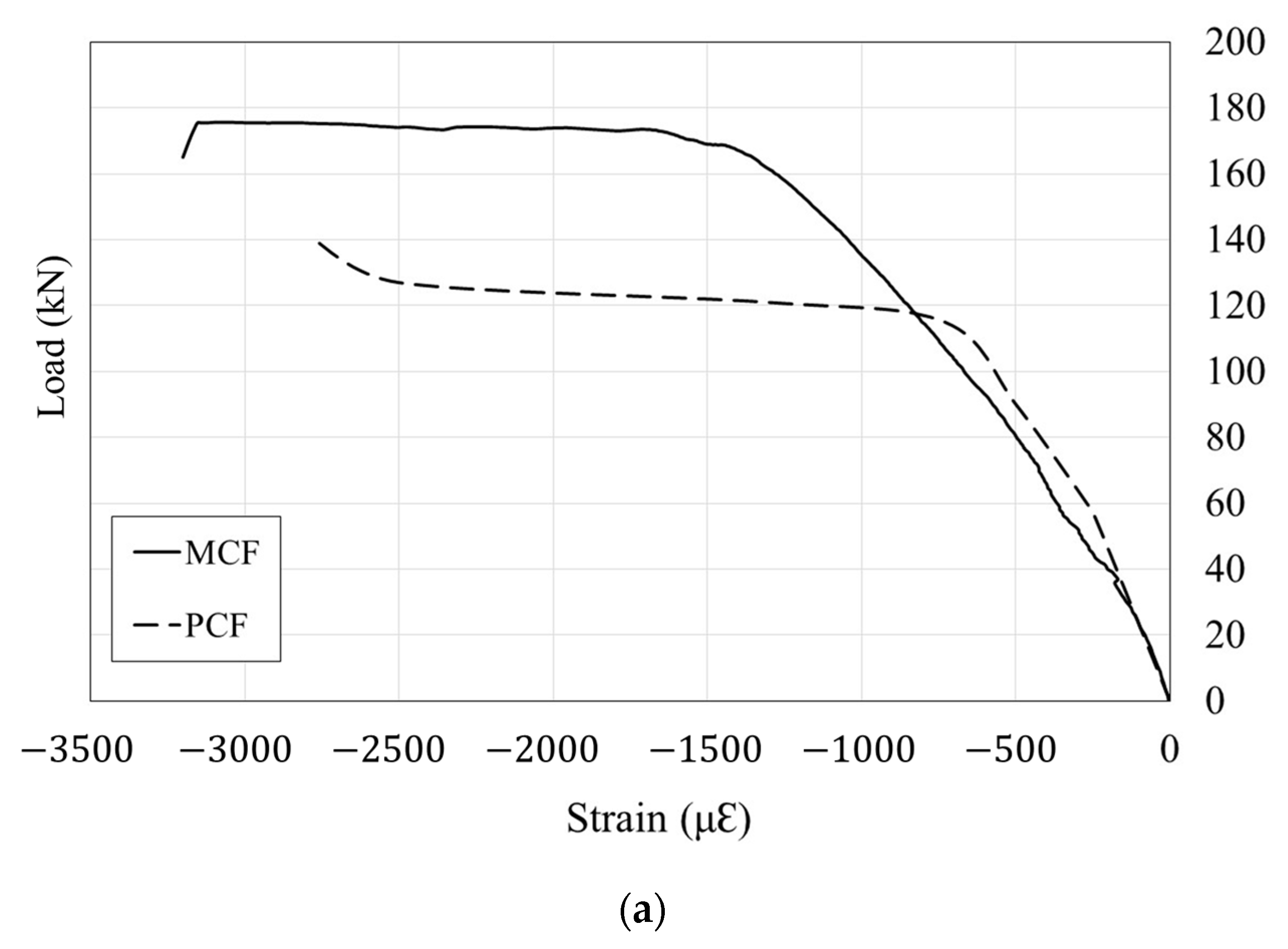
4.3. Load–Strain Behavior

To investigate the flexural behavior of the test specimen, the strain of concrete, rebar, and connecting plate were analyzed as shown in Figure 12. In the MCF specimen, it was confirmed that the strain of the concrete reached the ultimate compressive strain, 0.003. In the PCF specimen, the strain at failure was not measured because the concrete gauge was damaged. It was considered that the concrete reached ultimate strain because the concrete in the compressive zone was crushed. In addition, it was confirmed that the concrete strain distributions of the MCF and PCF were similar with increasing load. The rebar reached the yield strain of 0.002 in both specimens. It was indicated that the rebar effectively resisted tensile strength and splicing performance was confirmed. According to Figure 12b, tension failure occurred in both specimens due to the yielding of the rebar. The tension failure is a desired failure type in the beam design process. The bolted connecting plate inserted into the PC module exceeded the yield strain of 0.00138. Therefore, the stress between each PC module was transferred effectively through the joint, indicating that this component could resist the tensile strength as well.
To evaluate the shear behavior, the strain of the stirrup was analyzed as shown in Figure 13. The strain distributions are depicted in Figure 13 when the initial cracks occurred, cracks developed, and load reached approximately peak shear force. In the MCS and PCS specimens, the strain of the stirrup near the loading point, which is located 1050 mm from the end of the beam, increased the most rapidly, as they reached the maximum load; this stirrup yielded at the maximum load. In addition, it was confirmed that the strain of the stirrup located closer to the loading point was greater than that of the stirrup close to the support in both specimens. This is because, in RC beams, shear cracks progressed from the support to the loading point and, generally, strains show a rapid increase as the load approaches the peak shear resistance [40]. According to these results, it was confirmed that the bolted connecting plate could transfer stress to each PC module effectively. This means that corrosion did not occur due to the moisture penetration in the module and non-shrink mortar filled the connecting region tightly. Therefore, it was indicated that the PC modular method using the bolted connecting plate can ameliorate corrosion problems that occur in typical steel modules and difficulties related to injection into grouted splice sleeves used in typical PC module methods.

4.4. Evaluation of the Applicability of Design Code

For modular structures, a design guideline that can consider the characteristics of connection between modules should be proposed [7,8,9]. In the modular members which are connected with steel plates, the structural performance depends on connection length, embedment length, and amount of steel plates. Therefore, the steel plate should be considered when designing modular members. In this paper, the embedment length was considered to prevent pull-out failure, and it was determined as provided in KDS 14 20 52:2021 [22]. As per the test results, pull-out failure did not occur. In addition, connection length and the amount of steel were designed so that both modules had the same amount of steel reinforcement based on the midspan. Therefore, the flexural and shear strengths were calculated according to ACI 318-19 [19] without considering the contribution of connecting plates. The purpose of reinforcements in the compression zone was to provide support for the stirrups. Therefore, the number of reinforcements in the compression zone were fewer than the number of reinforcements in the tensile zone. The bending strength was calculated, neglecting the contribution of compression reinforcements. The design of the flexural and shear strengths of the RC beam presented in ACI 318-19 [19] are as follows:
M n , A C I = { A s f y ( d d ) + ( A s A s ) f y ( d a 2 ) }
V n , A C I = ( V c + V s )
V c = λ 6 f c b w d
V s = A v f y s d
where is the strength reduction factor, A s is the area of compression reinforcement, A s is the area of non-prestressed longitudinal tension reinforcement, f y is the yield strength for non-prestressed reinforcement, d is the distance from extreme compression fiber to centroid of longitudinal tension reinforcement, d is the distance from extreme compression fiber to the centroid of longitudinal compression reinforcement, a is the depth of the equivalent rectangular stress block, λ is the modification factor, b w is the web width, and A v is the area of shear reinforcement within spacing, s .
The experimental results showed that the moment of the MCF and PCF were 153.42 and 135.3 kNm, respectively, and they were approximately 114% and 101% of the design moment strength calculated through ACI 318-19 code. The shear strength of the MCS and PCS were 113.13 and 100.48 kN, respectively, and they were about 116% and 103% of the design shear strength of ACI 318-19. It was indicated that the proposed PC modular method met the requirements of the current design code, ACI 318-19 [19], and the PC modular beam had a similar performance capacity to a general monolithic RC beam. Furthermore, since the flexural and shear capacity of the PC modular beam exceeded the design strength, as a result of the comparison, the structural capacity of the PC modular beam using the proposed connection method can be estimated reasonably by using a current design code without any consideration of connecting plates. It was indicated that the steel plate did not contribute to enhancing strength, but it did act to transfer stress from each module. Therefore, if a steel plate connection is applied for the purpose of stress transfer, it is judged that the ACI 318-19 code can be used. In addition, it was confirmed that the connection method using a bolted connecting plate can solve the problems observed in typical PC modular beams using grouted splice sleeves wherein the full strength of a member could not be exploited because the sleeve was not fully grouted.

5. Conclusions

This paper proposed a PC modular system using bolted connecting plates to replace the grouted splice sleeves used in typical PC modules and simplify the construction process. To evaluate structural performance, monolithic RC beam and PC beam specimens were manufactured, and flexural and shear tests were conducted. The main conclusions of the study are as follows:
(1)
The flexural test indicated that initial flexural cracks occurred in the midspan of both the monolithic RC beam (MCF specimen) and the PC beam with a bolted connecting plate (PCF specimen). In the shear test, the shear cracks extended from the support to the loading point. In every PC modular specimen, cracks developed at the bottom of the connection as the load increased, and these cracks propagated along with the connection to the compression zone and failure occurred. The connection between the PC modules ensured splicing performance until the experiment was terminated, and brittle failure was not observed;
(2)
The maximum flexural and shear strengths of the PC modular beam using a bolted connecting plate were 88.3% and 88.8% of those of the monolithic RC beam, respectively. PC modular beam specimens ensured splicing performance because there was no region where the stiffness was decreased until reaching the maximum load, and the load decreased gently after reaching the maximum load;
(3)
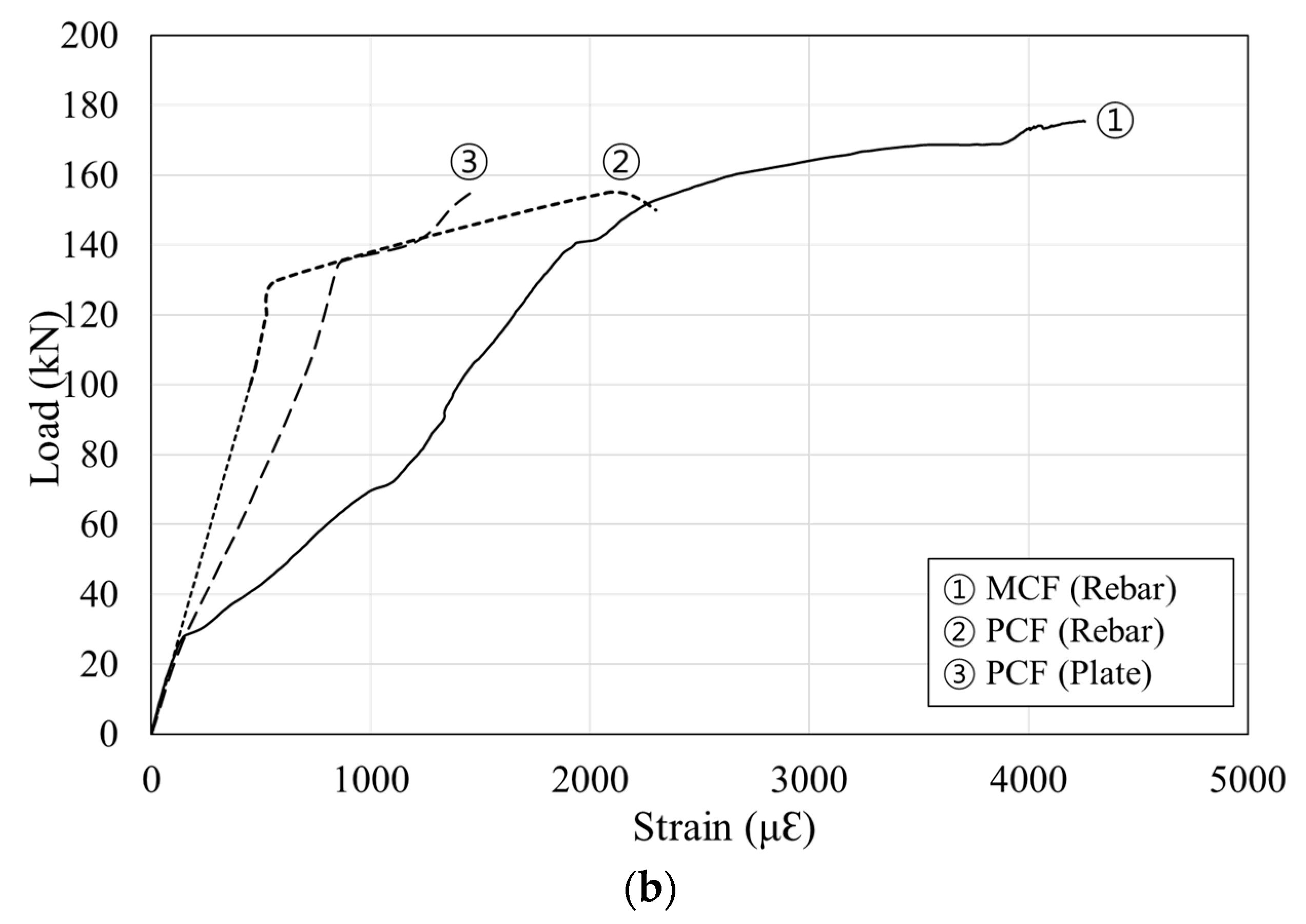
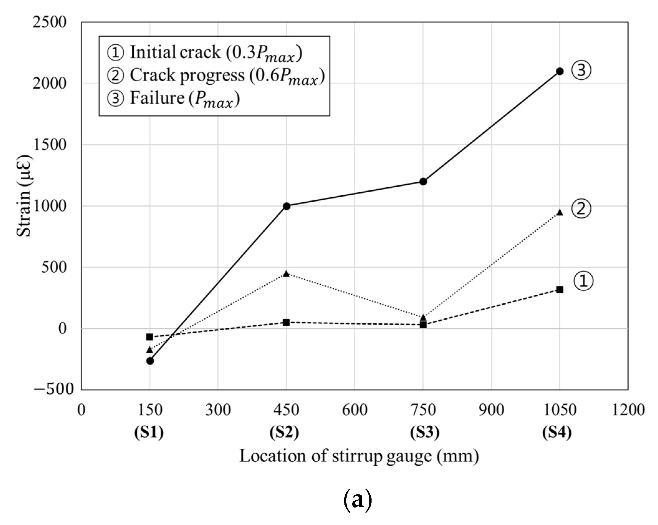
The flexural test indicated that the rebars of the MCF and PCF showed similar strain distributions as the load increased and exceeded yield strain near the maximum load. It was indicated that the rebar effectively resisted tensile stress. The bolted connecting plate inserted into the PC module exceeded the yield strain of 0.00138. The results of the shear test confirmed that the strain of the stirrup located closer to the loading point increased dramatically as with the RC monolithic beam. Therefore, the bolted connecting plate can transfer stress to each PC module effectively, showing excellent splicing performance, and it can deal with problems that may occur in typical modular structures;
(4)
The applicability of ACI 318-19 to the PC modular structure with a bolted connecting plate was evaluated. Experimental results showed that the maximum moment and shear strengths were approximately 101% and 103% of the design moment strength calculated through ACI 318-19. Thus, the proposed PC modular method meets the requirements of the current design code, such as ACI 318-19, and the PC modular beam performed similarly to the general monolithic RC beam. Therefore, the proposed method using a bolted connecting plate ensured splicing performance and had excellent structural performance.

Author Contributions

Conceptualization, K.M.R. and Y.H.L.; methodology, K.M.R.; validation, M.S.K. and C.G.C.; formal analysis, K.M.R.; investigation, M.S.K. and C.G.C.; writing—original draft preparation, K.M.R.; writing—review and editing, Y.H.L. All authors have read and agreed to the published version of the manuscript.

Funding

This research was supported by a National Research Foundation of Korea Grant (NRF-2019R1A4A1028116), funded by the Ministry of Education, Korea.

Institutional Review Board Statement

Not applicable.

Informed Consent Statement

Not applicable.

Data Availability Statement

Data sharing not applicable.

Conflicts of Interest

The authors declare no conflict of interest.

References

  1. Dai, Z.; Dai Pang, S.; Liew, J.R. Axial load resistance of grouted sleeve connection for modular construction. Thin-Walled Struct. 2020, 154, 106883. [Google Scholar] [CrossRef]
  2. Chen, Z.; Liu, J.; Yu, Y.; Zhou, C.; Yan, R. Experimental study of an innovative modular steel building connection. J. Constr. Steel Res. 2017, 139, 69–82. [Google Scholar] [CrossRef]
  3. Lee, S.; Park, J.; Shon, S.; Kang, C. Seismic performance evaluation of the ceiling-bracket-type modular joint with various bracket parameters. J. Constr. Steel Res. 2018, 150, 298–325. [Google Scholar] [CrossRef]
  4. Lacey, A.W.; Chen, W.; Hao, H.; Bi, K.; Tallowin, F.J. Shear behaviour of post-tensioned inter-module connection for modular steel buildings. J. Constr. Steel Res. 2019, 162, 105707. [Google Scholar] [CrossRef]
  5. Wang, Y.; Xia, J.; Ma, R.; Xu, B.; Wang, T. Experimental study on the flexural behavior of an innovative modular steel building connection with installed bolts in the columns. Appl. Sci. 2019, 9, 3468. [Google Scholar] [CrossRef] [Green Version]
  6. Khan, K.; Yan, J.B. Finite element analysis on seismic behaviour of novel joint in prefabricated modular steel building. Int. J. Steel Struct. 2020, 20, 752–765. [Google Scholar] [CrossRef]
  7. Li, G.Q.; Cao, K.; Lu, Y.; Jiang, J. Effective length factor of columns in non-sway modular steel buildings. Adv. Steel Constr. 2017, 13, 412–426. [Google Scholar]
  8. Chua, Y.S.; Liew, J.R.; Pang, S.D. Modelling of connections and lateral behavior of high-rise modular steel buildings. J. Constr. Steel Res. 2020, 166, 105901. [Google Scholar] [CrossRef]
  9. Lacey, A.W.; Chen, W.; Hao, H.; Bi, K. Review of bolted inter-module connections in modular steel buildings. J. Build. Eng. 2019, 23, 207–219. [Google Scholar] [CrossRef]
  10. Rodríguez, M.E.; Torres-Matos, M. Seismic behavior of a type of welded precast concrete beam-column connection. PCI J. 2013, 58, 81–94. [Google Scholar] [CrossRef]
  11. Park, J.; Choi, J.; Jang, Y.; Park, S.K.; Hong, S. An experimental and analytical study on the deflection behavior of precast concrete beams with joints. Appl. Sci. 2017, 7, 1198. [Google Scholar] [CrossRef] [Green Version]
  12. Kuang, Z.; Zheng, G. Computational and experimental mechanical modelling of a composite grouted splice sleeve connector system. Materials 2018, 11, 306. [Google Scholar] [CrossRef] [PubMed] [Green Version]
  13. Yan, Q.; Chen, T.; Xie, Z. Seismic experimental study on a precast concrete beam-column connection with grout sleeves. Eng. Struct. 2018, 155, 330–344. [Google Scholar] [CrossRef]
  14. Haber, Z.B.; Graybeal, B.A. Lap-spliced rebar connections with UHPC closures. J. Bridge Eng. 2018, 23, 04018028. [Google Scholar] [CrossRef]
  15. Lu, Z.; Huang, J.; Dai, S.; Liu, J.; Zhang, M. Experimental study on a precast beam-column joint with double grouted splice sleeves. Eng. Struct. 2019, 199, 109589. [Google Scholar] [CrossRef]
  16. Sousa, R.; Batalha, N.; Rodrigues, H. Numerical simulation of beam-to-column connections in precast reinforced concrete buildings using fibre-based frame models. Eng. Struct. 2020, 203, 109845. [Google Scholar] [CrossRef]
  17. Torquati, M.; Belleri, A.; Riva, P. Displacement-based seismic assessment for precast concrete frames with non-emulative connections. J. Earthq. Eng. 2020, 24, 1624–1651. [Google Scholar] [CrossRef]
  18. Meydanli Atalay, H.; Ozden, S. Cyclic Behavior of Beam-Column Connections in Precast Structures. Front. Built Environ. 2021, 7, 639778. [Google Scholar] [CrossRef]
  19. ACI Committee 318. Building Code Requirements for Reinforced Concrete and Commentary (ACI 318-19); American Concrete Institute: Farmington Hills, MI, USA, 2019. [Google Scholar]
  20. Ro, K.M.; Kim, M.S.; Cho, C.G.; Lee, Y.H. An Experimental Study on the Flexural Behavior of Precast Concrete Modular Beam Systems Using Inserted Steel Plates. Appl. Sci. 2021, 11, 3931. [Google Scholar] [CrossRef]
  21. KDS 14 20 50. Design Specification of Reinforcement Detail for Concrete Structure; Korea Costruction Standards Center: Seoul, Korea, 2018. [Google Scholar]
  22. KDS 14 20 52. Design Specification of Anchorage and Splices for Concrete Structure; Korea Costruction Standards Center: Seoul, Korea, 2021. [Google Scholar]
  23. KS F 2405. Method of Test for Compressive Strength of Concrete; Korea Standards Association: Seoul, Korea, 2017. [Google Scholar]
  24. KS L 5105. Testing Method for Compressive Strength of Hydraulic Cement Mortar; Korea Standards Association: Seoul, Korea, 2017. [Google Scholar]
  25. KS B 0802. Method of Tensile Test for Metallic Materials; Korea Standards Association: Seoul, Korea, 2013. [Google Scholar]
  26. MacGregor, J.G.; Wight, J.K.; Teng, S.; Irawan, P. Reinforced Concrete: Mechanics and Design, 4th ed.; Prentice Hall: Upper Saddle River, NJ, USA, 1997. [Google Scholar]
  27. Abdelkarim, O.I.; Ahmed, E.A.; Mohamed, H.M.; Benmokrane, B. Flexural strength and serviceability evaluation of concrete beams reinforced with deformed GFRP bars. Eng. Struct. 2019, 186, 282–296. [Google Scholar] [CrossRef]
  28. Liu, C.; Wang, X.; Shi, J.; Liu, L.; Wu, Z. Experimental study on the flexural behavior of RC beams strengthened with prestressed BFRP laminates. Eng. Struct. 2021, 233, 111801. [Google Scholar] [CrossRef]
  29. Bousselham, A.; Chaallal, O. Effect of transverse steel and shear span on the performance of RC beams strengthened in shear with CFRP. Compos. Part B Eng. 2006, 37, 37–46. [Google Scholar] [CrossRef]
  30. Hu, B.; Wu, Y.F. Effect of shear span-to-depth ratio on shear strength components of RC beams. Eng. Struct. 2018, 168, 770–783. [Google Scholar] [CrossRef]
  31. Moradi, E.; Naderpour, H.; Kheyroddin, A. An experimental approach for shear strengthening of RC beams using a proposed technique by embedded through-section FRP sheets. Compos. Struct. 2020, 238, 111988. [Google Scholar] [CrossRef]
  32. Kankeri, P.; Prakash, S.S. Experimental evaluation of bonded overlay and NSM GFRP bar strengthening on flexural behavior of precast prestressed hollow core slabs. Eng. Struct. 2016, 120, 49–57. [Google Scholar] [CrossRef]
  33. Hussein, H.H.; Sargand, S.M.; Al Rikabi, F.T.; Steinberg, E.P. Laboratory evaluation of ultrahigh-performance concrete shear key for prestressed adjacent precast concrete box girder bridges. J. Bridge Eng. 2017, 22, 04016113. [Google Scholar] [CrossRef]
  34. Parastesh, H.; Hajirasouliha, I.; Ramezani, R. A new ductile moment-resisting connection for precast concrete frames in seismic regions: An experimental investigation. Eng. Struct. 2014, 70, 144–157. [Google Scholar] [CrossRef]
  35. Lu, C.; Dong, B.; Pan, J.; Shan, Q.; Hanif, A.; Yin, W. An investigation on the behavior of a new connection for precast structures under reverse cyclic loading. Eng. Struct. 2018, 169, 131–140. [Google Scholar] [CrossRef]
  36. Guan, D.; Guo, Z.; Xiao, Q.; Zheng, Y. Experimental study of a new beam-to-column connection for precast concrete frames under reversal cyclic loading. Adv. Struct. Eng. 2016, 19, 529–545. [Google Scholar] [CrossRef]
  37. Zhang, J.; Ding, C.; Rong, X.; Yang, H.; Wang, K.; Zhang, B. Experimental seismic study of precast hybrid SFC/RC beam–column connections with different connection details. Eng. Struct. 2020, 208, 110295. [Google Scholar] [CrossRef]
  38. Kim, M.S.; Lee, Y.H. Structural behavior of spliced post-tensioned girders with precast box segments. Int. J. Concr. Struct. Mater. 2019, 13, 21. [Google Scholar] [CrossRef]
  39. Breccolotti, M.; Gentile, S.; Tommasini, M.; Materazzi, A.L.; Bonfigli, M.F.; Pasqualini, B.; Gianesini, M. Beam-column joints in continuous RC frames: Comparison between cast-in-situ and precast solutions. Eng. Struct. 2016, 127, 129–144. [Google Scholar] [CrossRef]
  40. Wu, Y.F.; Hu, B. Shear strength components in reinforced concrete members. J. Struct. Eng. 2017, 143, 04017092. [Google Scholar] [CrossRef]
Figure 1. Stress distribution in the proposed connection method.
Applsci 11 12110 g001
Figure 2. Schematic of the proposed precast concrete modular beam using a bolted connecting plate: (a) front view; (b) I-shaped plate; (c) U-shaped plate.
Applsci 11 12110 g002
Figure 3. Construction process of the proposed precast concrete modular beam system: (a) connection between U-shaped and I-shaped steel plates; (b) bolted connection between plates; (c) injection of non-shrink mortar.
Applsci 11 12110 g003
Figure 4. Notation of specimens.
Applsci 11 12110 g004
Figure 5. Drawings of the specimens for flexural and shear tests (mm): (a) monolithic specimens; (b) PC modular specimens; (c) sideview of monolithic beam specimens; (d) sideview of precast concrete modular specimens; (e) A-A section; (f) B-B section.
Applsci 11 12110 g005
Figure 6. Process of construction: (a) assembling connecting plates; (b) bolting between connecting plates; (c) injection of non-shrink mortar. (d) Removal of concrete form.
Applsci 11 12110 g006
Figure 7. Test setup: (a) schematic of the test setup for flexural test; (b) schematic of the test setup for shear test.
Applsci 11 12110 g007
Figure 8. Location of gauges (mm): (a) the locations of gauges for the flexural test; (b) the locations of gauges for the shear test.
Applsci 11 12110 g008
Figure 9. Crack propagation of flexural test specimens: (a) MCF; (b) PCF.
Applsci 11 12110 g009
Figure 10. Crack propagation of shear test specimens: (a) MCS; (b) PCS.
Applsci 11 12110 g010
Figure 11. Load–displacement curves.
Applsci 11 12110 g011
Figure 12. Strains of flexural test specimens: (a) strain of concrete; (b) strain of rebars and plate.
Applsci 11 12110 g012aApplsci 11 12110 g012b
Figure 13. Strains of shear test specimens: (a) strain of stirrup in MCS; (b) strain of stirrup in PCS.
Applsci 11 12110 g013aApplsci 11 12110 g013b
Table 1. Comparison between the existing type of connection and the proposed method.
Type of ConnectionConnecting Mechanism between PC ModulesCharacteristics
Connected using splice sleeve Applsci 11 12110 i001
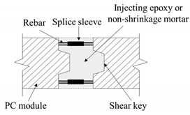
The rebars in PC modules are connected through splice sleeves;
If the filling of grout mortar is insufficient, adequate capacity may not be ensured.
Existing connection method joined vertically Applsci 11 12110 i002
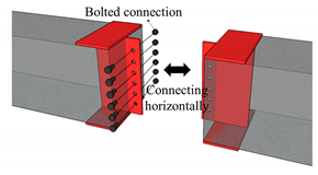
Steel plates with the same height as the cross-section are inserted into the PC modules and are horizontally connected;
It is uneconomical because a large quantity of steel is needed;
An unexpected construction error is not allowed.
Proposed connecting plate Applsci 11 12110 i003
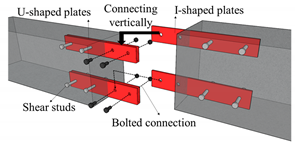
The proposed method of this study consists of U-shaped and I-shaped steel plates, which can be vertically connected in a lifted state;
It is economical because a steel plate is designed with the same amount of rebar as a monolithic beam;
It can adjust for unexpected construction errors based on geometric characteristics
Table 2. Details of specimens.
SpecimenExperimentTypeDimension ( b × h × l ,   mm ) Material Property (MPa)
Concrete ( f c ) Non-Shrinkage Mortar ( f c ) Deformed Steel ( f y ) Steel Plate ( f y )
MCFFlexuralMonolithic 300 × 350 × 4500 23.3-405.3-
PCFModular60.5269.8
MCSShearMonolithic 300 × 350 × 2400 --
PCSModular60.5269.8
Table 3. Summary of the test results.
Specimen P m a x   ( kN ) δ u 1   ( mm ) M e x p 2   ( kNm ) V e x p 3   ( kN )
MCF175.6537.55153.42N/A
PCF155.1332.54135.3N/A
MCS226.2512.70N/A113.13
PCS200.968.21N/A100.48
δ u 1 : The displacement when the maximum load is applied. M e x p 2 : The bending moment of each specimen. V e x p 3 : The shear strength of each specimen.
Publisher’s Note: MDPI stays neutral with regard to jurisdictional claims in published maps and institutional affiliations.

