Abstract
This paper presents studies on the dynamic analysis of the ASPIRE robot, which was designed for the medical recovery of brachial monoparesis. It starts from the virtual model of the existing version of the ASPIRE robot, which is analysed kinematically and dynamically by numerical simulations using the MSC.ADAMS software. For this purpose, this paper presents theoretical aspects regarding the kinematics and dynamics of the markers attached to the flexible bodies built in a specifically developed MSC.ADAMS model. Three simulation hypotheses are considered: (a) rigid kinematic elements without friction in couplings, (b) rigid kinematic elements with friction in couplings, and (c) kinematic elements as deformable solids with friction in couplings. Experimental results obtained by using the physical prototype of ASPIRE are presented. Results such as the connecting forces in the kinematic joints and the torques necessary to operate the ASPIRE robot modules have been obtained by dynamic simulation in MSC.ADAMS and compared with those determined experimentally. The comparison shows that the allure of the variation curve of the moment obtained by simulation is similar to that obtained experimentally. The difference between the maximum experimental value and that obtained by simulation is less than 1%. A finite element analysis (FEA) of the structurally optimized flexion/extension robot module is performed. The results demonstrate the operational safety of the ASPIRE robot, which is structurally capable of supporting the stresses to which it is subjected.
1. Introduction
One of the most important factors of global interest is maintaining quality of life in the coming years by increasing life expectancy [1]. Globally, the leading cause of long-term disability in adults is stroke or spinal cord injury [2,3]. Stroke is the second leading cause of death, with an incidence of 11.8%, after ischemic heart disease, with an incidence of 14.8% [4]. The most common consequences that can occur after a stroke are cognitive impairment (VCI), post-stroke fatigue (PSF) and post-stroke depression (PSD) [5]. In more than 85% of cases, stroke causes upper limb injuries, [6] and only in 10% of cases, the subjects regain arm mobility [7]. Strokes can cause pure brachial monoparesis, which supposes partial paralysis of the upper limb, an unusual cerebrovascular syndrome that can be misdiagnosed due to the lack of any other neurological deficits. Few reports in the literature adequately describe the syndrome or provide a substantial clinical or anatomical correlation [8,9]. The main problem is the difficult recovery due to the complexity of the movement of the upper limbs [10]. The patient must follow a repetitive and task-oriented functional training [11], which translates into a high consumption of time and energy for therapists [12].
Issues of annual medical cost and stroke trends were discussed in [13]. In the US, the annual medical cost for stroke will increase up to 2.5 times in 2030 compared to 2012. In the UK, stroke is the fourth leading cause of death [14]. The annual cost of health and social care for patients with stroke is over 5 billion GBP [15,16]. Currently, in developed countries, 3–4% of health expenditures are dedicated to stroke cases [17].
The number of strokes in the elderly is increasing. In addition, the age of people suffering from stroke is decreasing, reaching 50 years or even 40 years, the medical cost for the treatment of post-stroke trauma is high, it requires expensive medical care and, in addition, the number of therapists able to provide physical training is low compared to the number of patients [18].
In recent decades, it has been shown that exoskeleton-based rehabilitation can be used as an alternative to regular manual therapy to improve motor function [19]. Studies on the development of robotic structures for medical rehabilitation of the lower limb and upper limb have been intensively developed in recent years [20,21,22,23,24,25,26,27,28,29,30]. A complex classification, taking into account defining criteria, of robotic devices for upper limb rehabilitation can be found in [31,32], while in [33], a review of the literature investigating upper body kinematics in people without disabilities through optical motion capture can be found.
Li J. et al. [34] propose a new 4-DOF upper limb exoskeleton that has an ergonomic design and is kinematically compatible with the upper limb. Culmer P.R. et al. [35] developed a novel system for quantitatively measuring arm movement. In order to obtain upper limb joint angles and torques, a series of data was analysed with respect to Cartesian and upper limb coordinate systems to better understand arm movement, in particular to objectively evaluate physical therapy treatments and support the development of robotic devices to facilitate upper limb rehabilitation. In [36], the authors studied the activity and fatigue of upper extremity muscles, pain levels, subject satisfaction levels, and number of repetitions in task-specific training compared with robot-assisted training in individuals post-stroke. The research [37] concluded that virtual or actual task-specific robot training (TSRT) performed with a robotic orthosis or a physical therapist significantly reduced arm impairments around the shoulder and elbow without significant gains in fine motor hand control, activities of daily living or independence.
The exoskeleton technology is evolving quickly but still needs research to solve technical challenges and kinematic compatibility and promote the development of effective human–robot interaction. In [38], researchers have addressed a design problem of an exoskeleton by applying cable transmission, which allows the exoskeleton to place the actuators at a fixed base.
Hamida et al. [39] proposed and applied a combined methodology to optimize a cable-driven parallel robot for upper limb rehabilitation exercises by minimizing the tensions in cable and achieving the smallest footprint. In [40], the authors presented a new mechanism for providing variable stiffness for a 4 DOFs robot used for upper limb rehabilitation.
ASPIRE [22] is a device designed as an innovative structure, a parallel robotic system with 3 DOFs based on a spherical architecture designed for upper limb rehabilitation. The main purpose of its design was to solve problems related to shoulder flexion/extension as well as adduction/abduction and pronation/supination of the forearm. Its kinematic structure and motion were presented in [23]. Studies related to how it worked in clinical trials can be found in [30,41]. In [41], the ASPIRE interchangeability was investigated with classical physiotherapy using quantitative electroencephalogram (EEG), motor driving times and turn/amplitude analysis. A significant effect of the therapy was found for various pathologies. Design optimization following clinical evaluation and clinician feedback was presented in [31]. After careful monitoring and analysis of the robotic system, significant differences were revealed compared to the initial laboratory tests performed on healthy subjects. An improved design was elaborated based on the critical characteristics of clinical trials.
The aim of this study is to analyze from a kinematic, dynamic and experimental point of view the ASPIRE robot for the medical recovery of brachial monoparesis. For this purpose, a dynamic simulation of the robot in the ADAMS virtual environment when a virtual patient for rehabilitation uses the robot will be performed. Three distinct situations will be studied:
- The kinematic elements will be considered as rigid bodies, and the friction in the kinematic couplings will not be considered;
- The kinematic elements will be considered as rigid bodies, and the friction in the robot couplings will be considered;
- Both the flexibility of the kinematic elements and the friction in the couplings will be considered.
Results obtained by numerical simulation will be compared with those obtained from MSC.ADAMS. Finally, a verification of the structural integrity of the flexion/extension module of the robot, which is subject to the highest mechanical stresses, will be performed.
2. Constructive and Functional Description of the ASPIRE Robot
ASPIRE is a parallel robotic system based on a spherical architecture dedicated to be used in rehabilitation and it is the subject of a patent [42]. The movements that the robot can perform are flexion-extension and adduction-abduction of the shoulder joint, as well as pronation-supination of the forearm joint with the help of a third motor. The main design feature of the robotic system consists of two circular guides that lead to a spherical motion of the characteristic point of the mechanism.
The robotic structure’s frame was built out of aluminum profiles, while the robot’s housing was made of Plexiglas. The sliding carriages were 3D printed and appropriately lubricated to maintain a low friction coefficient, and the circular guides were made of aluminum. The shoulder rest was also 3D printed to guarantee that the shoulder was supported throughout the flexion and extension movements. The forearm support was 3D printed and integrated into an adjustable mechanism to accommodate varying forearm lengths. The metal palm rest was integrated into the pronation/supination mechanism. The horizontal circular guide was connected to the vertical circular guide through a passive revolute joint between the circular guides. An actuated height adjustment mechanism was added to allow easy setup of the robot between patients of different heights. To make it easier to set up the robot between patients of different heights, an actuated height adjustment system was incorporated.
The kinematic scheme based on which the virtual and the experimental model is built is shown in Figure 1 [43]. As shown in the kinematic diagram, the ASPIRE robot is composed of two modules. The first module, framed by the green line border, is intended for the rehabilitation movement of the shoulder. The XOYZ Cartesian reference system (frame) is placed in the centre of the shoulder joint. By rotating the circular segment, G1, around the Z axis of the reference system, the adduction-abduction movement q1 is performed.
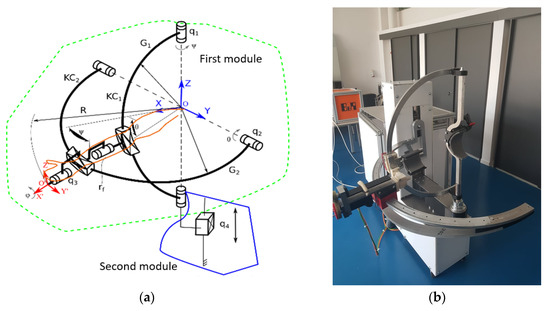
Figure 1.
(a) Kinematic scheme; (b) physical prototype of ASPIRE [43].
The flexion-extension movement q2 is performed by rotating the circular portion G2 around the Y axis of the same frame. The two circular portions G1 and G2 are connected by means of the passive kinematic coupling (rf), so that a spherical trajectory of the reference system O’X’Y’Z’ is obtained with respect to the point O, as shown in Figure 1b. The pronation-supination movement is defined by the q3 coordinate. The second module allows the vertical adjustment of the rehabilitation mechanism so that, with the help of a screw-nut system, the translation movement q4 is performed.
3. Theoretical Aspects Regarding the Kinematic and Dynamic Analysis of the ASPIRE Robot in MSC.ADAMS
For the dynamic study of the robotic systems, the most used software is MSC.ADAMS [44], due to the accuracy of results obtained. Thus, the use of this software in various research fields in the industry is noticeable, among which can be mentioned exoskeleton robotic systems or flexible robotic units for minimally invasive surgery [45,46,47,48,49,50,51,52]. MSC.ADAMS uses the kinematics of markers in three essential areas: kinematics, dynamics and optimization of mobile mechanical systems. Marker kinematics deals with the study of the position, orientation, velocity and acceleration of markers [53].
The instantaneous position vector of a marker that is attached to a node, noted P, on a flexible body is the sum of three vectors (Figure 2).
where is the position vector of the origin of the local reference system with the origin in B, attached to the flexible body, relative to the origin of fixed reference system, G; represents the position vector of the point P in the initial position on the undeformed body in relation to the local reference system attached to the flexible body; and is the position vector of the point P’, the new position of P on the deformed body, in relation to the initial position of the point P.
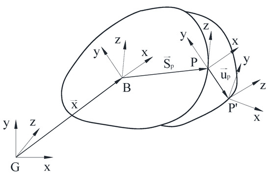
Figure 2.
The position vector of the point of a deformed flexible body relative to a reference system attached to the flexible body and the fixed base G.
We write Equation (1) in a matrix form expressed in relation to the basic coordinate system:
where [] is matrix associated with the position vector , having as elements the generalized coordinates , and of the origin B of the system associated with the flexible body.
[] is a matrix associated with the position vector having as elements the constant coordinates of the point P in relation to the local system of the body.
[] is the transformation matrix from the local reference system in B to the basic system, G, being composed of cosine directors of the origin of the local reference system in relation to the fixed one. The orientation is calculated using Euler’s angles, , and , which are used to define the generalized coordinates of the flexible body.
[] is a matrix associated with the position vector of point P’ with respect to P, expressed by coordinates related to the local coordinates system attached to the body. Matrix [] can be written:
where is the portion of the form function matrix that corresponds to the translation degrees of freedom of the node , being a matrix type, where is the number of form functions. Coordinates of form functions , also represent the generalized coordinates of the flexible body.
Therefore, the complete matrix form of the generalized coordinates of the flexible body is:
3.1. Velocities
To calculate the kinetic energy, the instantaneous translation velocity of the point in relation to the global reference system, which is obtained by differentiating the relationship Equation (2) with respect to time, has been computed, resulting in:
Considering the property of the vector product of two matrices, of which the matrix is antisymmetric:
it can be written:
where is the matrix of the angular velocity of the body relative to the fixed system (expressed in the coordinates of the body).
Replacing Equation (7) in Equation (5) results in:
where:
representing the relationship that makes the connection between the angular velocity and the derivative in relation to the time of the orientation state.
3.2. Angular Velocities
To meet the angular constraints, the markers orientation of a flexible body during deformation is instantly evaluated. As the body deforms, the marker rotates at relatively small angles to the reference frame. Like translational deformations, these angles are obtained using a modal overlap, similar to Equation (3),
where is the part of form functions matrix that corresponds to the degrees of freedom of rotation of the node . The matrix size of is , where is the number of form functions.
The marker orientation in relation to the base is represented by the Euler transformation matrix, . This matrix is the product of the three transformation matrices:
where is the matrix for transforming the coordinates from the local reference system attached in B to the body to basic or global coordinates; is the transformation matrix during the change of orientation by deforming the flexible body of the pole P coordinates in relation to the local reference system attached to the body; and is the constant transformation matrix, defined by the user when placing the marker J on the flexible body.
Matrix is defined by the cosine directors of a vector with small angles, :
where the sign ~ represents the antisymmetric operator.
3.3. Angular Velocities
The angular velocity of a marker, , of a flexible body is the sum of the angular velocities of the body and the angular velocities during deformation:
The equations governing a flexible body are derived from Lagrange’s equations:
where is the Lagrangian, defined by the relationship , where and represents the kinetic and potential energy, respectively; represents the energy dissipation function, defined by the relationship:
represents the constraint equations; represents Lagrange’s multipliers for constraints; represents the generalized coordinates defined in the relationships Equation (4); represents the generalized applied forces (applied forces projected on ); and [D] represents the damping matrix.
The velocity in relation to Equation (5) can be expressed in terms of the derivative with respect to time of the state vector, .
The kinetic energy for a flexible body is given by:
where and are the nodal mass matrix and the nodal inertia tensor of the node .
is sometimes a negligible amount, as, for example, bars, beams, housings are used in the model with flexible components.
By substituting and and simplifying, we obtain the kinetic energy in the generalized coordinates and the matrix of the generalized masses.
For clarity of presentation, the matrix of generalized masses is partitioned into , in block matrices 3 × 3 in size.
where indices , and represent the translation, rotation and modal degrees of freedom, respectively.
The expression for the mass matrix simplifies to an expression in 9 inertia invariants:
The explicit dependence of the mass matrix on the modal coordinates is obvious. The dependence on the orientation coordinates of the system is due to the transformation matrices A and B. Inertia invariants are calculated from the N nodes of the finite element model based on information about each node , its undeformed location , and its participation in the components of form functions . The discrete shape of the inertia components is provided in Table 1.

Table 1.
The discrete shape of the inertia components.
Position and orientation constraints for flexible body markers are satisfied using the kinematic properties of the previously presented markers.
The final form of the differential equations of motion is:
where , , and are the matrices associated with the generalized coordinates of the flexible body and their derivatives with respect to the time; represents the flexible body mass matrix; and represents the derivative with respect to time of the flexible body mass matrix.
4. Dynamic Analysis of the ASPIRE Robot Using MSC.ADAMS Software
In this paragraph, by using MSC.ADAMS [44] a software frequently used for numerical simulations in scientific researches [45,46,47,48,49,50,51,52], the virtual dynamic analysis of the ASPIRE robot when used by a virtual patient who needs to rehabilitate the movements of the upper limb is performed. The aim of this analysis is to determine the external loads of the kinematic elements of the ASPIRE robot. These loads will be the input data to perform structural analysis of the robot elements with the ANSYS finite element analysis program. A virtual model of the ASPIRE robot assembly—a human virtual mannequin that respects the average anthropometric dimensions of the sample of human subjects considered in the experimental tests, namely a mass of 72 kg and a height of 1.68 m—has been made in Solid Works. The patient is incorporated into the design of the robotic structure, and the center of the sphere, which is defined by two circular guides, is put in the center of the patient’s shoulder, allowing for full arm motion while undergoing shoulder rehabilitation. The targeted motions of the ASPIRE robot are:
- Shoulder flexion/extension (±45 degrees);
- Shoulder adduction/abduction (±45 degrees);
- Forearm pronation/supination (±45 degrees).
Figure 3 shows the assembly of the dummy together with the ASPIRE robot and the performed motions relevant for rehabilitation.
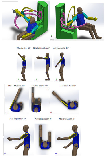
Figure 3.
ASPIRE robot assembly—virtual mannequin in neutral position in Solid Works.
The geometric model of the robot assembly was imported into MSC.ADAMS, specifying the mechanical characteristics of the material of each element of the robot so that, based on these properties, the MSC.ADAMS software could calculate the mass, inertial properties and position of the centre of mass of each component. The kinematic joints of the robot were defined, as shown in Figure 4.
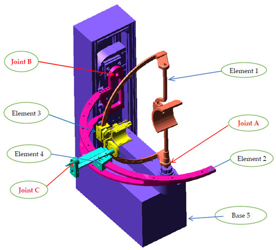
Figure 4.
Model of the ASPIRE robot transferred to ADAMS.
Elements 1 and 2 are connected to the base by joints A and B, respectively. For these couplings, we will present the connection forces and moments as calculated using the MSC.ADAMS program. A rotational joint is defined between elements 3 and 4, as shown in Figure 4. Element 3 (yellow) slides on the circular portion of element 1 by means of a guidance system.
For a correct simulation of the contact between elements 3 and 4 and the circular portions of elements 1 and 2, the contact of 2 points on the load arm of element 3 on the circular guidance system of element 1 was defined, as shown in Figure 5. The dynamic model is finalized taking into account this aspect, namely the contact between the elements running on the circular portions of the multi-body model, as well as the external forces given by the weight of the upper limb. For the dynamic analysis, we joined the dummy’s arm with the mounting brackets of the forearm and the human arm. The WSTIFF solver and the SI2 integration algorithm were used to solve the dynamic model.
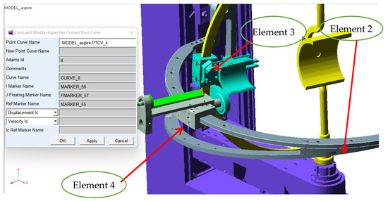
Figure 5.
Defining the contact (by point-on-curve coupling) between slide 4 and the circular guide 2.
All three modules, the extension flexion module, the adduction/abduction module as well as the pronation/supination module, are geometrically shaped and have defined material properties, which allows us to calculate the inertial properties and their masses.
Regarding the dummy used in the virtual simulation, the mass of the upper limb segments are as follows: 0.52 kg for hand weight and 160 mm length, 1.52 kg for forearm weight with 240 mm length and 2.63 kg for upper arm weight with 260 mm length. The patient position in the MSC.ADAMS virtual simulation is shown in Figure 6.
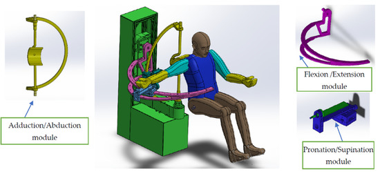
Figure 6.
ASPIRE robot modules.
4.1. Dynamic Analysis in MSC.ADAMS of the Robot, Considering the Kinematic Elements as Rigid Solids
In order to analyze the dynamic behavior of the robot/mannequin assembly, harmonic laws of motion of the form: 0.4 × cos (1 × time), with an amplitude of 45 degrees and the period of 6.3 s were defined for the drive motors of each module. The time variation graph for the law of motion of the motors performing the rehabilitation movements is presented in Figure 7. In MSC.ADAMS, the implemented law of motion is defined as MOTION_1 or MOTION_2 for the second module, and in Figure 7, a measurement of the angle from the motor joint has been made. These parameters that define the amplitude and period of the movement were chosen because the laws of motion that will be done in the numerical simulation must be similar to the movement recommended for rehabilitation prescribed by the physiotherapist.
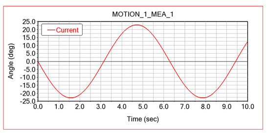
Figure 7.
Law of motion imposed in ADAMS on robot motor joints.
A dynamic simulation was performed for the situation when the robotic system is used by the virtual patient dummy and all three modules of the ASPIRE robot are active simultaneously (flexion/extension, abduction/adduction, pronation/supination). The simulation was performed for a period of 20 s. Figure 8 shows the extreme operating positions of the ASPIRE robot corresponding to the situation when the flexion/extension and abduction/adduction movements are active, indicating a combined movement. The trajectories described by the elbow and shoulder joints are observed, which are spatial (spherical) circular portions.
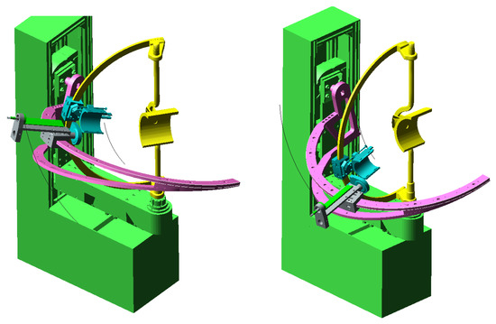
Figure 8.
Extreme operating positions of the ASPIRE robot corresponding to a combined flexion-extension and abduction-adduction movement.
In the first phase, a dynamic simulation with the specified laws of motion, without taking into account the friction in the kinematic joints of the robot, was performed. The results obtained for this simulation, meaning the variations of the motor moment calculated by numerical simulation in ADAMS when simultaneously performing those three types of movement—flexion-extension, adduction-abduction and pronation-supination of the arm—are presented in Figure 9.
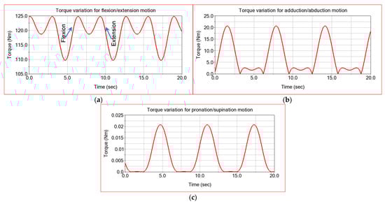
Figure 9.
ADAMS simulation computed torque for: (a) the flexion-extension module; (b) the adduction-abduction module; (c) the pronation-supination module.
It is observed that the maximum value of the actuation moment of the flexion/extension module reaches a maximum value of 125 Nm, and the minimum is 110 Nm. It is important to note that these results are obtained when all three modules are active simultaneously.
For the adduction-abduction movement, the motor moment obtained by numerical simulation in ADAMS is presented in Figure 9a. It is observed that its amplitude is around 22 Nm. For the pronation-supination movement, the value calculated by numerical simulation in ADAMS is equal to 0.023 Nm (Figure 9c).
The results of the dynamic simulation conclude that, for the movement performed by the flexion-extension motion module, a very high actuation moment is required, namely 125 Nm (Figure 9a). In this case, it is necessary to use worm gearboxes to amplify the torque of the electric drive motor. The gear ratio of the planetary gearbox must be chosen in accordance with the size of the resistive torque but also with the angular velocity required at the output. For the flexion-extension module mechanism, a worm gearbox gear ratio I = 1:45 was used. For the adduction-abduction module mechanism a planetary gearbox with gear ratio I = 1:100 is implemented, and for the pronation-supination mechanism a planetary gearbox with gear ration I = 1:11 is required.
As the flexion/extension module requires the greatest moment of actuation, it is clear that this module will be the most structurally stressed. For the flexion/extension module, as well as the adduction/abduction one, the connecting forces calculated from the couplings B and C, because these forces will be used later to perform the structural analysis with finite elements, are presented.
For a good understanding and interpretation of the obtained results, in the case of the connection forces from the kinematic couplings of the robot’s modules, Figure 10 presents the orientation of the local reference axis systems attached to the kinematic couplings of the ASPIRE robot in relation to the calculated components of the connecting forces.
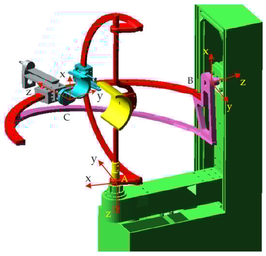
Figure 10.
Positioning of the axes of the kinematic couplings of the ASPIRE robot.
Figure 11a–c shows the time variation graphs for the components of the connecting force in the coupling A in relation to the local reference system attached to this coupling, oriented as in Figure 10. Through this rotation coupling, the module that performs the adduction/abduction movement is connected to the base of the robot with the help of a bearing. By means of an electric motor and a transmission with a worm gearbox, this module is operated and controlled. As previously detailed, the mass of this module is 24.3 kg, to which is added a part of the mass of the lower limb. The analysis of these graphs shows that the maximum value recorded along the X axis of the local reference system in coupling A is −34 N (Figure 11a). The component along the Y axis of the connecting force in coupling A reaches a maximum value of 23 N, and the minimum value is equal to 2.5 N (Figure 11b). Since the weight of 243 N of the adduction/abduction module is oriented along the Z axis, the component along this axis of the connecting force has the highest value, reaching −271 N (Figure 11c). The variation in the negative range of this component is explained by the orientation of the Z axis of the local reference system, which is oriented downwards, and the reaction transmitted to the base is oriented in the opposite direction. The connecting force in coupling A along the Z axis has an additional value of 31 N; this is as compared to the weight of this module of 243 N, which comes from the load given by the support of the patient’s arm and from the interaction with the flexion/extension module. The resulting value of the connecting force in this coupling has a maximum of 274 N and a minimum of 263 N, according to Figure 11d.
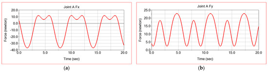
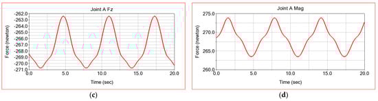
Figure 11.
Connecting forces in the rotation coupling A connected to the base of the adduction/abduction module: (a) in the x direction; (b) in the y direction; (c) in the z direction; and (d) the resultant.
Figure 12 shows the variation laws of the connecting forces in the rotation coupling B, which is defined in ADAMS, between the flexion-extension module and the base. Quite high values are observed of 347 N for the vertical component of the connecting force, which is the one along the X axis of the local reference system from the coupling B (Figure 12a). The reaction along the Y axis has much lower values, reaching a maximum of 57 N (Figure 12b). The connecting force along the Z axis has much lower values, with a maximum of 10 N. This occurs due to the friction interaction between the flexion/extension module and slide 3, as well as due to the opposite resistance of the patient, in this case only by the force of upper limb weight. The fact that the highest value is recorded by the component along the X axis of the connecting force in the coupling B is explicable, because of the weight of the flexion/extension module, equal to 175 N, to which is added both the weight of the upper limb and the interaction between the patient’s upper arm and the robot module (opposite resistance of the upper limb), such that it acts in the opposite direction of the X axis of the local reference system. The fact that the values of the resulting reaction along the X axis are negative is again natural, because the component of the connecting force along the X axis acts downwards and has the opposite direction to the axis of the local reference system attached in the rotation torque B.
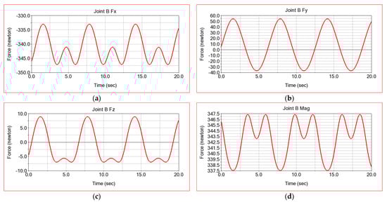
Figure 12.
Connecting forces in the rotating coupling B, connected to the base, of the flexion/extension module: (a) on x direction; (b) on y direction; (c) on z direction; (d) resultant.
In conclusion, according to the results obtained for the connecting forces in couplings A and B, it results that the flexion/extension module is subjected to the highest mechanical stresses. It is therefore necessary to verify its structural integrity with the finite element method, a verification that will be performed later in ANSYS.
4.2. Dynamic Analysis in MSC.ADAMS of the Robot, Considering the Rigid Solid Kinematic Elements and the Friction in the Couplings
The previously presented results for the actuation moments and the connection forces from the kinematic couplings are obtained by numerical simulation in MSC.ADAMS in the simplifying hypothesis, by which the frictions from the kinematic couplings were not taken into account. In reality, the presence of friction in the couplings imprints another character on the dynamics of the ASPIRE robot. For these reasons, in the second phase, we will consider the frictions that appear in the kinematic couplings A, B and C. The parameters necessary for defining the frictions in the kinematic couplings are defined according to the data from Figure 13, for the definition of which the existing data in the literature were taken into account [54]. According to the existing data in the specialized literature, we adopted for the static friction coefficient the value of 0.3, and for the dynamic friction coefficient, we specified the value 0.2.
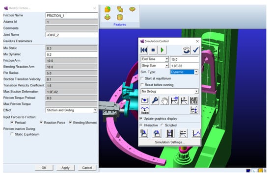
Figure 13.
Parameters defining the friction force in the ASPIRE robot couplings.
The results obtained by numerical simulation in ADAMS, where the friction in the kinematic couplings of the ASPIRE robot is considered, are presented below. The laws of variation of the moment necessary to operate the flexion/extension module, as well as the abduction/adduction module, are presented in Figure 14.
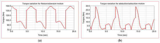
Figure 14.
Second setup ADAMS simulation computed torque for: (a) the flexion-extension module; (b) the adduction-abduction module.
There is an increase in the motor torque required to operate the modules in this case, as well as a steeper variation, similar to that determined experimentally [43].
The results obtained for the connection forces from the kinematic couplings in the hypothesis of considering the friction from the robot joints are presented below. Figure 15 shows the graphs obtained for the variation laws of the connection forces for the coupling A, calculated in the simulation from ADAMS. If we compare these results with those shown in Figure 11, in which case we did not consider the friction in the kinematic couplings, it is found that we have an increase in the connecting forces. Thus, the component along the X axis of the connecting force shows an increase from the value of −36 N to a maximum value of −70 N (Figure 15a). In the case of the connecting force component along the Y axis, the increase occurs from 23 N to 70 N (Figure 15b). There is also an increase in amplitude from 20 N to 100 N. The component of the reaction along the Z axis shows an increase from −271 N to −285 N (Figure 15c). The maximum value of the reaction resulting from the coupling A increases from the value of 274 N to 284 N. It is also found that the presence of friction in the couplings imposes a more dynamic character of the movement, an aspect which is highlighted by the steeper variation of the variation graphs.
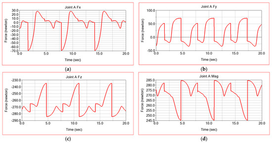
Figure 15.
Connecting forces in the rotation coupling A of the adduction/abduction module, calculated assuming friction: (a) in the x direction; (b) in the y direction; (c) in the z direction; and (d) the resultant.
For coupling B, the connecting forces obtained in Figure 16 are presented in the case of considering the friction in couplings. There is also an increase in the maximum values obtained, assuming the friction of the couplings. Thus, the reaction resulting from coupling B shows an increase from the maximum value of 347 N to the value of 370 N, meaning an increase of 6.62%. The steeper change of the parameter’s variation laws is noticed at the moment of the transition from the flexion movement to the extension for the module that realizes this movement of the arm from adduction to abduction.
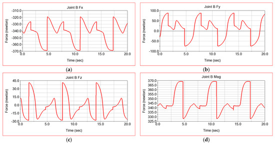
Figure 16.
Connecting forces in coupling B for the rotation of the flexion/extension module calculated assuming friction: (a) in the x direction; (b) in the y direction; (c) in the z direction; and (d) the resultant.
4.3. Dynamic Analysis in MSC.ADAMS of the Robot, Considering the Kinematic Elements as Deformable Solids and Joint Friction
In the third stage of the simulation, the deformability of the kinematic elements of the ASPIRE robot are also considered (flexibility for the two modules of the ASPIRE robot, the flexion/extension and the adduction/abduction modules). The procedure for considering the kinematic elements as deformable solids involves their discretization in finite elements, the calculation of their own modes of vibrations, as well as the calculation of specific deformations and mechanical stresses. The second stage consists of establishing the connection points of the discretized element through kinematic connections with the other elements. Figure 17 shows a construction aspect of a deformable kinematic element in MSC.ADAMS.
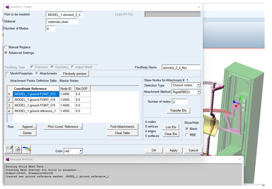
Figure 17.
Defining a deformable element in MSC.ADAMS.
The purpose of this simulation is to obtain results of the dynamic operating parameters of the ASPIRE robot in real operating conditions. Through the dynamic analysis, considering also the flexibility of the kinematic elements, the friction from the kinematic couplings, as well as the external loads, results regarding the real variation of the dynamic parameters have been obtained. Thus, in this stage results will be presented, such as the specific deformation of the robot elements, deformation velocities and accelerations, own frequencies and normal modes of vibration, connection forces in the kinematic couplings and actuation moments.
A first category of results of interest is represented by the moments of actuation of the flexion/extension module, as well as the adduction/abduction module. For this simulation, obviously we used the same loads, given by the weight of the upper limb, as well as the same laws of motion implemented in the motor torques. The dynamic simulation is performed only for a period of 10 s due to the complexity of the model. Thus, for this phase of the dynamic simulation, in Figure 18, the actuation moments corresponding to the flexion/extension and abduction adduction modules are presented. There are very abrupt variations of the dynamic parameters at the beginning of the robot’s movement, which disappear after a second of operation. These aspects are also manifested in the real operation only in the initial phase of the robot’s operation, so it does not affect the proper functioning of the robot and especially the patient.
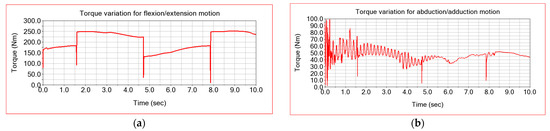
Figure 18.
Third setup ADAMS simulation computed torque for: (a) the flexion-extension module; (b) the adduction-abduction module.
The other parameters of interest for the simulation in the dynamic regime, considering the deformability of the elements, are the translational deformations of some characteristic points of the ASPIRE robot kinematic elements. The variation graphs of the translational deformations for the centre of mass of the flexion/extension module are shown in Figure 18. From these graphs, it is found that the centre of mass of the flexion/extension module registers larger deformations in the first two seconds of operation. As expected, the largest deformation is recorded along the X and Z axes, because the loading produced by the movement of the robot takes place along these axes. The maximum value of the translational deformation of the marker detailed in Figure 19 reaches 0.08 mm.
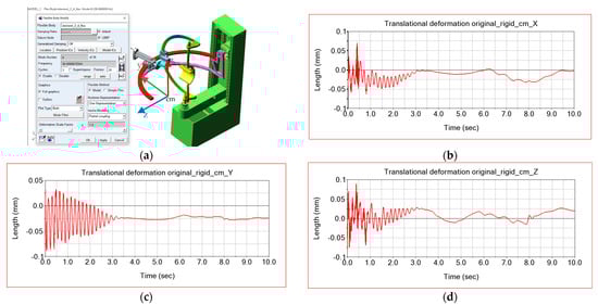
Figure 19.
Translational deformations of the centre of mass of the flexion/extension module in relation to the X, Y and Z axes: (a) marker attached to flexion extension module mass centre; (b) X axis translational deformation; (c) Y axis translational deformation; (d) Z axis translational deformation.
By simulating in dynamic regime and considering the deformability of the kinematic elements of the robot, an overview of the elastic displacements of the elements has been obtained. Thus, Figure 20 presents the distribution maps of the elastic displacements for robot modules. It is observed that the maximum displacement reaches the value of 2.51 mm at the unsupported end of the flexion/extension module.
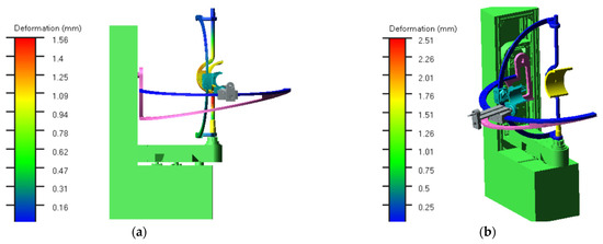
Figure 20.
ASPIRE robot total deformation distribution map in two different moments: (a) at the moment t = 0.001; (b) at the moment t = 0.008 s.
5. Finite Element Analysis in ANSYS of the ASPIRE Robot Flexion/Extension Module
In this section, the results of a finite element analysis in ANSYS for the ASPIRE robot flexion/extension module will be presented. The objectives of this study are as follows:
- Determine the stress concentrators that occur in the structure;
- Optimize the design by eliminating these stress concentrators.
The steps taken to achieve these goals are described below. The verification of interferences and discontinuities was made (lack of contact between elements for the virtual assembly of the flexion-extension module). The existence of interferences prevents the discretization in finite elements for structural analysis. Discontinuities lead to erroneous results because the connecting forces between the components of the subassembly are no longer transmitted. At the same time, the elimination of stress concentrators was made by making a fillet radius in the area of sharp edges or jumps in diameter between circular sections.
The optimized model was transferred to the ANSYS software in order to obtain maps of equivalent stresses based on the finite element method analysis, which represents a modern and very powerful method which is useful for understanding the behavior of the robotic structures, rehabilitation devices and human biomechanics [22,27,55]. It is observed that the analyzed element is composed of six distinct parts which are assembled by threaded joints. The combination of all these pieces to obtain a single element (part) with the help of ANSYS Design Modeler is performed. This aspect is shown in Figure 21. The discretization of the whole set of bodies in finite elements (Figure 21) is achieved using a size of the finite element of 2 mm. Additionally, in the areas where fillet radius appears, a refinement of discretization was performed by using the option “mesh refinement”.
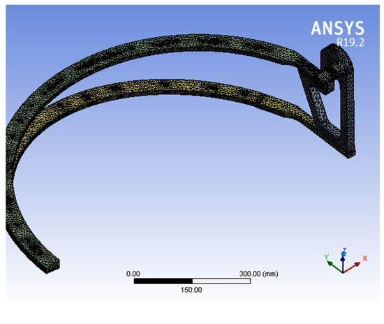
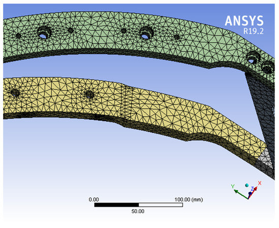
Figure 21.
Discretization in finite elements of the flexion/extension module.
The next step was to fix the cylindrical surface of the coupling B shaft. The load of the element comes from the contact pressure, which has a value of 0.47 MPa. This results from the dynamic model made in MSC.ADAMS, which appears between the guidance surface and the circular portion.
By finite element analysis of the optimized structure (which was obtained by changing the geometry and introducing the fillet radius), equivalent stresses with lower values were obtained compared to those registered at the initial structure, not optimized, when equivalent stresses were 123 MPa. Due to the bending of the circular portions, the contact edge, visible in Figure 22c), produces stress with high values. Filleting these edges reduces the values of these maximum mechanical stresses. The maximum von Mises stress obtained in this case is 64.271 MPa and is recorded at the contact of the joint surfaces.
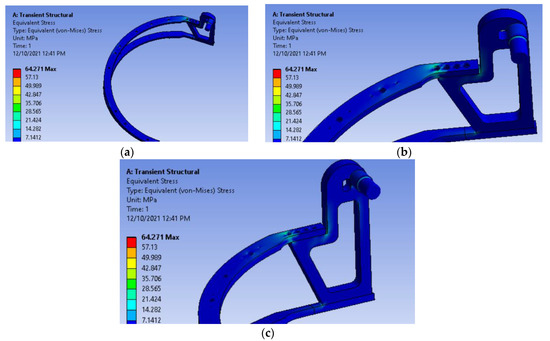
Figure 22.
Distribution of equivalent stresses in the optimized model of the structure: (a) flexion/extension module view; (b) upper corner assembly detail; (c) lower corner detail view.
The maps with the distribution of the displacements recorded along the X and Y axes of the coordinate system are presented in Figure 23. The maximum values recorded are relatively small, at 0.40 mm along the X axis and 0.34 mm along the Y axis, and do not prevent the proper functioning of the module made of aluminum alloy Al 1060. The vertical movement of the module free end reaches 2.6 mm, keeping it within acceptable limits. It is noted that the value of the total elastic displacement obtained in ANSYS is close in value to the result obtained in MSC.ADAMS, presented in Figure 20, where the maximum values are 2.51 mm.
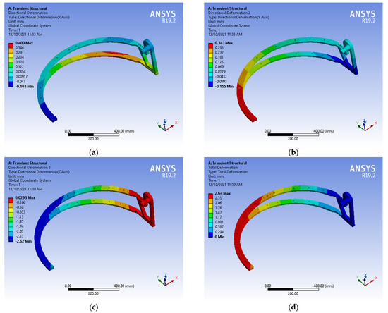
Figure 23.
Distribution of displacements along the axes: (a) X; (b) Y; (c) Z and (d) total displacement.
6. Experimental Determination of the ASPIRE Robot Operating Motor Torques
The results obtained by numerical simulation in ADAMS must also be validated by those obtained experimentally. Thus, in Figure 24, the results obtained experimentally for the actuation moments of the ASPIRE robot modules have been shown [43].
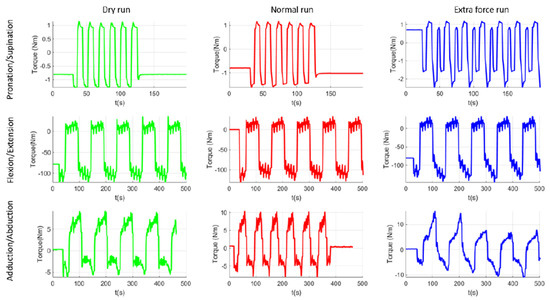
Figure 24.
The torques required to operate the ASPIRE robot, measured experimentally [43].
7. Discussion
A comparison between the experimental results and the results obtained by numerical simulation in MSC.ADAMS, presented in Figure 14, has been made. Therefore, it was observed that the maximum value of the moment necessary to operate the flexion/extension module is 147.37 Nm experimentally, and by numerical simulation in ADAMS we obtained the value of 149 Nm. The negative value recorded in the experimental torque determination comes from the calibration of the torque-recording transducer, with the maximum value being recorded in the negative direction of the axis. MSC.ADAMS shows the absolute, and therefore positive, value of the torque. As a result, in absolute terms, the difference between the maximum experimental value and that obtained by simulation is 1.63 Nm, i.e., less than 1%.
For the moment necessary to operate the adduction/abduction module, we obtained experimentally the maximum moment value of 14.4 Nm, and by numerical simulation in MSC.ADAMS we obtained the value of 25 Nm. It is observed, however, in this case that the allure of the variation curve of the moment obtained by simulation is similar to that obtained experimentally.
A similar approach and the obtained results are presented in previous papers [45] with reference to a dynamic study of a robotic system for lower limb rehabilitation.
In a preliminary study with finite elements of the robot modules, the conclusion is that high stresses appear in the assembly parts of the elements. The optimization of these assemblies was realized by introducing the fillet radius and chamfering the sharp edges. In this way, the maximum stresses decreased from 123 MPa to 64.271 MPa.
Thus, the structural strength of the flexion/extension module was checked in ANSYS FEA software. The kinematic and dynamic parameters of the optimized version of the ASPIRE robot mounted on a virtual mannequin that respects the anthropometric data of a user are studied, considering the component elements as being deformable.
The numerical simulation in MSC.ADAMS should consider the real aspects of the operation, such as friction and deformability of the elements, to obtain results as close as possible to the real situation. To obtain an improved variant of the robot, studies are performed on optimizing the shape and constructive structure of the robot that improves the mechanical strength and dynamic behaviour and leads to the increased stability of the movement of the robot system—the human arm.
The difference between the experimentally recorded maximum values and those obtained by simulation comes from the parameters introduced in the MSC.ADAMS simulation, which may differ from the actual operating conditions. However, the similar allure of variation of the torques obtained experimentally and those obtained by numerical simulation in MSC.ADAMS can be noticed. The results are similar when comparing between the torques measured experimentally and those obtained by numerical simulation in MSC.ADAMS in the case of considering the deformability of the elements.
Additionally, the differences that appear between the experimental results [43] and those obtained by numerical simulation in MSC.ADAMS are explained by the manufacturing tolerances of the parts, as well as the assembly tolerances, which are responsible for the different elasticity of the real robot modules compared to the one considered in the simulation. Moreover, in the simulation, the modules were considered as a unitary assembly, united by fixed couplings. In reality, these elements are joined by removable assemblies, which offer a slightly different elasticity. Nonetheless, there is a clear similarity of the mode of variation for the operating moments of the modules obtained by numerical simulation and experimental determination.
8. Conclusions
The paper presents theoretical research, through virtual and experimental simulation on the dynamics of the ASPIRE robot, used to rehabilitate patients suffering from brachial monoparesis. A model of the ASPIRE robot which includes modules with optimized geometry in terms of how to assemble the components of the modules has been made in SolidWorks.
Another novelty that this study brings is that the numerical simulation in ADAMS, in the situation when the ASPIRE robot is used by a virtual mannequin, elaborated as a 3D Solid Works model based on an average human subject, has been performed. The challenge of the dynamic simulation was to find a way to define the translation couplings between the circular and sliding guides. The option was to define contact as point on the curve. Results for the laws of variation of the actuation moments as well as for the connection forces from the kinematic couplings in three situations have been obtained:
The original elements of this article consist of the dynamic study in MSC.ADAMS of the ASPIRE robot. Results are obtained in three distinct situations:
- (a)
- The kinematic elements were considered as rigid bodies and the friction in the kinematic couplings was not considered;
- (b)
- The kinematic elements were considered as rigid bodies and the friction in the robot couplings was considered;
- (c)
- Both the flexibility of the kinematic elements and the friction in the couplings were considered.
In each of these situations, the results obtained are presented and commented on. Thus, by numerical simulation in MSC.ADAMS, we obtained the connecting forces from the kinematic torques as well as the actuation moments of the robot modules. We obtained these data in the first phase without considering the friction in the couplings; the results are presented in Figure 9, Figure 11 and Figure 12. In the next phase, we also considered the friction from the kinematic torques of the robot, with the results obtained for the actuation moments being presented in Figure 14 and for the connecting forces in Figure 15 and Figure 16. It is noted that if we introduce in the simulation the real operating conditions, the results obtained are much closer to the real ones obtained experimentally.
It is found that the results closest to the experimental ones are those obtained for the most complex situation, namely situation (c). The results obtained by numerical simulation are validated by the experimental results. Moreover, the structural integrity check is performed for the most solicited module, the flexion/extension module. In this way, the stable dynamic behavior of the robot is highlighted, and its safety good functioning is validated for the rehabilitation of the brachial monoparesis.
A methodology for transforming rigid, complex-shaped bodies, such as ASPIRE robot modules, into deformable solids in MSC.ADAMS has been developed. An optimal way to define the contact translational joints in the structure of the ASPIRE robot has been established. In this situation, it is important to correctly define the translational joints, to consider the flexibility of the elements, as well as to define the friction functions, which should consider the stick-slip phenomenon.
The virtual simulation in MSC.ADAMS by comparing the actuation moments determined by simulation with those obtained experimentally has been validated. Thus, the data on the load forces of the elements was used for a structural analysis with finite elements in ANSYS.
Author Contributions
Conceptualization, I.D.G., D.T., G.C. and D.P.; methodology, I.D.G., D.T. and D.P.; software, I.D.G. and D.T.; validation, P.T., D.P. and D.N.T.; formal analysis, I.D.G., P.T. and A.B.; investigation, A.B and M.G.; resources, D.T.; writing—original draft preparation, I.D.G. and A.B.; writing—review and editing, D.T., D.P. and G.C.; visualization, D.N.T. and M.G.; supervision, D.T., D.P. and G.C.; project administration, D.P. All authors have read and agreed to the published version of the manuscript.
Funding
This research was funded by a grant from the Romanian Ministry of Research and Innovation, CCCDI—UEFISCDI, project number PN-III-P2-2.1-PED-2019-3022/546PED/2020 (NeuroAssist) within PNCDI III, and by the project POCU/380/6/13/123927-ANTREDOC, “Entrepreneurial competencies and excellence research in doctoral and postdoctoral studies programs”, co-funded from the European Social Fund through the Human Capital Operational Program 2014–2020.
Institutional Review Board Statement
Not applicable.
Informed Consent Statement
Not applicable.
Data Availability Statement
The data presented in this study are openly available in reference number [30,31,45].
Conflicts of Interest
The authors declare no conflict of interest.
References
- Bureau, U.S.C. The Nation’s Older Population Is Still Growing; Census Bureau: Houtland, MD, USA, 2017. [Google Scholar]
- NSCISC. National Spinal Cord Injury Statistical Center, Facts and Figures at a Glance; NSCISC: Birmingham, UK, 2017. [Google Scholar]
- SPARC. Robots Association. Multi Annual Roadmap for Robotics in Europe; Robots Association: Bruxelles, Belgium, 2017. [Google Scholar]
- Feigin, V.L.; Norrving, B.; Mensah, G.A. Global Burden of Stroke. Circ. Res. 2017, 120, 439–448. [Google Scholar] [CrossRef] [PubMed]
- Lanctôt, K.L.; Lindsay, M.P.; Smith, E.E.; Sahlas, D.J.; Foley, N.; Gubitz, G.; Austin, M.; Ball, K.; Bhogal, S.; Blake, T.; et al. Canadian Stroke Best Practice Recommendations: Mood, Cognition and Fatigue Following Stroke, 6th Edition Update 2019. Int. J. Stroke Off. J. Int. Stroke Soc. 2020, 15, 668–688. [Google Scholar] [CrossRef] [Green Version]
- Skilbeck, C.E.; Wade, D.T.; Hewer, R.L.; Wood, V.A. Recovery after Stroke. J. Neurol. Neurosurg. Psychiatry 1983, 46, 5–8. [Google Scholar] [CrossRef] [Green Version]
- Kwakkel, G.; Kollen, B.J.; van der Grond, J.; Prevo, A.J.H. Probability of Regaining Dexterity in the Flaccid Upper Limb: Impact of Severity of Paresis and Time since Onset in Acute Stroke. Stroke 2003, 34, 2181–2186. [Google Scholar] [CrossRef] [PubMed] [Green Version]
- Iqbal, J.; Bruno, A.; Berger, M. Stroke Causing Pure Brachial Monoparesis. J. Stroke Cerebrovasc. Dis.Off. J. Natl. Stroke Assoc. 1995, 5, 88–90. [Google Scholar] [CrossRef]
- Song, I.-U.; Kim, J.-S.; Kim, Y.-I.; Lee, K.-S. Brachial Monoparesis as an Isolated Manifestation of a Paramedian Pontine Ischemic Lesion. Clin. Neurol. Neurosurg. 2007, 109, 376–378. [Google Scholar] [CrossRef] [PubMed]
- Sivan, M.; Gallagher, J.; Makower, S.; Keeling, D.; Bhakta, B.; O’Connor, R.; Levesley, M. Home-Based Computer Assisted Arm Rehabilitation (HCAAR) Robotic Device for Upper Limb Exercise after Stroke: Results of a Feasibility Study in Home Setting. J. Neuroeng. Rehabil. 2014, 11, 163. [Google Scholar] [CrossRef] [PubMed] [Green Version]
- Bayona, N.A.; Bitensky, J.; Salter, K.; Teasell, R. The Role of Task-Specific Training in Rehabilitation Therapies. Top. Stroke Rehabil. 2005, 12, 58–65. [Google Scholar] [CrossRef] [PubMed]
- Turchetti, G.; Vitiello, N.; Trieste, L.; Romiti, S.; Geisler, E.; Micera, S. Why Effectiveness of Robot-Mediated Neurorehabilitation Does Not Necessarily Influence Its Adoption. IEEE Rev. Biomed. Eng. 2014, 7, 143–153. [Google Scholar] [CrossRef]
- Gorelick, P.B. The Global Burden of Stroke: Persistent and Disabling. Lancet Neurol. 2019, 18, 417–418. [Google Scholar] [CrossRef] [Green Version]
- UK Stroke Association. State of the Nation: Stroke Statistics; UK Stroke Association: London, UK; Available online: https://www.stroke.org.uk/resources/state-nation-stroke-statistics (accessed on 20 August 2021).
- ReNeuron Group plc. CTX Cells for Stroke Disability 15.%09; ReNeuron Group PlC: Bridgend, UK, 2021. [Google Scholar]
- Manna, S.K.; Dubey, V.N. Comparative Study of Actuation Systems for Portable Upper Limb Exoskeletons. Med. Eng. Phys. 2018, 60, 1–13. [Google Scholar] [CrossRef]
- Murie-Fernández, M.; Irimia, P.; Martínez-Vila, E.; John Meyer, M.; Teasell, R. Neuro-rehabilitation after stroke. Neurologia 2010, 25, 189–196. [Google Scholar] [CrossRef]
- Clarke, D.J.; Burton, L.-J.; Tyson, S.F.; Rodgers, H.; Drummond, A.; Palmer, R.; Hoffman, A.; Prescott, M.; Tyrrell, P.; Brkic, L.; et al. Why Do Stroke Survivors Not Receive Recommended Amounts of Active Therapy? Findings from the ReAcT Study, a Mixed-Methods Case-Study Evaluation in Eight Stroke Units. Clin. Rehabil. 2018, 32, 1119–1132. [Google Scholar] [CrossRef] [PubMed] [Green Version]
- Norouzi-Gheidari, N.; Archambault, P.S.; Fung, J. Effects of Robot-Assisted Therapy on Stroke Rehabilitation in Upper Limbs: Systematic Review and Meta-Analysis of the Literature. J. Rehabil. Res. Dev. 2012, 49, 479–496. [Google Scholar] [CrossRef] [PubMed]
- Huang, J.; Tu, X.; He, J. Design and Evaluation of the RUPERT Wearable Upper Extremity Exoskeleton Robot for Clinical and In-Home Therapies. IEEE Trans. Syst. Man Cybern. Syst. 2015, 46, 1–10. [Google Scholar] [CrossRef]
- Al-Fahaam, H.; Davis, S.; Nefti-Meziani, S. Wrist Rehabilitation Exoskeleton Robot Based on Pneumatic Soft Actuators. In Proceedings of the 2016 International Conference for Students on Applied Engineering (ICSAE), Newcastle upon Tyne, UK, 20–21 October 2016; pp. 491–496. [Google Scholar] [CrossRef]
- Tarnita, D.; Pisla, D.; Geonea, I.; Vaida, C.; Catana, M.; Tarnita, D.N. Static and Dynamic Analysis of Osteoarthritic and Orthotic Human Knee. J. Bionic Eng. 2019, 16, 514–525. [Google Scholar] [CrossRef]
- Vaida, C.; Plitea, N.; Carbone, G.; Birlescu, I.; Ulinici, I.; Pisla, A.; Pisla, D. Innovative Development of a Spherical Parallel Robot for Upper Limb Rehabilitation. Int. J. Mech. Robot. Syst. 2018, 4, 256. [Google Scholar] [CrossRef]
- Carbone, G.; Gherman, B.; Ulinici, I.; Vaida, C.; Pisla, D. Design Issues for an Inherently Safe Robotic Rehabilitation Device. In Advances in Service and Industrial Robotics, Proceedings of the International Conference on Robotics in Alpe-Adria Danube Region, Patras, Greece, 6–8 June 2018; Springer: Cham, Switzerland, 2017; pp. 1025–1032. [Google Scholar] [CrossRef]
- Görgülü, İ.; Carbone, G.; Dede, M. Time Efficient Stiffness Model Computation for a Parallel Haptic Mechanism via the Virtual Joint Method. Mech. Mach. Theory 2020, 143, 103614. [Google Scholar] [CrossRef]
- Vaida, C.; Birlescu, I.; Pisla, A.; Ulinici, I.; Tarnita, D.; Carbone, G.; Pisla, D. Systematic Design of a Parallel Robotic System for Lower Limb Rehabilitation. IEEE Access 2020, 8, 34522–34537. [Google Scholar] [CrossRef]
- Tarnita, D.; Marius, M.C.; Tarnita, D. Contributions on the Modeling and Simulation of the Human Knee Joint with Applications to the Robotic Structures. In Mechanisms and Machine Science; Springer: Cham, Switzerland, 2014; Volume 20, pp. 283–297. [Google Scholar] [CrossRef]
- Gherman, B.; Birlescu, I.; Plitea, N.; Carbone, G.; Tarni, D.; Pisla, D.; Tarniţă, D.; Tarni, D.; Pisla, D. On The Singularity-Free Workspace of a Parallel Robot For Lower-Limb Rehabilitation. In Proceedings of the Romanian Academy, Series A; The Publishing House of the Romanian Academy: Bucharest, Romania, 2020; pp. 383–391. [Google Scholar]
- Tarnita, D.; Marghitu, D.B. Analysis of a Hand Arm System. Robot. Comput. Manuf. 2013, 29, 493–501. [Google Scholar] [CrossRef]
- Tucan, P.; Vaida, C.; Plitea, N.; Pisla, A.; Carbone, G.; Pisla, D. Risk-Based Assessment Engineering of a Parallel Robot Used in Post-Stroke Upper Limb Rehabilitation. Sustainability 2019, 11, 2893. [Google Scholar] [CrossRef] [Green Version]
- Tucan, P.; Vaida, C.; Ulinici, I.; Banica, A.; Burz, A.; Pop, N.; Birlescu, I.; Gherman, B.; Plitea, N.; Antal, T.; et al. Optimization of the ASPIRE Spherical Parallel Rehabilitation Robot Based on Its Clinical Evaluation. Int. J. Environ. Res. Public Health 2021, 18, 3281. [Google Scholar] [CrossRef] [PubMed]
- Gull, M.A.; Bai, S.; Bak, T. A Review on Design of Upper Limb Exoskeletons. Robotics 2020, 9, 16. [Google Scholar] [CrossRef] [Green Version]
- Valevicius, A.M.; Jun, P.Y.; Hebert, J.S.; Vette, A.H. Use of Optical Motion Capture for the Analysis of Normative Upper Body Kinematics during Functional Upper Limb Tasks: A Systematic Review. Off. J. Electromyogr. Kinesiol. J. Int. Soc. Electrophysiol. Kinesiol. 2018, 40, 1–15. [Google Scholar] [CrossRef]
- Li, J.; Cao, Q.; Dong, M.; Zhang, C. Compatibility Evaluation of a 4-DOF Ergonomic Exoskeleton for Upper Limb Rehabilitation. Mech. Mach. Theory 2021, 156, 104146. [Google Scholar] [CrossRef]
- Culmer, P.R.; Jackson, A.E.; Makower, S.G.; Cozens, J.A.; Levesley, M.C.; Mon-Williams, M.; Bhakta, B. A Novel Robotic System for Quantifying Arm Kinematics and Kinetics: Description and Evaluation in Therapist-Assisted Passive Arm Movements Post-Stroke. J. Neurosci. Methods 2011, 197, 259–269. [Google Scholar] [CrossRef] [PubMed]
- Shahar, N.; Schwartz, I.; Portnoy, S. Differences in Muscle Activity and Fatigue of the Upper Limb between Task-Specific Training and Robot Assisted Training among Individuals Post Stroke. J. Biomech. 2019, 89, 28–33. [Google Scholar] [CrossRef]
- Byl, N.N.; Abrams, G.M.; Pitsch, E.; Fedulow, I.; Kim, H.; Simkins, M.; Nagarajan, S.; Rosen, J. Chronic Stroke Survivors Achieve Comparable Outcomes Following Virtual Task Specific Repetitive Training Guided by a Wearable Robotic Orthosis (UL-EXO7) and Actual Task Specific Repetitive Training Guided by a Physical Therapist. J. Hand Ther. 2013, 26, 343–352. [Google Scholar] [CrossRef] [PubMed]
- Sanjuan, J.; Castillo, A.D.; Padilla Ramirez, M.; Quintero, M.C.; Gutierrez, E.E.; Sampayo, I.; Hernandez, J.R.; Rahman, M. Cable Driven Exoskeleton for Upper-Limb Rehabilitation: A Design Review. Rob. Auton. Syst. 2020, 126, 103445. [Google Scholar] [CrossRef]
- Ben Hamida, I.; Laribi, M.A.; Mlika, A.; Romdhane, L.; Zeghloul, S.; Carbone, G. Multi-Objective Optimal Design of a Cable Driven Parallel Robot for Rehabilitation Tasks. Mech. Mach. Theory 2021, 156, 104141. [Google Scholar] [CrossRef]
- Nelson, C.; Nouaille, L.; Poisson, G. A Redundant Rehabilitation Robot with a Variable Stiffness Mechanism. Mech. Mach. Theory 2020, 150, 103862. [Google Scholar] [CrossRef]
- Major, Z.Z.; Vaida, C.; Major, K.A.; Tucan, P.; Simori, G.; Banica, A.; Brusturean, E.; Burz, A.; Craciunas, R.; Ulinici, I.; et al. The Impact of Robotic Rehabilitation on the Motor System in Neurological Diseases. A Multimodal Neurophysiological Approach. Int. J. Environ. Res. Public Health 2020, 17, 6557. [Google Scholar] [CrossRef] [PubMed]
- Vaida, C.; Plitea, N.; Pisla, D.; Carbone, G.; Gherman, B.; Ulinici, I. Spherical Robot for Medical Recovery of Upper Limb Proximal Area. Patent NO. RO132233 3, 30 March 2020. [Google Scholar]
- Pisla, D.; Tarnita, D.; Tucan, P.; Tohanean, N.; Vaida, C.; Geonea, I.D.; Bogdan, G.; Abrudan, C.; Carbone, G.; Plitea, N.C. A Parallel Robot with Torque Monitoring for Brachial Monoparesis Rehabilitation Tasks. Appl. Sci. 2021, 11, 9932. [Google Scholar] [CrossRef]
- Available online: https://www.mscsoftware.com/product/adams (accessed on 25 May 2021).
- Geonea, I.; Tarnita, D. Design and Evaluation of a New Exoskeleton for Gait Rehabilitation. Mech. Sci. 2017, 8, 307–321. [Google Scholar] [CrossRef]
- Tarnita, D.; Geonea, I.; Petcu, A. Experimental Human Walking and Virtual Simulation of Rehabilitation on Plane and Inclined Treadmill. In Acoustics and Vibration of Mechanical Structures—AVMS-2017; Springer Proceedings in Physics; Springer: Cham, Switzerland, 2018; pp. 149–155. [Google Scholar] [CrossRef]
- Nair, A.; Deenadayalan, E. Performance Analysis of Super Twisting Sliding Mode Controller by ADAMS–MATLAB Co-Simulation in Lower Extremity Exoskeleton. Int. J. Precis. Eng. Manuf. Technol. 2020, 7, 743–754. [Google Scholar] [CrossRef]
- Soliman, A.F.; Sendur, P.; Ugurlu, B. 3-D Dynamic Walking Trajectory Generation for a Bipedal Exoskeleton with Underactuated Legs: A Proof of Concept. In Proceedings of the 2019 IEEE 16th International Conference on Rehabilitation Robotics (ICORR), Toronto, ON, Canada, 24–28 June 2019; pp. 599–604. [Google Scholar] [CrossRef]
- Lee, Y.; Kim, Y.-J.; Lee, J.; Lee, M.; Choi, B.; Kim, J.; Park, Y.J.; Choi, J. Biomechanical Design of a Novel Flexible Exoskeleton for Lower Extremities. IEEE/ASME Trans. Mechatron. 2017, 22, 2058–2069. [Google Scholar] [CrossRef]
- Berceanu, C.; Tarnita, D.; Filip, D. About an experimental approach used to determine the kinematics of a human. Solid State Phenom. 2010, 166–167, 45–50. [Google Scholar] [CrossRef]
- Menga, G.; Ghirardi, M. Lower Limb Exoskeleton for Rehabilitation with Improved Postural Equilibrium. Robotics 2018, 7, 28. [Google Scholar] [CrossRef] [Green Version]
- Lin, P.-Y.; Shieh, W.-B.; Chen, D.-Z. A Theoretical Study of Weight-Balanced Mechanisms for Design of Spring Assistive Mobile Arm Support (MAS). Mech. Mach. Theory 2013, 61, 156–167. [Google Scholar] [CrossRef]
- Craig, R.R.; Bampton, M.C.C. Coupling of substructures for dynamics analyses. AIAA J. 1968, 6, 1313–1319. [Google Scholar] [CrossRef] [Green Version]
- Pennestri, E.; Rossi, V.; Salvini, P.; Valentini, P.P. Review and Comparison of Dry Friction Force Models. Nonlinear Dyn. 2016, 83, 1785–1801. [Google Scholar] [CrossRef]
- Tarnita, D.; Marius, M.; Dumitru, N.; Tarnita, D.N. Design and Simulation of an Orthotic Device for Patients with Osteoarthritis. In New Trends in Medical and Service Robots; Mechanisms and Machine Science; Springer: Cham, Switzerland, 2016; Volume 38, pp. 61–77. [Google Scholar] [CrossRef]
Publisher’s Note: MDPI stays neutral with regard to jurisdictional claims in published maps and institutional affiliations. |
© 2021 by the authors. Licensee MDPI, Basel, Switzerland. This article is an open access article distributed under the terms and conditions of the Creative Commons Attribution (CC BY) license (https://creativecommons.org/licenses/by/4.0/).