Featured Application
The results of this research proved the adequate performance of the sand-tire shred mixtures in reducing peak blast pressure, which is the leading cause of damage to underground structures under surface explosion.
Abstract
Blasting is an unavoidable activity in geotechnical engineering, road and tunnel construction, and mining and quarrying. However, this activity can expose the environment to various hazards that are challenging to control and, at the same time, critical for the safety of site workers, equipment, and surrounding structures. This research aims to evaluate the ability of sand–tire shred mixtures to reduce peak blast pressure, which is the leading cause of damage to underground structures under surface explosion. ABAQUS software is used to model the material behavior under explosion and is validated using the results of previous studies and an empirical equation. Different scenarios are created by using mixture layers with different thicknesses (2, 4, and 6 m) and tire shred contents (10%, 20%, and 30%) that are subjected to various surface explosion charges (100, 500, 1000, and 5000 kg). The thickness of the mixture layer is found to be directly related to the dissipation of explosion energy. However, the percentage of the rubber content in the mixture is only significant in reducing peak blast pressure when a thick enough mixture layer is used. The results confirm the adequate performance of the correctly chosen sand–tire shred mixtures in reducing peak blast pressure and protecting the underground structure from surface explosion hazards.
1. Introduction
A surface explosion can cause damage to underground structures; therefore, soil behavior must be evaluated under explosion hazards so that we may be able to create a blast-resistant design for these structures [1,2,3]. Blast-induced vibration parameters have received attention from many researchers [4,5,6]; amongst the findings is that peak blast pressure is the most critical parameter for underground structures [7,8,9]. This parameter is directly related to peak particle velocity, with different empirical equations defining them [10,11,12]. Several studies have explicitly focused on peak blast pressure in sand. Peak pressure and particle velocity in sand decrease with their increasing distance from the center of the explosion, whereas these parameters increase with an increase in explosion charge weight [6,13,14]. The soil type also significantly affects peak pressure; the denser the soil, the higher the peak pressure [15]. Although many studies have been conducted to evaluate the behavior of different soils under explosion conditions, the performance of sand–tire shred mixture has not been studied to see whether it has any effects on surface explosion energy dissipation.
Millions of scrap tires are stored in the ecosystem annually, causing environmental issues [16]. Some countries have recently invested in recycling and reusing waste tires, but still, in other countries, it is only a small percentage of waste tires that are recycled or reused, and the rest are destined for landfills, stockpiles, or illegal disposals [17,18,19,20]. With an increasing volume of waste produced each year, this low level of recycling will not be enough to eliminate the environmental issues associated with the waste tires. On the positive side, the recycling rate of waste tires has increased in the last decades, and a significant number of researchers have paid attention to recycling and reusing waste tires in different industries [21,22]. Due to their low density, high drainage, and high energy dissipation capacity [23,24], waste tires can be used in various engineering applications to improve or alter the mechanical properties of soils [25,26]. A typical application is to combine the tire shreds with sandy soils. This mixture has been used in different projects such as backfilling, embankment constructions, soil reinforcement, road construction, liquefaction mitigation, and seismic base isolation [16,27,28,29,30,31,32,33,34,35].
The ability of sand–tire shred mixtures to dissipate vibration energy has been demonstrated in seismic base isolators. Pamukcu and Akbulut [36] reported an increase in the damping ratio of sand due to the addition of tire shreds. Wang et al. [37] showed that the damping ratio of sand–tire shred mixtures significantly increases with increasing the rubber content. Senetakis et al. [38] reported that the maximum damping ratio of pure sand is less than 10%, whereas the corresponding value is up to 15% for sand–tire shred mixtures. Because of its high energy dissipation capacity, this mixture has been used in other engineering applications such as railway sub-ballast layers [39,40] and geotechnical seismic isolation [41,42,43]. Xiong and Li [44] showed that geotechnical seismic isolation could effectively mitigate seismic hazards. Dhanya et al. [45] showed that a 50% reduction in the seismic shear force of low-rise buildings could be achieved using geotechnical seismic isolation. Due to the superior performance of this mixture in dissipating vibration energy, it is worthy of investigation for controlling surface explosion hazards.
Several researchers have paid attention to determining the engineering properties of sand–tire shred mixtures. Foose et al. [46] performed a series of direct shear tests on this mixture and showed that the most critical factors affecting shear strength were the rubber content and the mixture density. Anbazhagan et al. [47] showed that the size of granulated rubber significantly affects the mixtures’ properties. Mohamad et al. [48] concluded that the shear strength of the sand–tire shred mixture increases with increasing rubber content up to 10%. Some studies, however, reported a reduction of shear strength with an increase in rubber content [49,50]. The effect of rubber content on the friction angle has also been investigated. Livingston and Ravichandran [51] reported that the friction angle of the mixture increases with an increase in rubber content. In contrast, Lee et al. [46] found that the friction angle of the mixture decreases with an increase in rubber content. Therefore, it is difficult to come to a conclusion about the effect of tire shred on soil properties without proper analysis.
Taking into consideration the need to recycle and reuse waste tires and prompted by research on the proven effectiveness of sand–tire shred mixtures in dissipating vibration energy, this research investigates further the effect of these mixtures to control surface explosion hazards affecting underground structures.
2. Materials and Methods
2.1. Blast Loading
The blast wave is propagated through the explosion source due to a sudden release of energy during a short time. This wave applies an incident pressure on each of the surfaces surrounding the explosion [52,53,54]. A typical incident pressure–time history is divided into positive and negative phases as described in Bulson’s illustration of time history of incident pressure and expressed using Equation (1) [54].
where P(t) is the incident pressure; P0 is the ambient air pressure; Pso is the peak incident pressure; td is the positive phase duration; and the coefficient b represents the extension of the negative phase. Various empirical equations have been proposed for peak incident pressure [55,56,57]. These empirical equations predict peak incident pressure as a function of a scaled distance parameter. This scaled distance is defined by Equation (2) [54].
where R is the standoff distance from the explosion source in m, and W is the equivalent charge of TNT in kg. Naumyenko and Petrovsky [58] proposed Equations (3) and (4) as the earliest empirical equations for peak incident pressure [58].
The pressure induced by blast wave propagation in a soil medium is different from the incident pressure. Many studies have investigated the blast-induced vibration parameters for a soil medium [4,5,6]. The peak pressure in different soil types can be obtained by Equations (5) and (6) [15].
where po is the peak pressure in N/m2; ρ is the density of soil in kg/m3; u is the peak particle velocity in m/s; fc is a dimensionless coupling factor that depends on the scaled depth of explosion; R is the distance of the measuring point from the center of charge in m; n is a dimensionless attenuation coefficient; and C is the loading wave velocity in m/s, which is determined by Equation (7) [13].
where c is the seismic velocity in m/s. The coupling factor is determined as 0.4 for surface explosions and increases with the depth of the explosion according to the scaled depth of the explosion, based on TM 5-855-1 [15]. The attenuation coefficient depends on the soil type, as presented in Table 1.

Table 1.
Attenuation coefficient for different soil types [13].
Another parameter that has received attention by many researchers in the last decades is the blast-induced crater [14,59,60]. The effect of sand–tire shred mixtures on the blast-induced crater is also evaluated in this research. The analysis of the explosion scenarios has been performed based on the coupled Eulerian–Lagrangian analysis where the Jones-Wilkins-Lee (JWL) equation of state [61] is used to simulate the explosion materials as shown in Equation (8).
where pb is the blast pressure; υ = 1/ρb is the specific volume; e is the specific internal energy; C1, r1, C2, r2, and ω are the experimentally determined constants determined by different researchers [62,63,64].
2.2. Sand–Tire Shred Mixture
An approach to reduce the environmental effects of waste tires is to recycle and reuse them in different industries. Shred tires are typically used in geotechnical and civil engineering in combination with different soil types to alter their engineering properties. This research evaluates the behavior of a sand-tire shred mixture against surface explosion hazards. The engineering properties of the soil and mixture used in this research are based on the results of the studies conducted by Anvari et al. [65] and Ambrosini and Luccioni [66] on sand and various shred tire (rubber) contents (0%, 5%, 10%, 20%, and 30%), as shown in Table 2, where ρ is the soil density; G is the shear modulus; μ is the Poisson ratio; φ is the internal friction angle; Cs is the soil cohesion; and α and β are Rayleigh damping coefficients related to the mass and stiffness matrices, respectively. The Rayleigh damping coefficients used in this research are based on Dhanya et al. [67].

Table 2.
Engineering properties of the soil and mixture [65,66].
2.3. Numerical Analysis
A numerical analysis is used in this research to evaluate the behavior of sand–tire shred mixtures under surface explosion hazards and investigate whether this mixture can be introduced as an effective method to protect underground structures from peak blast pressure. Figure 1 shows the explosion scenarios investigated in this research. A sand layer is initially subjected to four surface explosions with 100, 500, 1000, and 5000 kg charges. The sand–tire shred mixture is then introduced to the model with 2, 4, and 6 m thicknesses and subjected to the same surface explosions.
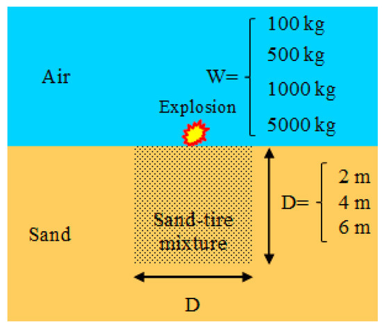
Figure 1.
The schematic model used for developing explosion scenarios.
The air is modeled using the ideal gas equation of state, where the internal energy depends on the temperature. The ideal gas equation is shown in Equations (9) and (10) [59].
where pa is the hydrostatic pressure of the air; γ is the adiabatic exponent; ρa is the air density; e is the specific internal energy depending on temperature T0; Ra is the universal gas constant divided by the effective molecular weight of the gas; and cv is the specific heat at constant volume. Table 3 presents the material properties for the air [59].

Table 3.
Material properties for the air [59].
The JWL equation of state [61] is used to model the explosion with the parameters stated in Table 4 [59]. The stress–strain response of sand–tire shred mixtures is simulated using the Mohr-Coulomb constitutive model.

Table 4.
Material properties for the explosion [59].
The numerical analysis consists of several steps, including validation of the numerical simulation, studying the behavior of the sand–tire shred mixture under different explosion scenarios, investigating the effect of the thickness of the sand–tire shred mixture on peak blast pressure, and evaluating the impact of the rubber content on peak blast pressure, as discussed in the following sections.
The ABAQUS software is used for the finite element simulation in this research, and the initial results are validated against the results reported by Ambrosini and Luccioni [66] and the equation of peak blast pressure [15]. The finite element model is developed and analyzed using the ABAQUS Explicit module. This module is suitable for dynamic events such as explosions and efficiently solves highly nonlinear problems involving changing contact conditions. The coupled Eulerian–Lagrangian method is used to model the explosion, air, and sand–tire shred mixture as an Eulerian element. This method is suitable for analyzing problems with large deformations. As described in previous sections, the explosion material is simulated using the JWL equation of state.
The blast scenario is a surface explosion with a charge of 500 kg. Figure 2 shows the results of numerical model simulation in ABAQUS software. The surface explosion produced a crater with a diameter of 4.24 m (Figure 2b) compared with a crater diameter of 4.22 m reported by Ambrosini and Luccioni [66], which indicated an insignificant difference of 0.5%. Figure 2c shows the time history of blast pressure at a depth of 10 m obtained by this research, which offers a peak blast pressure of 0.4 MPa, with a slight difference of 4.7% compared with the corresponding value obtained from Equation (5), equal to 0.42 MPa. These results indicate that the developed numerical model in this research can accurately simulate soil behavior under surface explosion.
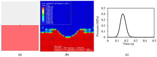
Figure 2.
Results of numerical model simulation in ABAQUS software: (a) model before the explosion; and (b) blast-induced crater after the explosion; and (c) time history of blast pressure at a depth of 10 m.
3. Results and Discussions
3.1. Effect of Sand–Tire Shred Mixture on Peak Blast Pressure
A 6-m-thick layer of the mixture of 30% shred tire (rubber) and 70% sand is modeled and investigated to determine the effect of the mixture layer on the blast-induced vibration parameters compared with the response of pure sand. Table 5 includes the dimensions of the blast-induced crater under different explosion charge weights. The sand–tire shred mixtures effectively reduce the diameter of the blast-induced crater in all scenarios. The crater’s depth is also decreased by the presence of the mixture layer, except under the 5000 kg explosion charge. The reduced weight of the mixture compared with the sand is believed to be the leading cause of this anomaly. The high-energy explosion, in direct contact with the lightweight mixture layer, forms a deep crater before this layer can dissipate the blast energy.

Table 5.
Dimensions of the blast-induced crater.
Figure 3 presents the simulation results in terms of peak blast pressure at different depths under charge weight explosion scenarios. The results indicate that the sand–tire shred mixture contributes to a significant reduction of peak blast pressure. It is worth noting that peak blast pressure data are only available at depths below the base of the craters (see Table 5). The most significant reduction is 90%, which was achieved at a depth of 2 m under a 100 kg charge, followed by an 84% reduction at a depth of 3 m under a 1000 kg charge, an 83% reduction at a depth of 3 m under a 500 kg charge, and a reduction of 23.6% at a depth of 11 m under a 5000 kg charge. The peak blast pressure reduction at the base of the mixture layers—6 m below the surface—under the surface explosion charges of 100, 500, and 1000 kg was 63%, 63%, and 61%, respectively. Due to the extension of the crater to a depth of 7.8 m below a 5000 kg charge, the first peak blast pressure data for this mixture layer were available at a depth of 8 m below the surface, showing a reduction of 23% compared with pure sand.
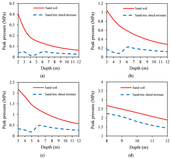
Figure 3.
Effect of sand–tire shred mixture on peak blast pressure under surface explosion with charge weights of (a) 100 kg; (b) 500 kg; (c) 1000 kg; and (d) 5000 kg.
These results indicate that peak blast pressure decreased with depth for pure sand and the mixture layer. Although the effect of the mixture layer in reducing the peak blast pressure lessens by depth, it is still notably more significant than pure sand at the maximum depth of analysis (12 m under the surface). The peak blast pressure reductions recorded at this depth for the mixture layer compared with pure sand were 58%, 58%, 54%, and 24% under surface charges of 100, 500, 1000, and 5000 kg, respectively. A noteworthy point in the results is a sudden increase in peak blast pressure at the base of the mixture layers, as shown in Figure 3a–c. Equation (5) states that soil density directly impacts the peak pressure; therefore, this increase at the interface of two layers is due to the higher density of sand in the mixture layer.
3.2. Effect of Thickness of Sand–Tire Shred Mixture on Peak Blast Pressure
Two additional sand–tire shred mixture layers with thicknesses of 2 and 4 m and the same mixture of 30% shred tire (rubber) and 70% sand are added to the investigation to evaluate the effect of layer thickness on peak blast pressure under different explosion scenarios. Figure 4 shows the results of the simulations for the three mixture layers with varying thicknesses under four surface explosion charges. The results show that the thickness of the sand–tire shred mixture has a significant effect on its behavior under an explosion hazard, especially at lower depths. The overall behavior of the mixture layers indicates the positive impact of thicker layers in reducing peak pressure. This impact is more noticeable up to the interface of the mixture layers with sand. An increase in the value of peak blast pressure is seen at the interface of the layers, followed by a gradual decrease at a greater depth.
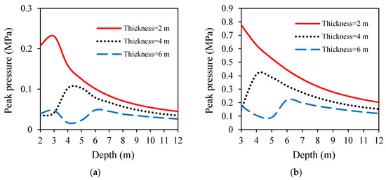
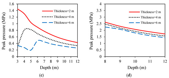
Figure 4.
Effect of thickness of sand–tire shred mixture on peak blast pressure under surface explosion with charge weights of (a) 100 kg; (b) 500 kg; (c) 1000 kg; and (d) 5000 kg.
A similar trend is observed for the simulations under 100, 500, and 1000 kg charges in terms of peak pressure reduction. The most significant peak pressure decrease under a 100 kg charge (Figure 4a) is 81%, which occurs at 2 m depth by increasing the thickness of the sand–shred tire layer from 2 m to either 4 or 6 m. The most significant reduction in peak blast pressure (between 79% to 81%) under 500 kg (Figure 4b) and 1000 kg (Figure 4c) charges occur at a depth of 3 m by increasing the thickness of the mixture layer from 2 m to either 4 or 6 m. The explosion of a 5000 kg charge (Figure 4d) extended the crater to a depth of 8 m, where the thickness of the mixture layer played a less significant role in reducing peak blast pressure. The results show that the mixture layer’s thickness is a critical parameter in reducing the peak pressure under all explosion scenarios. The thicker the mixture layer, the more significantly it reduces peak blast pressure. This is more evident near the surface and less prominent in the depths below the interfaces of the mixture layer and sand.
3.3. Effect of Rubber Content on Peak Blast Pressure
The effect of different rubber contents on the peak blast pressure is evaluated in this section, following the mixture patterns stated in Table 2 [65]. Two new mixture layers, formed by 10% and 20% rubber contents added to 90% and 80% sand, respectively, are included in the analysis. Based on similar behavioral trends found in previous sections, the effect of rubber content is investigated only for the mixture layers with 2 and 6 m thicknesses under 500, 1000, and 5000 kg charges. Figure 5a,c,e shows that the rubber content does not significantly affect the peak blast pressure for the 2-m-thick mixture layer. However, it has a more evident impact on the 6-m-thick mixture layer, especially at lower depths, as seen in Figure 5b,d,f. For a 6-m-thick mixture layer subjected to a 500 kg charge (Figure 5b), the peak blast pressure decreases by 42% and 59% by increasing the rubber content from 10% to 20% and 30%, respectively. In a similar trend, the peak pressure for the same mixture layer under a 1000 kg charge (Figure 5d) shows a reduction of 41% and 58% by increasing the rubber content from 10% to 20% and 30%, respectively. The formation of a deep crater under a 5000 kg charge (Figure 5f) resulted in the least noticeable effect on peak pressure by increasing the rubber content. From the comparison between all the scenarios, it can be concluded that increasing the rubber content has a more significant effect on peak pressure reduction in lower depths and under lower power explosions.
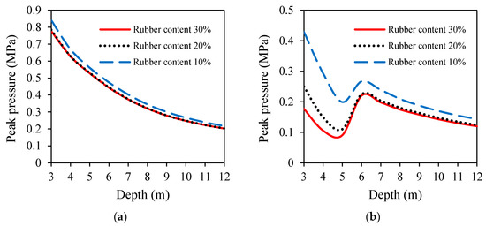
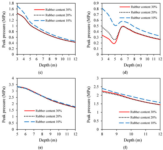
Figure 5.
Effect of rubber content on peak blast pressure for 2- and 6-m-thick mixture layers under surface explosion with charge weights of 500, 1000, and 5000 kg: (a) 2-m-thick mixture layer and 500 kg charge. (b) 6-m-thick mixture layer and 500 kg charge; (c) 2-m-thick mixture layer and 1000 kg charge; (d) 6-m-thick mixture layer and 1000 kg charge; (e) 2-m-thick mixture layer and 5000 kg charge; (f) 6-m-thick mixture layer and 5000 kg charge.
4. Conclusions
This research investigates the behavior of sand–tire shred mixtures under various surface explosion hazards and scenarios, which is a unique application. The aim was to evaluate the ability of this mixture to dissipate the energy of surface explosions and reduce peak blast pressure as the leading destructive impact energy for underground services and structures. To this end, mixtures of fine-grained sand and shred tire were subjected to surface explosions with varying charges. Sand–tire shred mixture layers with thicknesses of 2, 4, and 6 m and rubber contents of 10%, 20%, and 30% were investigated under 100, 500, 1000, and 5000 kg surface explosion scenarios. The results proved the success of a 6-m-thick sand–tire shred mixture in reducing peak blast pressure in all simulations when compared with pure sand. The most significant reduction was 90%, which was achieved at a depth of 2 m under a 100 kg charge, followed by an 84% reduction at a depth of 3 m under a 1000 kg charge, an 83% reduction at a depth of 3 m under a 500 kg charge, and an average reduction of above 20% at depths between 8 to 12 m under a 5000 kg charge.
Further investigation showed that the thickness of the mixtures layers has a significant effect on their behavior under explosion hazards, especially at lower depths. The peak blast pressure under a 100 kg charge was reduced by up to 81% when the thickness of the mixture layer increased from 2 m to either 4 or 6 m. This reduction was between 79% to 81% under 500 and 1000 kg charges at a depth of 3 m. However, the thickness of the mixture layers had a less significant impact on reducing peak pressure at greater depth than the mixture and sand layer interface. This finding would suggest that the optimum thickness of the mixture layer should be determined by considering the distance of the underground structure from the surface explosion charge and calculating the required amount of energy dissipation to avoid explosion hazards.
An investigation on the mixture layer’s tire shred (rubber) content indicated that it does not significantly affect peak blast pressure for any explosion scenarios with the 2-m-thick mixture layer. However, increasing the rubber content from 10% to 20% and 30% for the 6-m-thick mixture layer resulted in a more significant reduction in peak blast pressure under 200 and 1000 kg charges. The formation of a deep crater under a 5000 kg charge resulted in the least noticeable effect on peak pressure by increasing the rubber content. Overall results indicated that increasing the rubber content significantly affects peak pressure reduction in lower depths and under lower power explosions.
This research has proven the adequate performance of the sand–tire shred mixtures in reducing peak blast pressure, which is the leading cause of damage to underground structures under surface explosion. The thickness and rubber content of the mixture layer need to be carefully designed based on each explosion scenario by considering the distance of the explosion charge from the structure, the weight of the explosion charge, and the safe peak blast pressure to protect the structure from surface explosion hazards. It is recommended that further research in this area integrate soil–structure interaction in the analysis based on specific characteristics of different underground structures.
Author Contributions
Conceptualization, M.H. and M.K.; methodology, M.K. and P.G.A.; software, P.G.A.; validation, H.D.; formal analysis, H.D. and R.K.; investigation, R.K.; writing—original draft preparation, H.D. and M.H.; writing—review and editing, R.K.; supervision, P.G.A. All authors have read and agreed to the published version of the manuscript.
Funding
This research received no external funding.
Conflicts of Interest
The authors declare no conflict of interest.
References
- Mandal, J.; Goel, M.D.; Agarwal, A.K. Underground Structures Subjected to Various Blast Loading Scenarios: A Scoping Review. Arch. Comput. Methods Eng. 2021. [Google Scholar] [CrossRef]
- Mussa, M.H.; Mutalib, A.A.; Hamid, R.; Naidu, S.R.; Radzi, N.A.M.; Abedini, M. Assessment of damage to an underground box tunnel by a surface explosion. Tunn. Undergr. Space Technol. 2017, 66, 64–76. [Google Scholar] [CrossRef]
- Qian, H.; Zong, Z.; Wu, C.; Li, J.; Gan, L. Numerical study on the behavior of utility tunnel subjected to ground surface explosion. Thin Walled Struct. 2021, 161, 107422. [Google Scholar] [CrossRef]
- Yankelevsky, D.; Karinski, Y.; Feldgun, V. Re-examination of the shock wave’s peak pressure attenuation in soils. Int. J. Impact Eng. 2011, 38, 864–881. [Google Scholar] [CrossRef]
- Hosseini, S.A.; Tavana, A.; Abdolahi, S.M.; Darvishmaslak, S. Prediction of blast-induced ground vibrations in quarry sites: A comparison of GP, RSM and MARS. Soil Dyn. Earthq. Eng. 2019, 119, 118–129. [Google Scholar] [CrossRef]
- Vivek, P.; Sitharam, T. Granular Material Responses to Air-Blast Wave Loading; Springer: Singapore, 2020; pp. 67–94. [Google Scholar]
- Yang, J.; Lu, W.; Jiang, Q.; Yao, C.; Zhou, C. Frequency comparison of blast-induced vibration per delay for the full-face millisecond delay blasting in underground opening excavation. Tunn. Undergr. Space Technol. 2016, 51, 189–201. [Google Scholar] [CrossRef]
- Kumar, R.; Choudhury, D.; Bhargava, K. Prediction of Blast-Induced Vibration Parameters for Soil Sites. Int. J. Géoméch. 2014, 14, 04014007. [Google Scholar] [CrossRef]
- Ataei, M.; Kamali, M. Prediction of blast-induced vibration by adaptive neuro-fuzzy inference system in Karoun 3 power plant and dam. J. Vib. Control. 2012, 19, 1906–1914. [Google Scholar] [CrossRef]
- Kahriman, A.; Ozer, U.; Aksoy, M.; Karadogan, A.; Tuncer, G. Environmental impacts of bench blasting at Hisarcik Boron open pit mine in Turkey. Environ. Earth Sci. 2006, 50, 1015–1023. [Google Scholar] [CrossRef]
- Ak, H.; Iphar, M.; Yavuz, M.; Konuk, A. Evaluation of ground vibration effect of blasting operations in a magnesite mine. Soil Dyn. Earthq. Eng. 2009, 29, 669–676. [Google Scholar] [CrossRef]
- Mesec, J.; Kovač, I.; Soldo, B. Estimation of particle velocity based on blast event measurements at different rock units. Soil Dyn. Earthq. Eng. 2010, 30, 1004–1009. [Google Scholar] [CrossRef]
- Hetherington, J.; Smith, P. Blast and Ballistic Loading of Structures; CRC Press: Boca Raton, FL, USA; Heinemann Ltd.: Portsmouth, NH, USA, 2014. [Google Scholar]
- Xie, X.-Q.; Yao, Y.-K.; Yang, G.; Jia, Y.-S. Large-Scale Field Experiments on Blast-Induced Vibration and Crater in Sand Medium. Int. J. Géoméch. 2017, 17, 06017001. [Google Scholar] [CrossRef]
- TM 5-855-1. Fundamentals of Protective Design for Conventional Weapons; US Department of Defense: Washington, DC, USA, 1986.
- Liu, L.; Cai, G.; Zhang, J.; Liu, X.; Liu, K. Evaluation of engineering properties and environmental effect of recycled waste tire-sand/soil in geotechnical engineering: A compressive review. Renew. Sustain. Energy Rev. 2020, 126, 109831. [Google Scholar] [CrossRef]
- Banasiak, L.; Chiaro, G.; Palermo, A.; Granello, G. Recycling of end-of-life tyres in civil engineering applications: Environmental implications. In Proceedings of the 31st Annual WasteMINZ Conference, Hamilton, New Zealand, 23–26 September 2019. [Google Scholar]
- Godlewska, J. Recovery and Recycling of Waste Tires in Poland. Procedia Eng. 2017, 182, 229–234. [Google Scholar] [CrossRef]
- Tsai, W.-T.; Chen, C.-C.; Lin, Y.-Q.; Hsiao, C.-F.; Tsai, C.-H.; Hsieh, M.-H. Status of waste tires’ recycling for material and energy resources in Taiwan. J. Mater. Cycles Waste Manag. 2016, 19, 1288–1294. [Google Scholar] [CrossRef]
- Wang, H.-Z.; He, X.; Xuan, X.-J. Review of Waste Tire Reuse& Recycling in China—Current situation, problems and countermeasures. Adv. Nat. Sci. 2010, 2, 31–39. [Google Scholar]
- RMA. Scrap Tire Market in the United States; 0956-053X; Rubber Manufacturer Association: Washington, DC, USA, 2009; pp. 563–569. [Google Scholar]
- RMA. U.S. Scrap Tire Market Summary; 0956-053X; Rubber Manufacturer Association: Washington, DC, USA, 2011; pp. 563–569. [Google Scholar]
- Oikonomou, N.; Mavridou, S. The use of waste tyre rubber in civil engineering works. In Sustainability of Construction Materials; Elsevier: Amsterdam, The Netherlands, 2009; pp. 213–238. [Google Scholar]
- Attom, M.F. The use of shredded waste tires to improve the geotechnical engineering properties of sands. Environ. Earth Sci. 2005, 49, 497–503. [Google Scholar] [CrossRef]
- Chiaro, G.; Tasalloti, A.; Banasiak, L.; Palermo, A.; Granello, G.; Rees, S. Sustainable recycling of end-of-life tyres in civil (geotechnical) engineering applications: Turning issues into opportunities in the New Zealand context. NZ Geomech. News 2020, 99, 38–47. [Google Scholar]
- Sakr, M.; Basha, A. Uses of Waste Tires in Geotechnical Application-A Review. In Proceedings of the International Conference on Advances in Structural and Geotechnical Engineering, Hurghada, Egypt, 25–28 March 2019; pp. 25–28. [Google Scholar]
- Yoon, S.; Prezzi, M.; Siddiki, N.Z.; Kim, B. Construction of a test embankment using a sand–tire shred mixture as fill material. Waste Manag. 2006, 26, 1033–1044. [Google Scholar] [CrossRef]
- Zornberg, J.G.; Costa, Y.D.; Vollenweider, B. Performance of Prototype Embankment Built with Tire Shreds and Nongranular Soil. Transp. Res. Rec. J. Transp. Res. Board 2004, 1874, 70–77. [Google Scholar] [CrossRef]
- Abbaspour, M.; Aflaki, E.; Nejad, F.M. Reuse of waste tire textile fibers as soil reinforcement. J. Clean. Prod. 2018, 207, 1059–1071. [Google Scholar] [CrossRef]
- Bandyopadhyay, S.; Sengupta, A.; Reddy, G.R. Performance of sand and shredded rubber tire mixture as a natural base isolator for earthquake protection. Earthq. Eng. Eng. Vib. 2015, 14, 683–693. [Google Scholar] [CrossRef]
- Hong, Y.; Yang, Z.; Orense, R.; Lu, Y. Investigation of sand-tire mixtures as liquefaction remedial measure. In Proceedings of the 10th Pacific Conference on Earthquake Engineering Building an Earthquake-Resilient, Sydney, Australia, 6–8 November 2015; pp. 1–8. [Google Scholar]
- Yazdi, M.; Yang, J.; Yihui, L.; Su, H. A review on application of waste tire in concrete. Int. J. Civil Environ. Eng. 2016, 9, 1656–1661. [Google Scholar]
- Ravichandran, N.; Wang, L.; Rahbari, P.; Juang, C.H. Robust design optimization of retaining wall backfilled with shredded tire in the face of earthquake hazards. Bull. Int. Assoc. Eng. Geol. 2020, 80, 1351–1363. [Google Scholar] [CrossRef]
- Singh, V.; Bano, S.; Ahmad, S.A. Use of Waste Tyre as a Light Weight Backfill Material for Retaining Wall. Manag. J. Struct. Eng. 2020, 9, 35. [Google Scholar]
- Zhang, T.; Cai, G.; Duan, W. Strength and microstructure characteristics of the recycled rubber tire-sand mixtures as lightweight backfill. Environ. Sci. Pollut. Res. 2017, 25, 3872–3883. [Google Scholar] [CrossRef] [PubMed]
- Pamukcu, S.; Akbulut, S. Thermoelastic Enhancement of Damping of Sand Using Synthetic Ground Rubber. J. Geotech. Geoenviron. Eng. 2006, 132, 501–510. [Google Scholar] [CrossRef]
- Wang, Z.; Shen, D.; Sun, R.; Li, Y. Dynamic Longitudinal Modulus and Damping Ratio of Rubber Chips and Sand Mixtures. Elect. J. Geo. Eng. 2016, 21, 3639–3648. [Google Scholar]
- Senetakis, K.; Anastasiadis, A.; Pitilakis, K. Dynamic properties of dry sand/rubber (SRM) and gravel/rubber (GRM) mixtures in a wide range of shearing strain amplitudes. Soil Dyn. Earthq. Eng. 2012, 33, 38–53. [Google Scholar] [CrossRef]
- Fernández, P.M.; Signes, C.H.; Sanchis, I.V.; Mira, D.P.; Franco, R.I. Real scale evaluation of vibration mitigation of sub-ballast layers with added tyre-derived aggregate. Constr. Build. Mater. 2018, 169, 335–346. [Google Scholar] [CrossRef]
- Signes, C.H.; Fernández, P.M.; Perallón, E.M.; Franco, R.I. Analysis of the vibration alleviation of a new railway sub-ballast layer with waste tyre rubber. Mater. Struct. 2016, 50, 102. [Google Scholar] [CrossRef] [Green Version]
- Tsang, H.-H.; Pitilakis, K. Mechanism of geotechnical seismic isolation system: Analytical modeling. Soil Dyn. Earthq. Eng. 2019, 122, 171–184. [Google Scholar] [CrossRef]
- Tsang, H.-H.; Lo, S.H.; Xu, X.; Sheikh, M.N. Seismic isolation for low-to-medium-rise buildings using granulated rubber-soil mixtures: Numerical study. Earthq. Eng. Struct. Dyn. 2012, 41, 2009–2024. [Google Scholar] [CrossRef]
- Mashiri, M.; Sheikh, M.N.; Vinod, J.; Tsang, H.H. Scrap-Tyre Soil Mixture for Seismic Protection; University of Wollongong: Wollonfong, Australia, 2010. [Google Scholar]
- Xiong, W.; Li, Y. Seismic isolation using granulated tire-soil mixtures for less-developed regions: Experimental validation. Earthq. Eng. Struct. Dyn. 2013, 42, 2187–2193. [Google Scholar] [CrossRef]
- Dhanya, J.; Boominathan, A.; Banerjee, S. Response of low-rise building with geotechnical seismic isolation system. Soil Dyn. Earthq. Eng. 2020, 136, 106187. [Google Scholar] [CrossRef]
- Foose, G.J.; Benson, C.H.; Bosscher, P.J. Sand Reinforced with Shredded Waste Tires. J. Geotech. Eng. 1996, 122, 760–767. [Google Scholar] [CrossRef]
- Anbazhagan, P.; Manohar, D.R.; Rohit, D. Influence of size of granulated rubber and tyre chips on the shear strength characteristics of sand–rubber mix. Géoméch. Geoengin. 2016, 12, 266–278. [Google Scholar] [CrossRef]
- Mohamad, E.T.; Latifi, N.; Marto, A.; Moradi, R.; Abad, S. Effects of relative density on shear strength characteristics of sand-tire chips mixture. Electron. J. Geo. Eng. 2013, 18, 623–632. [Google Scholar]
- Cabalar, A.F. Direct Shear Tests on Waste Tires–Sand Mixtures. Geotech. Geol. Eng. 2010, 29, 411–418. [Google Scholar] [CrossRef]
- Madhusudhan, B.R.; Boominathan, A.; Banerjee, S. Engineering properties of sand–rubber tire shred mixtures. Int. J. Geotech. Eng. 2019, 15, 1061–1077. [Google Scholar] [CrossRef]
- Livingston, B.; Ravichandran, N. Properties of Shredded Roof Membrane–Sand Mixture and Its Application as Retaining Wall Backfill under Static and Earthquake Loads. Recycling 2017, 2, 8. [Google Scholar] [CrossRef] [Green Version]
- Brode, H.L. Numerical Solutions of Spherical Blast Waves. J. Appl. Phys. 1955, 26, 766. [Google Scholar] [CrossRef]
- Mills, C. The design of concrete structure to resist explosions and weapon effects. In Proceedings of the 1st International Conference on Concrete for Hazard Protections, Edinburgh, UK, 27–30 September 1987. [Google Scholar]
- Bulson, P.S. Explosive Loading of Engineering Structures; CRC Press: London, UK, 2002. [Google Scholar]
- Henrych, J.; Major, R. The Dynamics of Explosion and Its Use; Elsevier Scientific: Amsterdam, The Netherlands, 1979. [Google Scholar]
- Wu, C.; Hao, H. Modeling of simultaneous ground shock and airblast pressure on nearby structures from surface explosions. Int. J. Impact Eng. 2005, 31, 699–717. [Google Scholar] [CrossRef]
- Kinney, G.F.; Graham, K.J. Explosive Shocks in Air; Springer Science & Business Media: New York, NY, USA, 2013. [Google Scholar]
- Naumyenko, I.; Petrovsky, I. The Shock Wave of a Nuclear Explosion; BOEH: Moscow, Russia, 1956. [Google Scholar]
- Luccioni, B.; Ambrosini, D.; Nurick, G.; Snyman, I. Craters produced by underground explosions. Comput. Struct. 2009, 87, 1366–1373. [Google Scholar] [CrossRef] [Green Version]
- Han, Z.; Wang, B.L.; Zhang, Z.C. Modeling of Blast-Induced Craters by Multi-Material ALE Method. Appl. Mech. Mater. 2013, 368–370, 771–774. [Google Scholar] [CrossRef]
- Kury, J.; Dorough, G.; Sharples, R. Energy Release from Chemical Systems. In Proceedings of the Third Symposium on Detonation, Princeton, NJ, USA, 26–28 September 1960; pp. 738–751. [Google Scholar]
- Li, K.; Li, X.; Wang, X.; Yan, H.; Yang, C.; Chen, X. A simple electrometric method for parametric determination of Jones-Wilkins-Lee equation of state from underwater explosion test. J. Appl. Phys. 2018, 124, 215906. [Google Scholar] [CrossRef]
- Kucewicz, M.; Baranowski, P.; Małachowski, J.; Trzciński, W.; Szymańczyk, L. Numerical Modelling of Cylindrical Test for Determining Jones–Wilkins-Lee Equation Parameters. In Proceedings of the 14th International Scientific Conference: Computer Aided Engineering, Wrocław, Poland, 20–23 June 2018; Springer: Polanica-Zdrój, Poland, 2019; pp. 388–394. [Google Scholar]
- Giam, A.; Toh, W.; Tan, V.B.C. Numerical Review of Jones–Wilkins–Lee Parameters for Trinitrotoluene Explosive in Free-Air Blast. J. Appl. Mech. 2020, 87, 051008. [Google Scholar] [CrossRef]
- Anvari, S.M.; Shooshpasha, I.; Kutanaei, S.S. Effect of granulated rubber on shear strength of fine-grained sand. J. Rock Mech. Geotech. Eng. 2017, 9, 936–944. [Google Scholar] [CrossRef]
- Ambrosini, R.D.; Luccioni, B.M. Craters Produced by Explosions on the Soil Surface. J. Appl. Mech. 2005, 73, 890–900. [Google Scholar] [CrossRef]
- Dhanya, J.; Boominathan, A.; Banerjee, S. Response of soil-tyre mixture subjected to cyclic loading. In Proceedings of the 16th World Conference on Earthquake Engineering, Santiago, Chile, 9–13 January 2017. [Google Scholar]
Publisher’s Note: MDPI stays neutral with regard to jurisdictional claims in published maps and institutional affiliations. |
© 2021 by the authors. Licensee MDPI, Basel, Switzerland. This article is an open access article distributed under the terms and conditions of the Creative Commons Attribution (CC BY) license (https://creativecommons.org/licenses/by/4.0/).