Article

Quadrotor Attitude Control by Fractional-Order Fuzzy Particle Swarm Optimization-Based Active Disturbance Rejection Control

School of Electronic Engineering and Automation, Guilin University of Electronic Technology, Guilin 541004, China
*
Author to whom correspondence should be addressed.
Appl. Sci. 2021, 11(24), 11583; https://doi.org/10.3390/app112411583
Submission received: 28 October 2021 / Revised: 25 November 2021 / Accepted: 1 December 2021 / Published: 7 December 2021

Abstract

:
In this paper, Active Disturbance Rejection Control (ADRC) is utilized in the attitude control of a quadrotor aircraft to address the problem of attitude destabilization in flight control caused by parameter uncertainties and external disturbances. Considering the difficulty of optimizing the parameter of ADRC, a fractional-order fuzzy particle swarm optimization (FOFPSO) algorithm is proposed to optimize the parameters of ADRC for quadrotor aircraft. Simultaneously, the simulation experiment is designed, which compares with the optimized performance of traditional particle swarm optimization (PSO), fuzzy article swarm optimization (FPSO) and adaptive genetic algorithm-particle swarm optimization (AGA-PSO). In addition, the turbulent wind field model is established to verify the disturbance rejection performance of the controller. Finally, the designed controller is deployed to the actual hardware platform by using the model-based design method. The results show that the controller has a small overshoot and stronger disturbance rejection ability after the parameters are optimized by the proposed algorithm.

1. Introduction

Due to its high degree of freedom, strong flexibility, strong adaptability to complex terrain and low cost, quadrotor aircrafts are often used to carry out inspection, search and rescue missions in dangerous areas or complex terrain environments. These aircrafts are widely used in civil and military fields, such as surveillance and reconnaissance tasks in the military field [1,2], as well as civil applications, such as electric power inspection, energy system inspection, bridge inspection, forest fire rescue and agricultural plant protection [3,4,5]. However, the quadrotor aircraft is a nonlinear, underactuation and strongly coupled system, and it is difficult to establish an accurate system model [6]. How to design a controller with high stability and strong robustness according to the system characteristics of quadrotor aircraft is a difficult point in research.
The Proportional–Integral–Derivative (PID) controller is widely used in the control system of the quadrotor due to its simple structure and easy implementation. In the control application of quadrotor UAV, it is proved that the PID controller with proper design and tuning has good robustness and performance among the other types of controllers [7,8,9]. Nevertheless, many scholars still try to apply modern control methods to improve the control performance of quadrotor aircrafts, such as an LQR controller [10,11], sliding mode controller [12], model predictive controller [13,14], robust controller [15] and so on.
In order to solve the unknown disturbance problem of quadrotors in flight, many researchers have studied the control system of quadrotors based on ADRC theory. In order to enhance the disturbance rejection ability of the attitude control of a quadrotor Unmanned Aerial Vehicle (UAV), an ADRC based on a quadrotor UAV has been designed in the literature [16,17]. In the literature [18], attitude control is investigated for a quadrotor subjected to wind disturbances, and a double closed-loop control strategy, which integrates the advantages of ADRC and integral sliding mode control, is presented. The literature [19] presents an original approach to the design of a complete digital attitude control unit for a quadrotor UAV based on the framework of ADRC and Embedded Model Control (EMC).
Although ADRC has proved many advantages in theory, in engineering practice, ADRC needs to adjust more parameters than the PID controller, and the parameters affect each other, which brings great obstacles to the practical engineering application of ADRC. Therefore, many scholars are committed to solving the problem of ADRC with too many adjustable parameters, aiming to make the tuning of ADRC parameters more convenient and greatly promote the application of ADRC in engineering practice. In the literature [20], an adaptive genetic algorithm-particle swarm optimization (AGA-PSO) is used to optimize the controller parameters to solve the problem that the controller parameters are difficult to tune. Additionally, the performance of the proposed ADRC and sliding mode controller (SMC) is compared. The simulations revealed that the dynamic performance and robustness of the ADRC is better than that of the SMC. In the literature [21], the chaotic grey wolf optimization (CGWO) algorithm is developed with chaotic initialization and chaotic search to obtain the optimal parameters of attitude and position controllers. Considering the difficulty of the parameter tuning of ADRC as well as the requirement of accuracy and rapidity of the controller, a Multi-Strategy Pigeon-Inspired Optimization (MSPIO) algorithm is employed in the literature [22]. The literature [23] presents a parameter tuning method based on the genetic algorithm (GA) for an ADRC of a three-axis inertially stabilized platform (ISP) with imaging sensors. The results show that the proposed ADRC with a GA-based parameter tuning method has significant disturbance rejection ability, which can improve the stabilization accuracy.
To address the attitude control problem of quadrotor aircraft, the attitude control strategy of a quadrotor aircraft based on ADRC is designed in this paper, which takes into account the internal and external disturbances of the system. Secondly, in order to solve the problem of too many parameters of the ADRC controller and the difficulty of manual adjustment to achieve the optimum, a quadrotor ADRC parameter optimization algorithm based on FOFPSO is proposed in this paper. The algorithm adds the characteristics of fuzzy logic and fractional order to the particle swarm optimization algorithm, which improves the global and local exploration ability of the particle swarm optimization algorithm, avoids particles falling into the local optimal value, and improves the accuracy of the solution. It has the advantages of fast convergence speed and high solution accuracy, as well as making it difficult for particles to fall into the local optimal value. Finally, in order to verify the effectiveness of the algorithm, a simulation experiment is designed, and the disturbance of turbulent wind field is added to verify the disturbance rejection performance of the controller. Then, in order to verify the feasibility of the controller in the quadrotor aircraft experimental platform, this paper adopts the model-based design method, deploys the controller model on the Pixhawk4 hardware platform and verifies the attitude tracking and disturbance rejection performance of the controller.

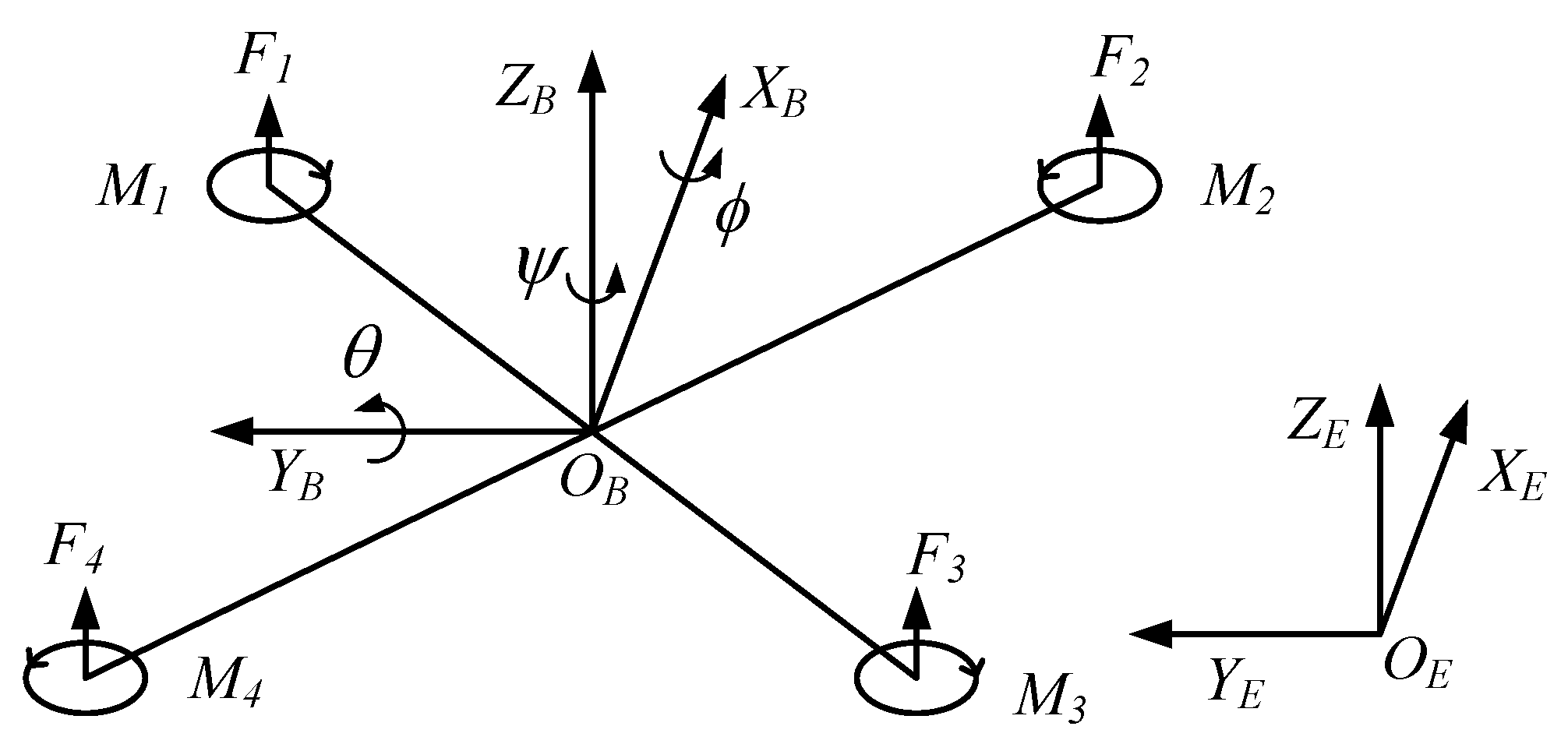
2. The Dynamic Model of Quadrotor Aircrafts

Quadrotor aircrafts usually have two kinds of structures: X-shaped structure and cross-shaped structure. The modeling results of the two structures are slightly different, but the modeling process is the same. In this paper, a quadrotor aircraft with an X-shaped structure is selected for analysis. The structure and coordinate system of the quadrotor vehicle are shown in Figure 1. Two coordinate systems are defined, which are inertial coordinate system E = ( O E , X E , Y E , Z E ) and body coordinate system B = ( O B , X B , Y B , Z B ) .
The quadrotor aircraft is an underactuated system with four control inputs and six state outputs. In the real flight environment, it is difficult to obtain the actual model precisely because of the characteristics of uncertainty, non-linearity and strong coupling. In order to obtain an approximate model of the quadrotors, the following assumptions are made for the quadrotors in this paper:
  • The quadrotor aircraft is an ideal rigid body in flight, with constant mass and no deformation in any form;
  • The mass of the quadrotor aircraft is uniformly and symmetrically distributed, and the origin of the body coordinate system always coincides with the center of gravity and center of mass of the aircraft;
  • The aircraft flies at low speeds and small angles and ignores the influence of air resistance.
Based on the above assumptions under ideal conditions, the dynamic equation of quadrotor aircraft is established according to the force analysis of the aircraft and Newton–Euler equation:
P ˙ = V m V ˙ = R B E F G J · ω ˙ = ω × ( J · ω ) + G a + M
where P and V are the position and velocity of the aircraft in the inertial coordinate system, respectively, G = [ 0 0 m g ] T , J 3 × 3 is the moment of inertia of the rotor, w is the rotational angular velocity in the body coordinate system, F is the total pull of the propeller, M is the aerodynamic torque generated by the rotor, and G a is the gyro torque generated by the rotor. For a quadrotor aircraft:
G a , ϕ = J r · ϕ ˙ · Ω G a , θ = J r · θ ˙ · Ω G a , ψ = 0
Ω = Ω 2 + Ω 4 Ω 1 Ω 3
where J r is the moment of inertia of the rotor and Ω i is the speed of the corresponding motor. The dynamic model of the quadrotor aircraft is obtained according to formula (1)–(3):
ϕ ¨ = θ ˙ ψ ˙ J y J z J x J r J x θ ˙ Ω + U 2 J x θ ¨ = ϕ ˙ ψ ˙ J z J x J y + J r J y ϕ ˙ Ω + U 3 J y ψ ¨ = ϕ ˙ θ ˙ J x J y J z U 4 J z x ¨ = ( cos ϕ sin θ cos ψ + sin ϕ sin ψ ) U 1 m y ¨ = ( cos ϕ sin θ sin ψ sin ϕ cos ψ ) U 1 m z ¨ = ( cos ϕ cos θ ) U 1 m g
where ϕ , θ and ψ are the angles of rotation around the x axis, y axis and z axis in the body coordinate system (counterclockwise); J x , J y and J z are the moment of inertia of the fuselage in three directions, respectively; m is the mass of the fuselage; g is the gravitational acceleration; U i is the virtual control quantity. For a quadrotor aircraft with X-shaped structure, U i is defined as Equation (5):
U 1 U 2 U 3 U 4 = c T ( Ω 1 2 + Ω 2 2 + Ω 3 2 + Ω 4 2 ) 2 2 d c T ( Ω 1 2 Ω 2 2 Ω 3 2 + Ω 4 2 ) 2 2 d c T ( Ω 1 2 + Ω 2 2 Ω 3 2 Ω 4 2 ) c M ( Ω 1 2 Ω 2 2 + Ω 3 2 Ω 4 2 )
where d is the arm length from the motor to the center of the aircraft, c T is the pull coefficient of the propeller, and c M is the torque coefficient.

3. The Model of Turbulent Wind Field

In order to verify the disturbance rejection performance of the designed controller, the Dryden model is selected to describe the turbulent wind field and added to the quadrotor model. Compared with other forms of turbulent wind field, the turbulent wind field of the Dryden model has the advantages of low computational cost and easy realization. The advantage is that the Dryden model only needs to input the white noise generated by the computer simulation into the designed filter to simulate the turbulent wind speed of the atmosphere.
The spectrum function of the Dryden model is [24]:
Φ u ( ϖ ) = 2 σ u 2 L u π V · 1 1 + L u ϖ V 2 Φ v ( ϖ ) = 2 σ v 2 L v π V · 1 + 12 L v ϖ V 2 1 + 4 L v ϖ V 2 2 Φ w ( ϖ ) = 2 σ w 2 L w π V · 1 + 12 L w ϖ V 2 1 + 4 L w ϖ V 2 2
where ϖ is the time frequency; V is the speed of the aircraft; Φ u ( ϖ ) , Φ v ( ϖ ) , Φ w ( ϖ ) is the power general density in u, v, w direction; σ u , σ v , σ w is the intensity of turbulence; L u , L v , L w is the scale of turbulence.
For the low-altitude environment, the turbulence scale and turbulence intensity are satisfied in Equation (7), where h is the flying height, and W 20 is the wind speed at a height of 6.096 meters.
2 L w = h L u = 2 L v = h ( 0.177 + 0.000823 h ) 1.2 σ w = 0.1 W 20 σ u σ w = σ v σ w = 1 ( 0.177 + 0.000823 h ) 0.4

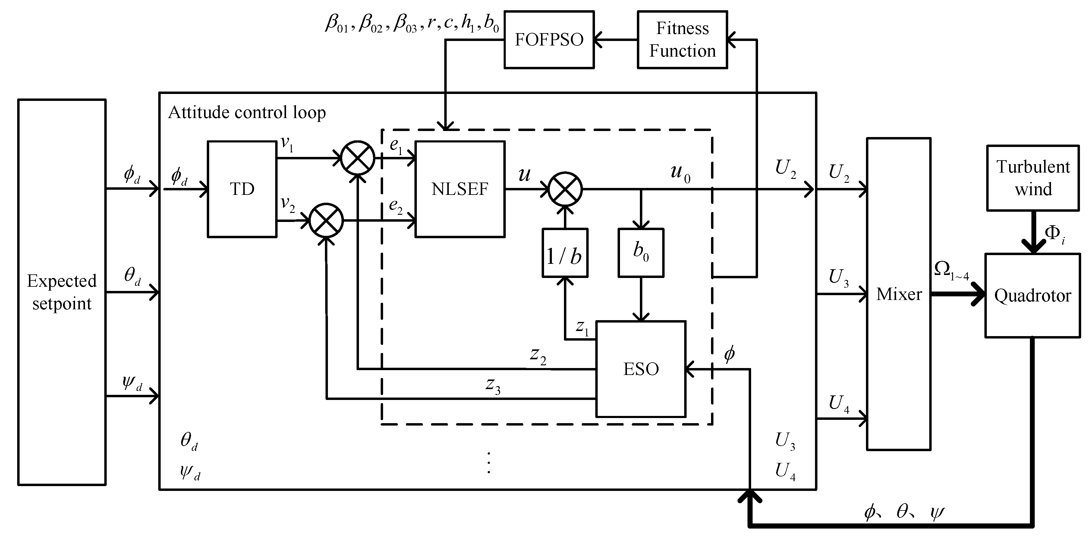
4. Design of Quadrotor Aircraft Control System Based on ADRC

According to the Formula (4), the attitude dynamics equation of the quadrotor aircraft is a second-order nonlinear coupling equation; let d x , d y and d z be unknown disturbances along the three axes, respectively, then the attitude dynamics equation can be expressed as follow:
ϕ ¨ = d x + f x ( · ) + U 2 J x θ ¨ = d y + f y ( · ) + U 3 J y ψ ¨ = d z + f z ( · ) U 4 J z
where f x ( · ) , f y ( · ) and f z ( · ) are
f x ( · ) = θ ˙ ψ ˙ J y J z J x J r J x θ ˙ Ω f y ( · ) = ϕ ˙ ψ ˙ J z J x J y + J r J y ϕ ˙ Ω f z ( · ) = ϕ ˙ θ ˙ J x J y J z
where d i + f i ( · ) is the sum of the internal and external disturbances in the system. ESO estimates the internal and external disturbances of the system and uses the estimation result as a feedback signal to dynamically compensate the control output.

4.1. Attitude Controller Structure

According to Equation (4), the translational motion of the quadrotor aircraft in three-dimensional space can be realized by changing the attitude angle. Therefore, the problem of tracking the desired trajectory of quadrotor aircraft can be realized by tracking the desired attitude angle and altitude. The structure of the attitude control system of the quadrotor aircraft based on ADRC is shown in Figure 2.

4.2. Tracking Differentiator (TD)

The TD provides a transition process for the input signal, which solves the contradiction between system overshoot and rapidity. The mathematical expression of the tracking differentiator for the second-order system is as follows:
f h = f h a n ( v 1 ( k ) v d ( k ) , v 2 ( k ) , r 0 , h 0 ) v 1 ( k + 1 ) = v 1 ( k ) + T · v 2 ( k ) v 2 ( k + 1 ) = v 2 ( k ) T · f h
where f h a n ( · ) is the fastest synthesis function [25], T is the sampling period of the control system, v d , v 1 and v 2 are the desired input signal, the desired tracking signal and the differential of the tracking signal, respectively. r 0 and h 0 are the two adjustable parameters of the TD, where r 0 is the speed factor, which increases the response speed and reduces the transition process, but if the value is too large, the tracking signal will be closer to the expected input signal and lose the meaning of the transition process. h 0 is a filter factor, increasing the value of h 0 can improve the filtering effect but also bring greater phase delay.

4.3. Extended State Observer (ESO)

The ESO does not depend on the accurate mathematical model of the control object. According to the input and output of the system, ESO estimates the total disturbance of the system (internal uncertainty and external disturbance) and compensates it to the controller. The convergence of nonlinear ESO is analyzed in the literature [26]. The mathematical expression of ESO is as follows:
ε 1 = z 1 ( k ) y ( k ) z 1 ( k + 1 ) = z 1 ( k ) + T z 2 ( k ) β 01 ε 1 z 2 ( k + 1 ) = z 2 ( k ) + T z 3 ( k ) β 02 f a l ε 1 , α 1 , δ + b u z 3 ( k + 1 ) = z 3 ( k ) T β 03 f a l ε 1 , α 2 , δ
where f a l ( · ) is a nonlinear function [25]; α 1 , α 2 are variable parameters, which determines the interval length of the linear segment of the nonlinear function; β 01 , β 02 , β 03 are determined by the sampling step of the system.

4.4. Nonlinear State Error Feedback Control (NLSEF)

The NLSEF uses the tracking error signal generated by the TD stage and the ESO stage, and it generates the control variable output through a series of nonlinear combinations. The mathematical expression of NLSEF is as follows:
e 1 = v 1 ( k ) z 1 ( k ) e 2 = v 2 ( k ) z 2 ( k ) u 0 = f h a n e 1 , c e 2 , r , h 1
The control output can be obtained by compensating for the expanded state variables observed by ESO:
u = u 0 z 3 b 0
where r is the control output gain, generally taking a larger value, c is the damping factor, h 1 is the accuracy factor, and b 0 is the compensation factor.
In summary, the parameters that need to be adjusted for the ADRC are: β 01 , β 02 , β 03 , r, c, h 1 , b 0 .

5. Particle Swarm Optimization Algorithm

5.1. Traditional Particle Swarm

Particle swarm optimization (PSO) is a meta-heuristic intelligent optimization algorithm based on social behavior heuristics, which is inspired by the foraging behavior of birds and often used in optimization problems. The update rules for the position and speed of the traditional particle swarm are as follows:
v i ( k + 1 ) = δ v i ( k ) + c 1 r 1 p i x i ( k ) + c 2 r 2 g x i ( k )
x i ( k + 1 ) = x i ( k ) + v i ( k + 1 )
where δ is the inertia weight, indicates the degree of memory of the particle’s previous velocity; c 1 and c 2 are learning factors, which are the weights of their own cognition and social cognition, respectively. The literature [27] suggests that the values of c 1 and c 2 should be between 0.5 and 2.5, where r 1 and r 2 are random numbers between 0 and 1, which are used to increase the randomness of particle search, k is the number of iterations, v i ( k ) is the speed of particle i in the k th iteration, x i ( k + 1 ) is the position of particle i in the k + 1 th iteration, p i is the historical optimal value of particle i, and g is the historical optimal value of all particles.

5.2. Fitness Function

According to the optimization principle of the particle swarm algorithm, this paper transforms the ADRC parameter optimization problem into a problem of finding a set of controller parameters within the feasible range of the parameters to minimize the fitness function value. The fitness function is used to judge the pros and cons of the iterative process of the algorithm. A reasonable choice of the fitness function is the prerequisite for the particle swarm algorithm to find the optimal value.
In this paper, according to the step response of the system, the effects of the fitness function designed by integral square error (ISE), integral time square error (ITSE), integral absolute error (IAE), integral time absolute error (ITAE) and the combination of them on the performance of the system controller are compared through experiments. Since the rising phase of ADRC is mainly affected by the TD part, based on the IAE, the designed fitness function is defined as the cumulative sum of errors between the response value and the expected value of the system during the period from the rise time to the end of the sampling period. Compared with other fitness functions, the fitness function designed in this paper makes the controller have better performance. The mathematical expression of fitness function is as follow:
J = t r T e ( t ) d t
where t r is the rising time of the step response of the system, and T is the sampling period of the system.

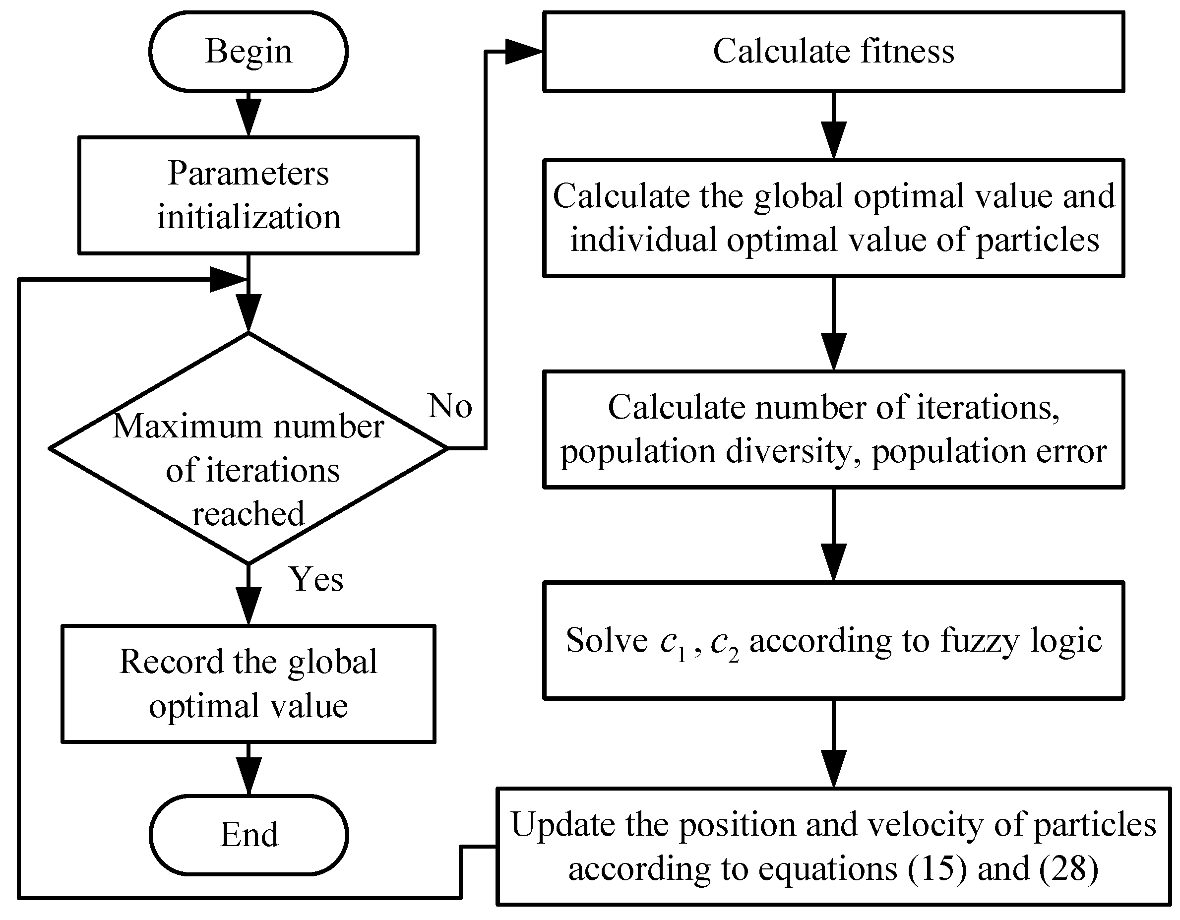
5.3. Improved Particle Swarm Optimization Algorithm

In view of the shortcomings of the traditional particle swarm optimization algorithm, such as fixed parameters, low accuracy and easy to fall into local optimal value, a fractional fuzzy particle swarm optimization algorithm is proposed in this paper to optimize the parameters of ADRC by combining the characteristics of fuzzy logic and fractional order.

5.3.1. Fuzzy System

For the traditional particle swarm optimization algorithm, the parameter c 1 or self-cognition factor indicates the importance of the particle to its previous optimal position. When c 1 = 0 , the particle will lose the diversity of the population, which will easily lead to a local optimal solution. The parameter c 2 or social cognitive factor indicates the importance of the particle to the global optimal position. When c 2 = 0 , the particles will lose the information shared by the society, and it is easy to cause the problem of the convergence speed being too slow. In the traditional particle swarm optimization algorithm, the learning factors c 1 and c 2 are fixed in the whole process of the algorithm. If the parameter values are not selected properly, it will greatly affect the performance of the particle swarm optimization algorithm. In the running process of the particle swarm optimization algorithm, adjusting the value of c 1 , c 2 dynamically will allow for better algorithm performance.
Considering the factors affecting the performance of the algorithm, this paper selects the number of iterations, population diversity and population error as the input of the fuzzy system and the learning factors c 1 and c 2 as the output of the system. The designed fuzzy system is shown in Figure 3:
The input range of the fuzzy system is 0 1 , and the output range is 0 3 . The input and output of the system are described by a triangular membership function; the input is divided into three fuzzy levels, and the output is divided into five fuzzy levels. The input and output membership functions are shown in Figure 4, and the input and output curves of the fuzzy inference system are shown in Figure 5.
The number of iterations is expressed as a percentage, which expresses the degree of iteration of the particle swarm algorithm. The normalized number of iterations is:
N I ( k ) = k M
The diversity of the population is expressed by the degree of dispersion between particles, which is obtained by measuring the average value of the Euclidean distance between each particle and the best particle. The population diversity D ( k ) is specifically as follows:
D ( k ) = 1 M i = 1 M x i ( k ) x ˙ ( k )
where x ˙ ( k ) is the global optimal particle before the k iteration. The normalized population diversity is defined as:
N D ( k ) = 0 , min ( D ) = max ( D ) D ( k ) min ( D ) max ( D ) min ( D ) , min ( D ) max ( D )
The population error is defined as the average of the sum of the difference between the fitness of each particle and the fitness of the best particle. The population error is defined as:
E ( k ) = 1 M i = 1 M F i t n e s s x i ( k ) F i t n e s s x ˙ ( k )
The normalized population error is defined as:
N E ( k ) = 0 , min ( E ) = max ( E ) E ( k ) min ( E ) max ( E ) min ( E ) , min ( E ) max ( E )
In the above formula, k is the k th iteration of the particle swarm optimization algorithm, M is the population size, and F i t n e s s ( x i ) is the fitness value of the particle i.

5.3.2. Fractional Order Particle Swarm Optimization

The fractional particle swarm algorithm combines the inherent memory characteristics of the fractional order, which can be used to record the movement trajectory of particles, thus improving the accuracy of particle solution and the speed of convergence [28,29]. Fractional calculus has many forms and can be defined by a variety of fractional derivatives, in which Grünwald–Letnikov fractional derivatives are defined as:
D α [ f ( t ) ] = lim h 0 1 h α × k = 0 + ( 1 ) k Γ ( α + 1 ) Γ ( k + 1 ) Γ ( k α + 1 ) f ( x k h )
where α is the fractional coefficient, D α [ f ( t ) ] is the α -order calculus of the function f ( t ) , and h is the calculus step. When t is discrete time, the fractional derivative can be approximated as:
D α [ f ( t ) ] = 1 T α × k = 0 r ( 1 ) k Γ ( α + 1 ) f ( x k T ) Γ ( k + 1 ) Γ ( k α + 1 )
where T is the sampling period, r is the truncation order, and the Γ function is defined as:
Γ ( z ) = 0 t z 1 e t dt
For the speed update formula, Formula (14), of the traditional particle swarm optimization algorithm, when the inertia weight δ = 1 :
v i ( k + 1 ) v i ( k ) = c 1 r 1 p i x i ( k ) + c 2 r 2 g x i ( k )
where v i ( k + 1 ) v i ( k ) is the first-order difference of velocity. When the sampling period T = 1 :
D α [ v ( t ) ] = c 1 r 1 p i x i ( k ) + c 2 r 2 g x i ( k )
According to Formula (22), when the order of truncation r = 4 , the following is obtained:
D α [ v ( k ) ] = v t + 1 α v t + 1 2 α ( α 1 ) v t 1 1 6 α ( α 1 ) ( α 2 ) v t 2 + 1 24 α ( α 1 ) ( α 2 ) ( α 3 ) v t 3
The velocity update formula of fractional particle swarm is as shown in Equation (28):
v t + 1 = α v t 1 2 α ( α 1 ) v t 1 + 1 6 α ( α 1 ) ( α 2 ) v t 2 1 24 α ( α 1 ) ( α 2 ) ( α 3 ) v t 3 + c 1 r 1 p i x i ( k ) + c 2 r 2 g x i ( k )

5.3.3. Fractional Order Fuzzy Particle Swarm

The fractional fuzzy particle swarm algorithm adds the characteristics of fuzzy logic and fractional order to the particle swarm algorithm, which improves the global and local exploration capabilities of the particle swarm algorithm, avoids particles falling into the local optimal value, and improves the accuracy of the solution. Among them, the speed update formula of the fractional fuzzy particle swarm is shown in Formula (28), and the fractional coefficient α is between 0.5 and 0.8. In this paper, according to the iterative process of particle swarm, the linear weight decreasing strategy is used to linearly adjust α , and the update strategy of α is as follows:
α = M a x _ α M a x _ α M i n _ α M a x _ I t e r × I t e r
The learning factors c 1 and c 2 in the speed update formula are dynamically updated by using the fuzzy logic described in Section 5.3.1. The solution flow of fractional order fuzzy particle swarm optimization proposed in this paper is shown in Figure 6:

6. Experimental Analysis

In order to verify the effectiveness of the proposed fractional fuzzy particle swarm in ADRC parameter optimization, this paper first designed a quadrotor system model based on ADRC on the simulation platform and selected seven adjustable parameters of the controller ( β 01 , β 02 , β 03 , r, c, h 1 , b 0 ) as an optimization goal; secondly, the designed controller is deployed on the experimental platform for verification using a model-based design method. The platform configuration used for the simulation is: Intel(R) Core(TM) i7-10700F CPU @ 2.90 GHz, 16 GB running memory.
The parameters of the quadrotor aircraft model used in the simulation are shown in Table 1. The population dimension of fractional fuzzy particle swarm is seven dimensions, corresponding to seven controller parameters to be adjusted, and the population size is 48 and the maximum number of iterations is 100. According to adjustment experience, the value range of seven parameters of ADRC is shown in Table 2.

6.1. Simulation Verification

6.1.1. Optimization Analysis of Controller Parameters

The simulation takes the pitch angle as an example (the optimization process of other attitude angles is similar). The experiment uses PSO, FPSO and FOFPSO to optimize the parameters of the controller, and it compares them with the unoptimized controller. In the experiment, the expected input control signal of the controller r ( t ) = 0.61 rad ; the experimental results are shown in Figure 7:
For the unoptimized ADRC, there is a large overshoot and steady-state error; the controller optimized by PSO and FPSO has higher performance, but there is a certain shock in the rising period, resulting in an overshoot. After the controller is optimized by the FOFPSO algorithm, the response effect of the controller is better, and there is almost no overshoot and oscillation. As ADRC arranges the transition process of the input signal in the TD phase and also tracks the transition curve based on the idea of “small error and large gain”, which directly affects the rise time of the controller response, it shows that the rise time of the four algorithms is basically the same, and the main difference lies in the overshoot and steady state value.
Figure 8 shows the process of optimizing the parameters of the quadrotor vehicle controller by PSO, FPSO and FOFPSO algorithms, respectively; the three algorithms optimize the controller with same initial value. With the increase in the number of iterations, the particles continue to find the optimal value in the feasible space. Among them, the traditional PSO algorithm has poor optimization ability, and the early global exploration ability is not strong and cannot carry out large-scale exploration. Due to the existence of fuzzy logic, FPSO has strong optimization ability in the early stage, but it is easy to fall into the local optimal value in the later stage. Lastly, the FOFPSO algorithm proposed in this paper adds the characteristic of fractional order on the basis of FPSO, the global search ability of particles is stronger, and the optimization accuracy is higher than that of PSO and FPSO.
The parameters of the optimized pitch angle controller are shown in Table 3:

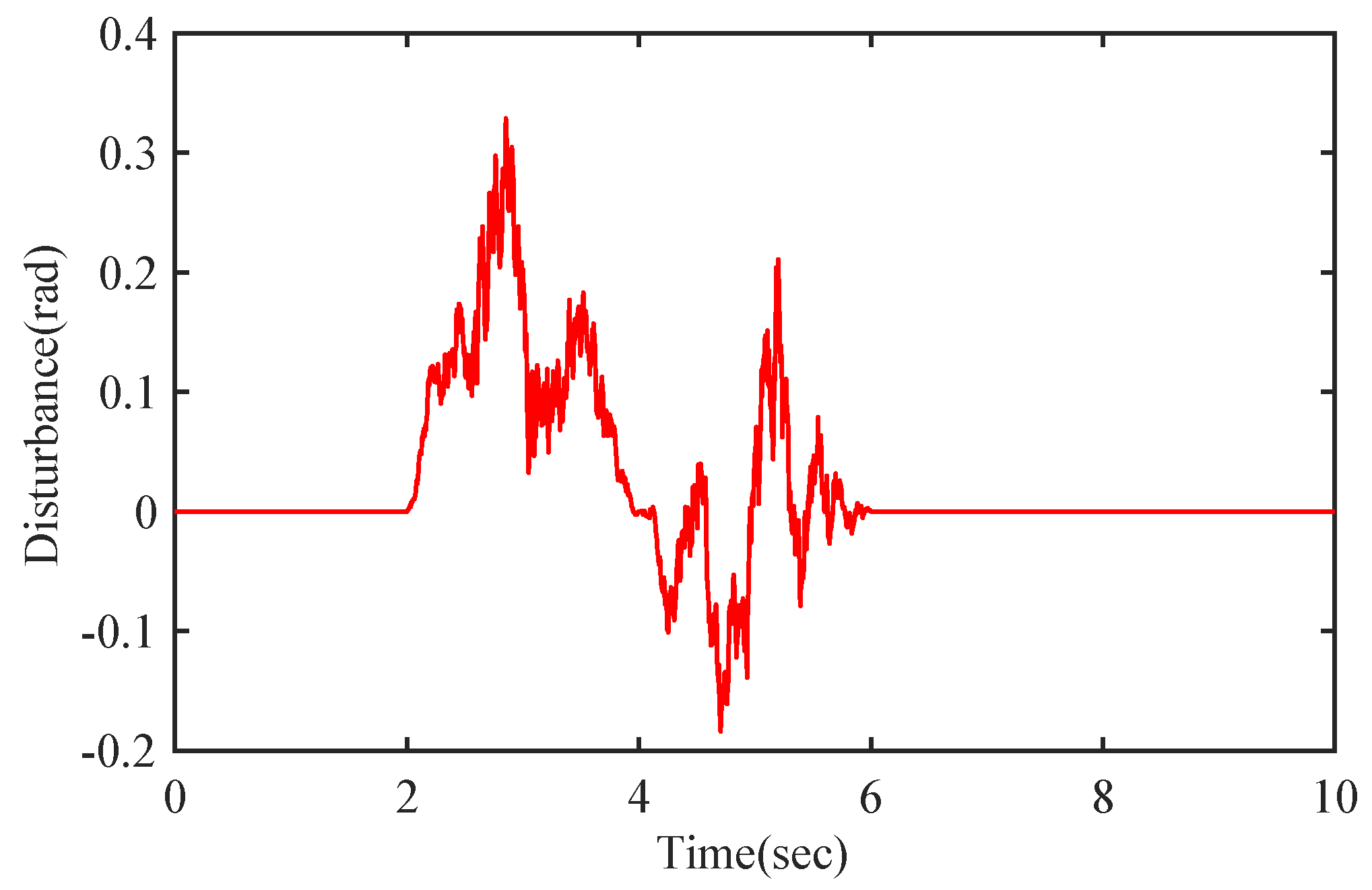
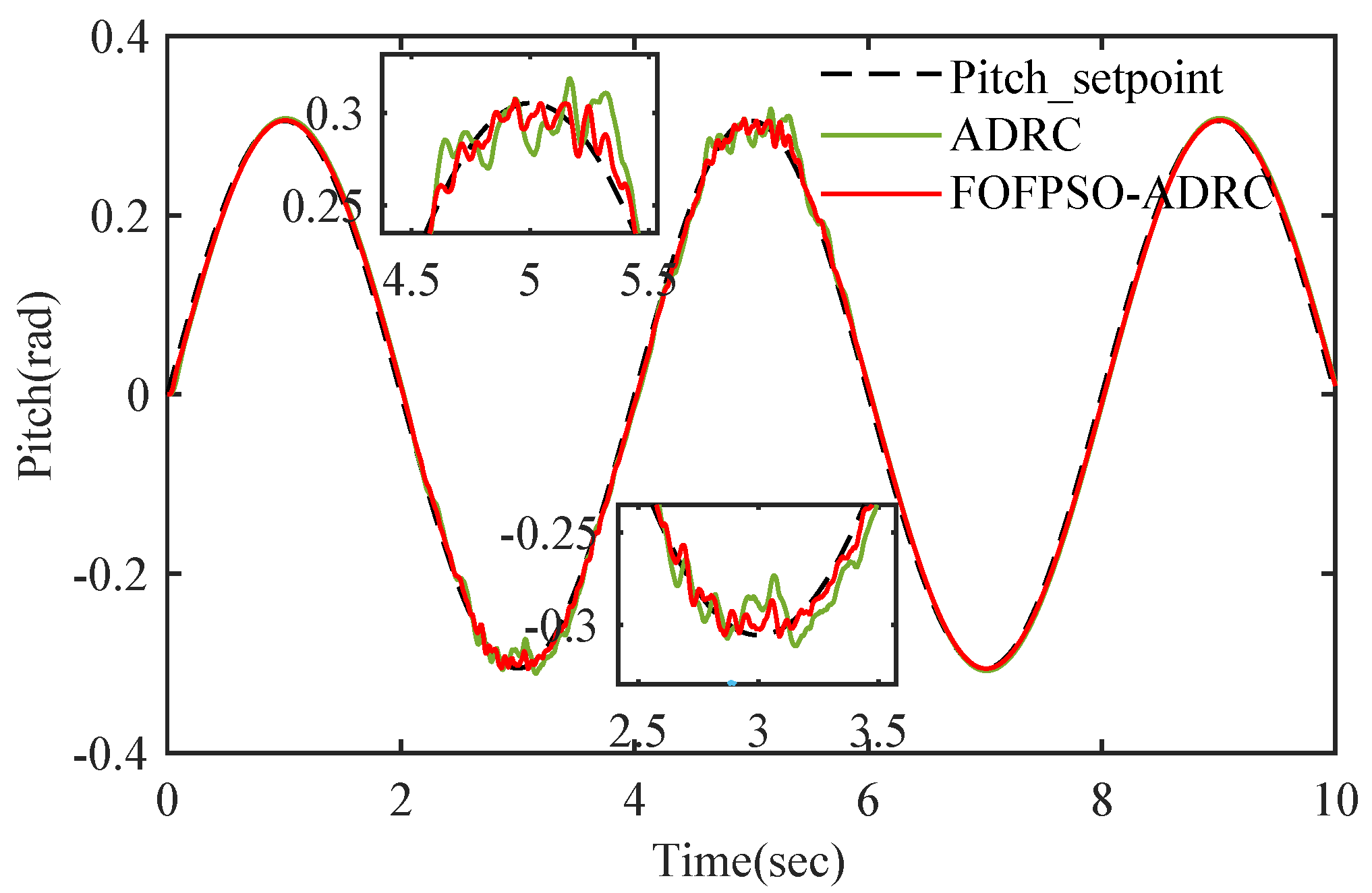
6.1.2. Controller Disturbance Rejection Performance Analysis

In order to verify the attitude tracking performance and disturbance rejection performance of the optimized ADRC controller, the attitude tracking experiment is designed, and the turbulence wind field disturbance is added to verify the attitude tracking performance and disturbance rejection performance of the controller, respectively. The experimental results are compared with unoptimized ADRC. The parameters of the unoptimized ADRC controller are shown in Table 4. The optimized controller parameters come from the optimized results of ADRC by FOFPSO algorithm mentioned in Section 6.1.1.
In the disturbance rejection performance analysis experiment, the sine signal is used as the expected signal, the amplitude is 0.31 rad and the simulation time is 10 s. During the period of 2 s to 6 s, the turbulent wind field is added. The turbulent wind field is shown in Figure 9, and the experimental results are shown in Figure 10.
The attitude response curve fluctuates greatly near 2 s and 5 s due to the interference of turbulent wind field. Among them, for attitude tracking, both ADRC and FOFPSO-ADRC can retain the stability of attitude tracking under the interference of the wind field. However, because ADRC is optimized by FOFPSO, its overshoot is smaller than that of non-optimized ADRC.
For comparison, the same method is used to test the optimum performance of PSO, FPSO, AGAPSO. The comparison results are shown in Table 5. It can be seen that the ADRC optimized by FOFPSO has less tracking deviation and RMSE.

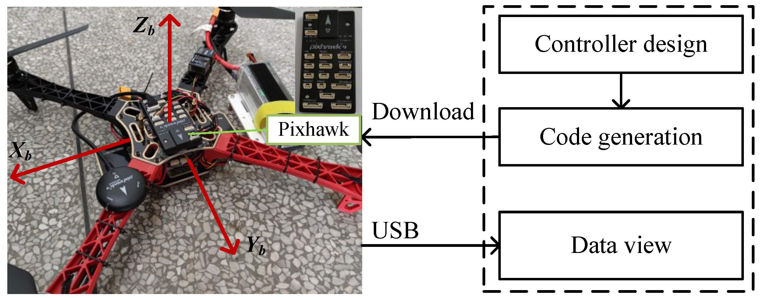
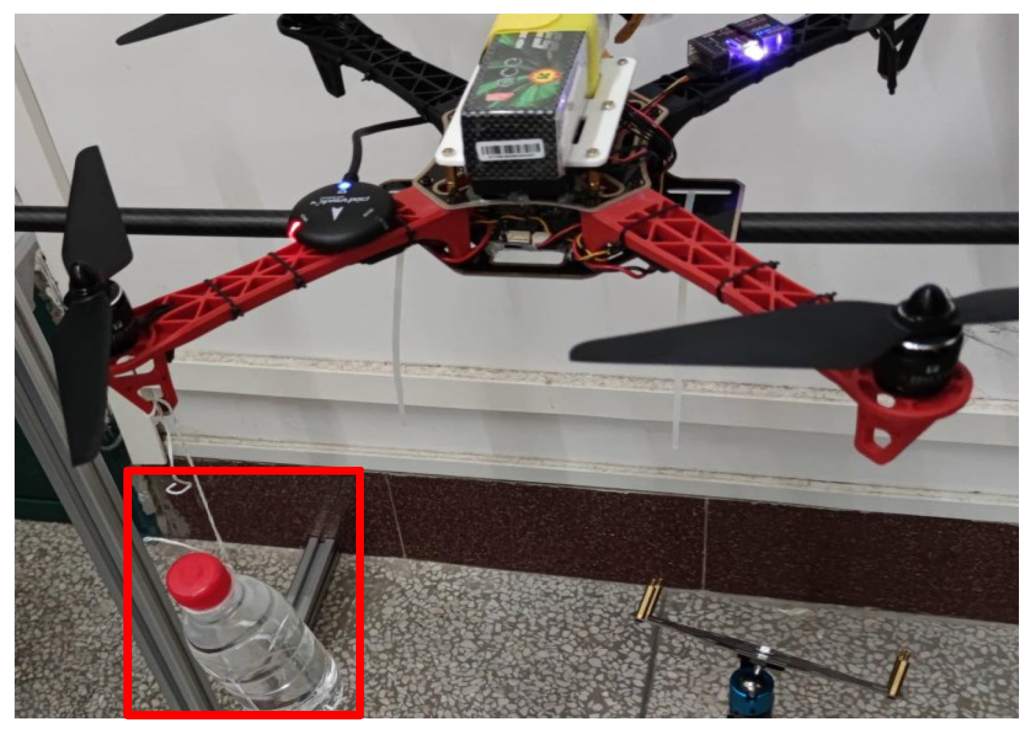
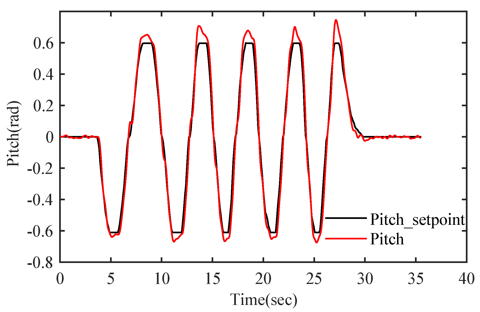
6.2. Verification of Aircraft Experimental Platform

In order to verify the feasibility of the controller on the actual quadrotor aircraft hardware platform, this paper adopts the model-based design (MBD) method to convert the designed controller into embedded programming language, compile and burn it to the Pixhawk4 flight control platform for execution. Pixhawk4 is an open source flight control platform designed by the Holybro company and Px4 team; stm32f765 is used as the main control chip, and sensors for flight control, such as gyroscope and accelerometer, are integrated. The aircraft experimental platform built in this paper is shown in Figure 11:
In the experiment, the tracking performance of the pitch angle of the quadrotor aircraft is tested, and the experimental results are shown in Figure 12.
It can be seen that the response of pitch angle can track the desired curve well, the response speed is fast, and the stable attitude tracking control can be realized. However, due to the excessive rate of expected angle change, there is a slight overshoot at the peak and valley of the expected curve, and the overshoot is within the allowable range. It shows that the designed controller can be implemented on the actual aircraft platform, and it has the performance of fast attitude tracking and a small overshoot.
In order to verify the disturbance rejection performance of the controller, the experiment tested the attitude tracking performance of the pitch angle by hanging a 380 mL water bottle on the end of any arm. The experimental environment is shown in Figure 13, and the experimental results are shown in Figure 14. The suspended water bottle will swing irregularly under the wind of the rotor, leading to an uneven force on the rotor arm. Therefore, the water bottle suspended on the arm can be considered as additional random interference—this added interference is relatively strong and with high uncertainty.
It can be seen that, under the effect of external reinforcement interference, the pitch angle of the quadrotor aircraft can still track the desired attitude curve and realize stable real-time control. Due to the swing of the water bottle driven by the wind of the rotor, there is a slight error in the attitude curve at the peak and valley of the expected attitude angle. With the sharp change of the attitude angle and the swing amplitude of the water bottle, there is a large angle error at about 27 s. The overall tracking curve is within the allowable error range and can be modified quickly, which further proves that the designed controller has a strong disturbance rejection ability and fast correction ability, and the robustness of the control system is high.

7. Conclusions

In order to improve the attitude control performance of the quadrotor, this paper first analyzes the dynamics model of the quadrotor and designs an attitude control system based on ADRC. Regarding the problem that ADRC has many parameters, it is difficult to adjust, and manual adjustment is difficult to achieve the optimal problem, this paper proposes the FOFPSO algorithm to optimize the ADRC parameters. The experimental results show that:
(1) The quadrotor UAV attitude control system based on ADRC theory has stronger control performance and disturbance rejection ability.
(2) The FOFPSO proposed in this paper has the advantages of fast convergence speed, high solution accuracy, and not easy to fall into local optimal values; ADRC optimized by the FOFPSO algorithm has better performance in attitude tracking and disturbance rejection.
(3) In order to verify the feasibility of the designed control system implemented on the aircraft experimental platform, this paper adopts a model-based design method and deploys the designed control system on the aircraft experimental platform for attitude tracking experiments and disturbance rejection experiments. The experimental results show that the designed control system has the advantages of fast tracking speed, small overshoot and strong robustness, which further demonstrates that ADRC has greater advantages in practical engineering applications.

Author Contributions

Conceptualization, Q.Z. and Y.W.; methodology, Y.W.; software, Y.W.; validation, Y.W., Q.Z. and X.L.; formal analysis, X.L.; investigation, Y.W.; resources, Q.Z.; data curation, Y.W.; writing—original draft preparation, Y.W.; writing—review and editing, Q.Z. and X.L.; supervision, Q.Z.; project administration, Q.Z.; funding acquisition, Q.Z. All authors have read and agreed to the published version of the manuscript.

Funding

This work is supported in part by the key research and development projects in Guangxi under Grant AB21076005, in part by the Project on Promoting Scientific Research Ability of Young and Middle-aged People in Guangxi under Grant 2018KY1095, in part by the Specialized Talents in Guangxi under Grant AD18281018, in part by the Guangxi Natural Science Foundation of China under Grant 2018GXNSFAA138092, in part by the Innovation Project of GUET Graduate Education under Grant 2021YCXS121, in part by the College Students’ Innovative Entrepreneurial Training under Grant C99BXM00BX87.

Conflicts of Interest

The authors declare no conflict of interest.

References

  1. Pazooki, M.; Mazinan, A.H. Hybrid fuzzy-based sliding-mode control approach, optimized by genetic algorithm for quadrotor unmanned aerial vehicles. Complex Intell. Syst. 2018, 4, 79–93. [Google Scholar] [CrossRef] [Green Version]
  2. Roberge, V.; Tarbouchi, M.; Labonté, G. Fast Genetic Algorithm Path Planner for Fixed-Wing Military UAV Using GPU. IEEE Trans. Aerosp. Electron. Syst. 2018, 54, 2105–2117. [Google Scholar] [CrossRef]
  3. Jordan, S.; Moore, J.; Hovet, S.; Box, J.; Perry, J.; Kirsche, K.; Tse, Z.T.H. State-of-the-art technologies for UAV inspections. IET Radar Sonar Navig. 2018, 12, 151–164. [Google Scholar] [CrossRef]
  4. Yang, L.; Fan, J.; Liu, Y.; Li, E.; Peng, J.; Liang, Z. A review on state-of-the-art power line inspection techniques. IEEE Trans. Instrum. Meas. 2020, 69, 9350–9365. [Google Scholar] [CrossRef]
  5. Zhang, S.; Xue, X.; Chen, C.; Sun, Z.; Sun, T. Development of a low-cost quadrotor UAV based on ADRC for agricultural remote sensing. Int. J. Agric. Biol. Eng. 2019, 12, 82–87. [Google Scholar] [CrossRef]
  6. Emran, B.J.; Najjaran, H. A review of quadrotor: An underactuated mechanical system. Annu. Rev. Control 2018, 46, 165–180. [Google Scholar] [CrossRef]
  7. Moreno-Valenzuela, J.; Pérez-Alcocer, R.; Guerrero-Medina, M.; Dzul, A. Nonlinear PID-type controller for quadrotor trajectory tracking. IEEE/ASME Trans. Mechatron. 2018, 23, 2436–2447. [Google Scholar] [CrossRef]
  8. Najm, A.A.; Ibraheem, I.K. Nonlinear PID controller design for a 6-DOF UAV quadrotor system. Eng. Sci. Technol. 2019, 22, 1087–1097. [Google Scholar] [CrossRef]
  9. Miranda-Colorado, R.; Aguilar, L.T. Robust PID control of quadrotors with power reduction analysis. ISA Trans. 2020, 98, 47–62. [Google Scholar] [CrossRef] [PubMed]
  10. Okyere, E.; Bousbaine, A.; Poyi, G.T.; Joseph, A.K.; Andrade, J.M. Lqr controller design for quad-rotor helicopters. J. Eng. 2019, 17, 4003–4007. [Google Scholar] [CrossRef]
  11. Jian, P.; Changlong, L. UAV attitude control with LQR controller based on extended state observer. J. Syst. Simul. 2018, 30, 753–759. [Google Scholar]
  12. Razmi, H.; Afshinfar, S. Neural network-based adaptive sliding mode control design for position and attitude control of a quadrotor UAV. Aerosp. Sci. Technol. 2019, 91, 12–27. [Google Scholar] [CrossRef]
  13. Islam, M.; Okasha, M.; Sulaeman, E. A model predictive control (mpc) approach on unit quaternion orientation based quadrotor for trajectory tracking. Int. J. Control. Autom. Syst. 2019, 17, 2819–2832. [Google Scholar] [CrossRef]
  14. Eskandarpour, A.; Sharf, I. A constrained error-based MPC for path following of quadrotor with stability analysis. Nonlinear Dyn. 2020, 99, 899–918. [Google Scholar] [CrossRef]
  15. Li, S.; Wang, Y.; Tan, J. Adaptive and robust control of quadrotor aircrafts with input saturation. Nonlinear Dyn. 2017, 89, 255–265. [Google Scholar] [CrossRef]
  16. Song, Z.; Wang, Y.; Liu, L.; Cheng, Z.; Yang, Y. Research on Attitude Control of Quadrotor UAV Based on Active Disturbance Rejection Control. In Proceedings of the 2020 Chinese Control And Decision Conference (CCDC), Hefei, China, 22–24 August 2020; pp. 5051–5056. [Google Scholar]
  17. Zhou, Z.; Huang, R.; Ou, X.; Wang, W.; Lei, X. Pd-adrc cascade control for quadrotor system. Syst. Eng. Electron. 2018, 40, 2055–2061. [Google Scholar]
  18. Zhao, L.; Dai, L.; Xia, Y.; Li, P. Attitude control for quadrotors subjected to wind disturbances via active disturbance rejection control and integral sliding mode control. Mech. Syst. Signal Process. 2019, 129, 531–545. [Google Scholar] [CrossRef]
  19. Lotufo, M.A.; Colangelo, L.; Perez-Montenegro, C.; Canuto, E.; Novara, C. UAV quadrotor attitude control: An ADRC-EMC combined approach. Control. Eng. Pract. 2019, 84, 13–22. [Google Scholar] [CrossRef]
  20. Shen, S.; Xu, J. Attitude Active Disturbance Rejection Control of the Quadrotor and Its Parameter Tuning. Int. J. Aerosp. Eng. 2020, 2020, 8876177. [Google Scholar] [CrossRef]
  21. Cai, Z.; Lou, J.; Zhao, J.; Wu, K.; Liu, N.; Wang, Y.X. Quadrotor trajectory tracking and obstacle avoidance by chaotic grey wolf optimization-based active disturbance rejection control. Mech. Syst. Signal Process. 2019, 128, 636–654. [Google Scholar] [CrossRef]
  22. He, H.; Duan, H. A multi-strategy pigeon-inspired optimization approach to active disturbance rejection control parameters tuning for vertical take-off and landing fixed-wing UAV. Chin. J. Aeronaut. 2021. [Google Scholar] [CrossRef]
  23. Zhou, X.; Gao, H.; Zhao, B.; Zhao, L. A GA-based parameters tuning method for an ADRC controller of ISP for aerial remote sensing applications. ISA Trans. 2018, 81, 318–328. [Google Scholar] [CrossRef]
  24. Beal, T.R. Digital simulation of atmospheric turbulence for Dryden and von Karman models. J. Guid. Control. Dyn. 1993, 16, 132–138. [Google Scholar] [CrossRef]
  25. Han, J. From PID to active disturbance rejection control. IEEE Trans. Ind. Electron. 2009, 56, 900–906. [Google Scholar] [CrossRef]
  26. Guo, B.Z.; Zhao, Z.L. On the convergence of an extended state observer for nonlinear systems with uncertainty. Syst. Control. Lett. 2011, 60, 420–430. [Google Scholar] [CrossRef]
  27. Engelbrecht, A.P. Fundamentals of Computational Swarm Intelligence, 1st ed.; John Wiley & Sons, Inc.: Hoboken, NJ, USA, 2006. [Google Scholar]
  28. Pires, E.S.; Machado, J.T.; de Moura Oliveira, P.B.; Cunha, J.B.; Mendes, L. Particle swarm optimization with fractional-order velocity. Nonlinear Dyn. 2010, 61, 295–301. [Google Scholar] [CrossRef] [Green Version]
  29. Zameer, A.; Muneeb, M.; Mirza, S.M.; Raja, M.A.Z. Fractional-order particle swarm based multi-objective PWR core loading pattern optimization. Ann. Nucl. Energy 2020, 135, 106982. [Google Scholar] [CrossRef]
Figure 1. Structure and coordinate system of quadrotor aircraft.
Applsci 11 11583 g001
Figure 2. The structure of the control system.
Applsci 11 11583 g002
Figure 3. Fuzzy system.
Applsci 11 11583 g003
Figure 4. Input–output membership function of fuzzy system.
Applsci 11 11583 g004
Figure 5. Input–output curve of fuzzy system.
Applsci 11 11583 g005
Figure 6. The flow chart of FOFPSO algorithm.
Applsci 11 11583 g006
Figure 7. Step response curve of pitch angle.
Applsci 11 11583 g007
Figure 8. Iterative curve of global optimal value.
Applsci 11 11583 g008
Figure 9. Turbulence.
Applsci 11 11583 g009
Figure 10. Attitude tracking curve.
Applsci 11 11583 g010
Figure 11. The experiment platform of quadrotor UAV.
Applsci 11 11583 g011
Figure 12. The tracking curve of pitch angle.
Applsci 11 11583 g012
Figure 13. The experiment platform of disturbance rejection.
Applsci 11 11583 g013
Figure 14. The tracking curve of pitch angle with disturbance.
Applsci 11 11583 g014
Table 1. Model parameters of quadrotor aircraft.
Parameter SymbolPhysical MeaningValueUnit
mTotal mass of quadrotors1.4 kg
dRotor arm length0.225 m
J x X-axis moment of inertia0.0211 kg · m 2
J y X-axis moment of inertia0.0219 kg · m 2
J z X-axis moment of inertia0.0366 kg · m 2
C t Propeller pull coefficient1.022 × 10 5 N / ( rad / m ) 2
C m Torque coefficient1.401 × 10 7 N · m / ( rad / m ) 2
Table 2. Parameter range of ADRC.
ParameterRange of ValueParameterRange of Value
β 01 1 500 c 1 400
β 02 1 4000 h 1 1 400
β 03 1 8000 b 0 1 100
r 1 400
Table 3. Optimized parameters of ADRC.
ParameterValueParameterValue
β 01 81c225
β 03 1695 h 1 210
β 04 6709 b 0 48
r215 h 0 0.004
r 0 20
Table 4. Unoptimized parameters of ADRC.
ParameterValueParameterValue
β 01 250c5
β 02 2000 h 1 200
β 03 3000 b 0 47.4
r25 h 0 0.004
r 0 20
Table 5. Attitude tracking performance.
AlgorithmMax Deviation (Rad)RMSE
ADRC0.04420.0111
PSO-ADRC0.04250.0093
AGAPSO-ADRC0.03840.0081
FPSO-ADRC0.02490.0077
FOFPSO-ADRC0.02100.0071
Publisher’s Note: MDPI stays neutral with regard to jurisdictional claims in published maps and institutional affiliations.

