Article

Improving the Manipulability of a Redundant Arm Using Decoupled Hybrid Visual Servoing

by
Alireza Rastegarpanah
1,2,*,†,
Ali Aflakian
1,2,† and
Rustam Stolkin
1,2
1
Department of Metallurgy & Materials Science, University of Birmingham, Birmingham B15 2TT, UK
2
The Faraday Institution, Quad One, Harwell Science and Innovation Campus, Didcot OX11 0RA, UK
*
Author to whom correspondence should be addressed.
Alireza Rastegarpanah and Ali Aflakian contributed equally to this work.
Appl. Sci. 2021, 11(23), 11566; https://doi.org/10.3390/app112311566
Submission received: 25 October 2021 / Revised: 23 November 2021 / Accepted: 29 November 2021 / Published: 6 December 2021
(This article belongs to the Special Issue Intelligent Robotics)

Abstract

:
This study proposes a hybrid visual servoing technique that is optimised to tackle the shortcomings of classical 2D, 3D and hybrid visual servoing approaches. These shortcomings are mostly the convergence issues, image and robot singularities, and unreachable trajectories for the robot. To address these deficiencies, 3D estimation of the visual features was used to control the translations in Z-axis as well as all rotations. To speed up the visual servoing (VS) operation, adaptive gains were used. Damped Least Square (DLS) approach was used to reduce the robot singularities and smooth out the discontinuities. Finally, manipulability was established as a secondary task, and the redundancy of the robot was resolved using the classical projection operator. The proposed approach is compared with the classical 2D, 3D and hybrid visual servoing methods in both simulation and real-world. The approach offers more efficient trajectories for the robot, with shorter camera paths than 2D image-based and classical hybrid VS methods. In comparison with the traditional position-based approach, the proposed method is less likely to lose the object from the camera scene, and it is more robust to the camera calibrations. Moreover, the proposed approach offers greater robot controllability (higher manipulability) than other approaches.

Graphical Abstract

1. Introduction

Vision sensors are widely used to provide contactless knowledge about the environment. Adjusting the behaviour of robots to cope with uncertainties of unstructured environments is one of the main applications of vision sensors in industry [1]. The classical control laws are mostly formulated by minimizing a task function that corresponds to the achievement of a given goal. Typically, this primary role only concerns the location of the robot in relation to a goal, while the environment of the robot will not be taken into account. To incorporate servoing into a complex real-world robotic system, the control law must also ensure that unfavourable configurations are avoided, such as joint limits, kinematic singularities and occlusions [2]. Visual control, also known as visual servoing (VS), essentially consists of using data from one or more cameras as input to real-time closed-loop control schemes. The objective of VS is to control the movements of a dynamic system so that it achieves a task defined by a collection of visual constraints [3]. VS helps to modify the system in order to compensate for the deficiencies and to relax the mechanical inaccuracy of the robot [3].
Controlling a robot using the image information has been the focus of a number of studies in the field of robotics and automation. There are a number of research studies that applied VS for solving industrial challenges and human-robot cooperation [4,5,6,7,8]. However, VS introduces new complexities in the image-space, joint space, and the intersection of these two; all of which must be considered [9].
Image-based or 2D VS (IBVS), Position-based or 3D VS (PBVS), and Hybrid or 2 & 1/2D VS (HVS) are three main categories of VS control approaches. The IBVS method computes the feedback directly from extracted image-space features. This method is more resistant to the camera calibration and robot kinematic errors [10]. Additionally, image features are less likely to be lost from the image screen [11]. On the other hand, IBVS has some disadvantages; for instance, some controller commands are not physically executable for the robot (out of robot reachability) [12]. The poor conditioning of the image Jacobian matrix (Interaction matrix) might cause problems with the feature error convergence, like singularities and local minima [13]. Due to direct measurement of the camera velocities from the task space errors in the PBVS process, the interaction matrix problems (i.e., local minima and singularity) are avoided, and thus feasible trajectories for the robot can be generated [14]. In addition, any error in the camera calibration may create an error in 3D estimation of the target and consequently affects the entire tracking task [3].
In order to overcome the drawbacks of classical VS methods, we proposed Decoupled Hybrid Visual Servoing (DHVS) method, which has a better controllability (higher manipulability) than other VS methods. The efficacy of the proposed method has been investigated in a sorting application (Figure 1) and it is detailed in Section 4.4. It should be mentioned that manipulability refers to the attribute of being controllable by motions of the manipulator [15]. The proposed framework is outlined in Figure 2 and detailed in Section 2.4.

1.1. Related Works

Hybrid Visual Servoing was developed to combine the benefits of IBVS and PBVS while avoiding their drawbacks [16]. Switching approach is a hybrid visual servoing technique in which the controller alternates between IBVS and PBVS based on the efficacy of the system [17]. However, when switching occurs the controller suffers from discontinuities, particularly when the object is close to the image borders [18]. Task sequencing techniques provide a solution to fill such gaps [19], nevertheless sequencing techniques make the convergence time up [3]. Furthermore, two failures in IBVS (i.e., camera retreat and Chaumette Conundrum) could not be easily identified because image-Jacobian is not ill-conditioned in those configurations [12,13]. As a result, switching between IBVS and PBVS can not resolve these issues. The Chaumette Conundrum could not be solved even by creating rotational motions around the camera optic axis, since they would cancel out each other [13].
In [13], Corke et al. proposed a visual servoing method that decouples the translation and rotation about Z-axis, from the image-Jacobian in order to address the Chaumette Conundrum and the camera retreat. However, expensive computation of the pseudo-inverse is still challenging. To fix the Chaumette Conundrum and the camera retreat, a visual servoing method was proposed that decouples translation and rotation around the Z-axis from the image-Jacobian [13]. However, compensating for rotation errors in the picture plane about the X and Y axes also results in excessive motion for the robot joints  which is undesirable [17]. By decomposing translations from rotations in 2 and 1/2D visual servoing methods, unnecessary motions are reduced [20]. These methods, however, are computationally intensive and necessitate homography construction, which is susceptible to image noise [13]. Another disadvantage of the 2 and 1/2D VS approach is that it necessitates the use of co-planar features in order to estimate the homography matrix. Otherwise, at least 8 visual features are required to make this estimation, while 4 features are sufficient in other methods [21]. The 2 and 1/2D VS approach also decomposes homography to remove rotational parameters associated with non-unique solutions [22]. In case of using static arm manipulators, issues like unfavourable configurations, joint limits, kinematic singularities and occlusions should be avoided.
Redundant robots are preferable because adding redundancy to the robot increases the manipulability and versatility [23]. There are a number of studies that investigated the use of redundancy to define various types of constraints by integrating secondary tasks that express the constraints with the main task [24,25,26]. A global objective function is used in [27] to determine a balance between the main task and the secondary tasks by using the redundant DOFs of the robot with respect to the main task. However, significant perturbations may be occurred by the obtained motions which are generally incompatible with the main task. In another classical method [28], the authors employed a gradient projection method to solve the redundancy resolution; nonetheless, this approach necessitates that the main task will not constrain all DOFs of the robot. In such cases, the main Jacobian will gain full rank, and there would be no redundancy space left for projecting any constraint. This is a drawback of the traditional gradient projection technique. In [23], a projection operator for the redundant systems was proposed based on a task function specified as the norm of the usual error; in this approach, even if the main task is full rank, this projection operator allows the secondary tasks to be completed.

1.2. Contributions of This Study

To address the aforementioned convergence and performance issues, we proposed an optimised VS process called Decoupled Hybrid Visual Servoing (DHVS). In the proposed method, two separate controllers combined together, one using 3D reconstruction of visual features and the other one directly using 2D information of image (detailed in Section 2.4). The main findings of the study are summarised as follows:
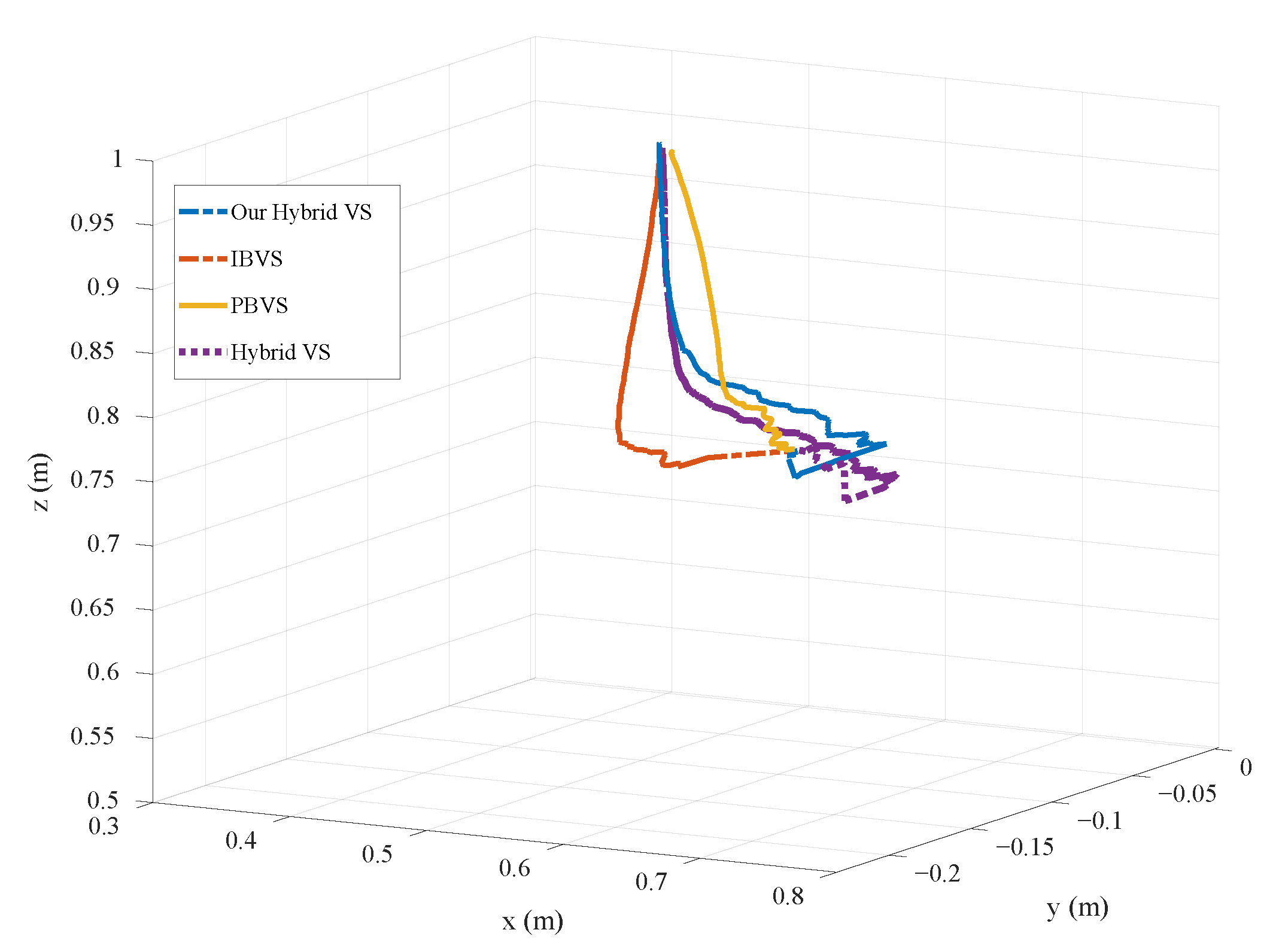
  • In terms of the convergence time and tracked distance, the proposed approach produces a more optimised trajectory in both the image-space and the joint space than other classical image-based, position-based and hybrid methods.
  • The proposed approach produces more controllable trajectories (higher manipulability) for the robot than IBVS when tracking objects.
  • In comparison to PBVS and HVS approaches, DHVS approach is less likely to lose the object from the camera Field of View (FOV).
  • The VS process has been boosted by using adaptive gains.
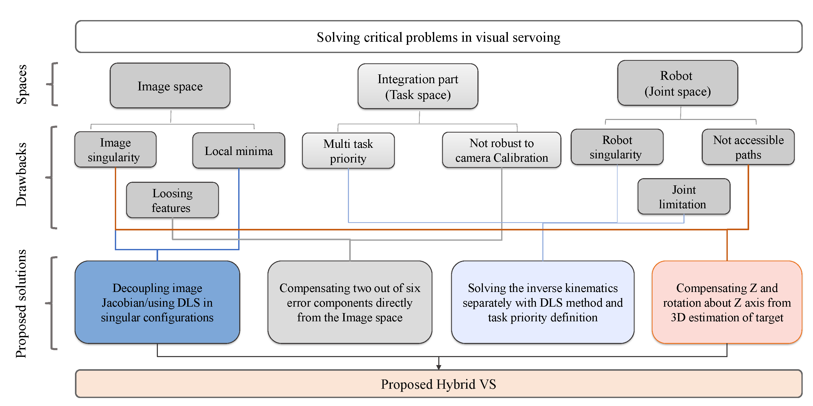
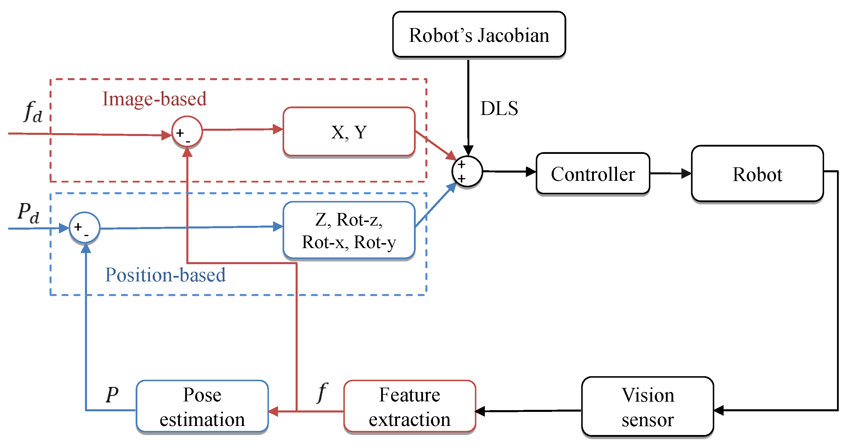
  • The effect of robot singularity is minimised by using Damped Least Square method (DLS); it helps to smooth out the discontinuities caused by the decoupling process of the image Jacobian and using adaptive gains.
  • The functionality of the manipulator has been increased by defining the manipulability as secondary task.
Figure 2 illustrates the contributions of the proposed hybrid VS approach in the image space, joint space and the interaction of these two. The proposed DHVS approach will be explored in-depth in Section 2.4, and its effectiveness will be compared with the other methods in both simulation and the real world (Section 4).
The rest of this research is as follows: A brief overview of various visual servoing controllers has been investigated in Section 2. Section 3 explains the simulation and experimental setups designed to evaluate the performance of the proposed DHVS method. In Section 4, the behaviour and effective parameters of four VS methods have been investigated. Finally, this work is concluded in Section 5 and future works are discussed.

2. Methodology

In this section, a brief background about the classical visual servoing methods is given first. Thereafter, our proposed DHVS method will be explained in detail.

2.1. Image-Based Visual Servoing (IBVS)

In the IBVS method, the feedback from the image features will be directly used and the image-Jacobian (Interaction matrix L i ) would be used to relate the pixel velocity to the camera velocity [29]. The Interaction matrix for the ith feature would be defined as follows [29]:
L i = f Z 0 u Z u v f f 2 + u 2 f v 0 f Z v Z f 2 + v 2 f u v f u
where f denotes the focal length of the camera and s = ( u , v ) denotes the coordinates of a point in the image plane. Lets consider e i is difference between current and desired positions of each feature in the image plane, and  v c a m = ( v c , w c ) is the camera velocity vector (where v c = ( v x , v y , v z ) is camera linear velocity vector, and  w c = ( w x , w y , w z ) ) is its angular velocity vector. The exponential decoupled decrease of the error can be obtained when the Interaction matrix at the desired pose is not singular (i.e., s i ( t ) s i d ( t ) = e i ( t ) = 0 ). Therefore, the appropriate camera velocity vector will be determined using the following control law [29]:
v c w c = k i L i + e i
where k i represents a positive proportional gain and L i + represents the pseudo-inverse of  L i .

2.2. Position-Based Visual Servoing (PBVS)

The feedback in PBVS comes from the pose reconstruction of the environment. The reconstructed pose will be estimated using the Euclidean methods and camera parameters. In this approach, the controller is identified as [21]:
v c w c = λ p L p 1 e p
where λ p is a positive gain and e p is the position difference (error) between the 3D estimated position of the camera and the desired 3D position of the camera. Furthermore, L p ( t ) is a 6 × 6 matrix defined in [21].

2.3. Hybrid Visual Servoing (HVS)

In order to achieve the convergence goal, the classical Hybrid (Homography-based) visual servoing approaches decompose the 6-DoF motion of the camera into two separate controllers; one for the translational components and another for the rotational components.
The translation and rotation controllers are derived as follows [9]:
w c = k L ω 1 e ω = k e ω
v c = L v 1 k e v k L v ω e ω
where, L v , L ω , and  L v ω are 3 × 3 matrices defined in [9].

2.4. Decoupled Hybrid Visual Servoing

The proposed DHVS method decouples the Z-axis of translational velocity and the three rotational velocities (the components that create the IBVS singularity and unnecessary motions for the robot) from the image-Jacobian matrix. The translational velocities of X and Y components will be measured in 2D, while the error of the other four parameters will be calculated by 3D estimation of the target. The control rule in the classic IBVS system is defined as bellow:
s ˙ = L i v c a m
By decoupling the interaction matrix, the control law would be amended as follows:
s ˙ = L x y v x y + L r v r
where v x y = [ v x v y ] T and v r = [ v z w x w y w z ] T . In addition, L x y and L r are calculated as follows:
L x y = f Z 0 0 f Z
L r = u Z u v f f 2 + u 2 f v v Z f 2 + v 2 f u v f u
Hence:
v x y = L x y + s ˙ L r v r
since the time variation of the features are related to the feature errors s ˙ = k e , therefore (10) will change to:
v x y = L x y + k ( e ) e L r v r
To reduce the convergence time, the following adaptive representation of the controller gain has been implemented [30]:
k ( e ) = ( k ( 0 ) k ( ) ) e k ( 0 ) k ( 0 ) k ( ) e + k ( )
In (12), for small amounts (less than 0.005 m) of e the positive amount of gain is k 0 = k ( 0 ) , while for the high amounts (more than 0.005 m) of e the gain is k = k e , k ( e ) , and the slope of k at e = 0 is k 0 .
The term L r v r will be calculated during each iteration, and the outcome of this term will be placed in (11). To determine v r in the PBVS method the same scenario for the IBVS method will happen as follows:
s p ˙ = L P x y v x y + L P r v r
where L P x y is a matrix generated by the first and second columns of L P in (3), and  L P r is a matrix created by the last three columns of L P in (3). Therefore:
v r = L P r + k ( e ) e p L P x y v x y
The camera velocity vector can be calculated by solving (11) and (14), simultaneously.

2.5. Robot Kinematics with Task Priority

Joint velocities ( q ˙ ) are computed after the end-effector (EE) velocities calculated using the kinematics of robot:
q ˙ = J λ ξ c e v c a m c
The transformation matrix ξ c e is used to map the velocities represented in the robot end-effector (EE) frame to the camera frame [31]:
ξ c e = R c e s k t c e R c e 0 R c e
where t c e is the translation vector between the EE frame and the camera frame. R c e is the rotation matrix between the EE and the camera frame, and  s k ( t c e ) is the skew-symmetric matrix of the translation vector. It is worth mentioning that ξ c e is constant in such a scenario (Eye-in-Hand configuration). By using this approach the effect of robot singularity has been reduced, and discontinuities caused by decoupling process have been greatly smoothed, thanks to the DLS inverse [32]:
J λ = J T J J T + λ 2 I 1
where λ is a positive scalar known as damping factor. Using DLS inverse minimizes the term J q ˙ x ˙ 2 + λ 2 q ˙ 2 . Choosing λ will ensure that the solution norm stays within an assigned range [33]. It is worth noting that regularisation techniques help with reducing the effect of singularity configurations. In addition they increase the convergence time [34]. In this study, the task priority for the given tasks (i.e., feature error convergence and robot manipulability) is calculated [32], and given by:
q ˙ = J λ ξ c e v c a m c + ( I J λ J ) q 0 ˙
where I J λ J is the Null space projection matrix. Therefore, the closest point in the Jacobian matrix null space will be identified, satisfying both tasks. q 0 ˙ is defined as follows [23]:
q ˙ 0 = k 0 w ( q ) q T
In (19), k 0 is a positive gain and w is the cost function for another task. w should be maximized in order to consider the other objectives. As mentioned earlier, the manipulability of the robot has been considered as the second task.
w ( q ) = det J ( q ) J T ( q )
Using the classical projection operator defined in [23], the secondary task will be computed and will be added to the joint velocity vector. The value of w ( q ) is called manipulability value and shows the functionality of the robot in each configuration. The more the amount of m, the better adjustment in the workspace is possible (greater range of possible motions) [35].
The proposed visual servoing control DHVS schema is depicted in Figure 3. The red blocks represent the image-based control loop, the blue blocks represent the position-based control loop, and the grey blocks represent the task-space control loop. As shown in the control block diagram in Figure 3, the camera velocities have been decoupled; in 2D, two of them (translations in X and Y) were considered by using the features created from the image screen, as feedback.The remaining components were modelled in 3D (computed by partial 3D reconstruction of the environment attained by the extracted features). Following that, the computed velocities will be given to the robot. The controller will exchange the desired camera velocities with the desired joint velocities using the Jacobian of the robot. To minimise the effects of robot singularity, the DLS inverse method was used instead of the pseudo-inverse approach. By using DHVS the object is less likely to be lost and the method is more robust against calibration than the PBVS method since two out of six camera velocities will be created directly from the image space. The 3D calculation of the visual features is used to regulate the errors of rotations and translation in the Z-axis. As a result, feasible trajectories for the robot will be generated, and image singularities caused by these four components in the interaction matrix will be eliminated. In Algorithm 1, the pseudocode of the proposed approach has been illustrated.
Algorithm 1: Decoupled hybrid visual servoing.
Applsci 11 11566 i001
The inputs of the algorithm are the feature errors in the image screen and their counterparts in the 3D space. The output of the DHVS algorithm will be the vector of joint velocities. In line 8 of Algorithm 1, the decoupled matrices will be determined from (8) and (9). Camera velocity would be estimated in lines 14 and 16 using the calculated decoupled matrices in line 8. Adaptive representation of the controller gains was used in this calculation to increase the VS task speed. Eventually, the robot joint velocities will be measured and commanded to the robot velocity controller in line 23 of Algorithm 1. Not to mention that the controller would use manipulability as a secondary task in measuring the joint velocities, and DLS inverse would be used instead of pseudoinverse to convert EE velocities to the joint velocities. Using DLS would assist the controller in reducing the impact of discontinuities and limiting the impact of singularities.

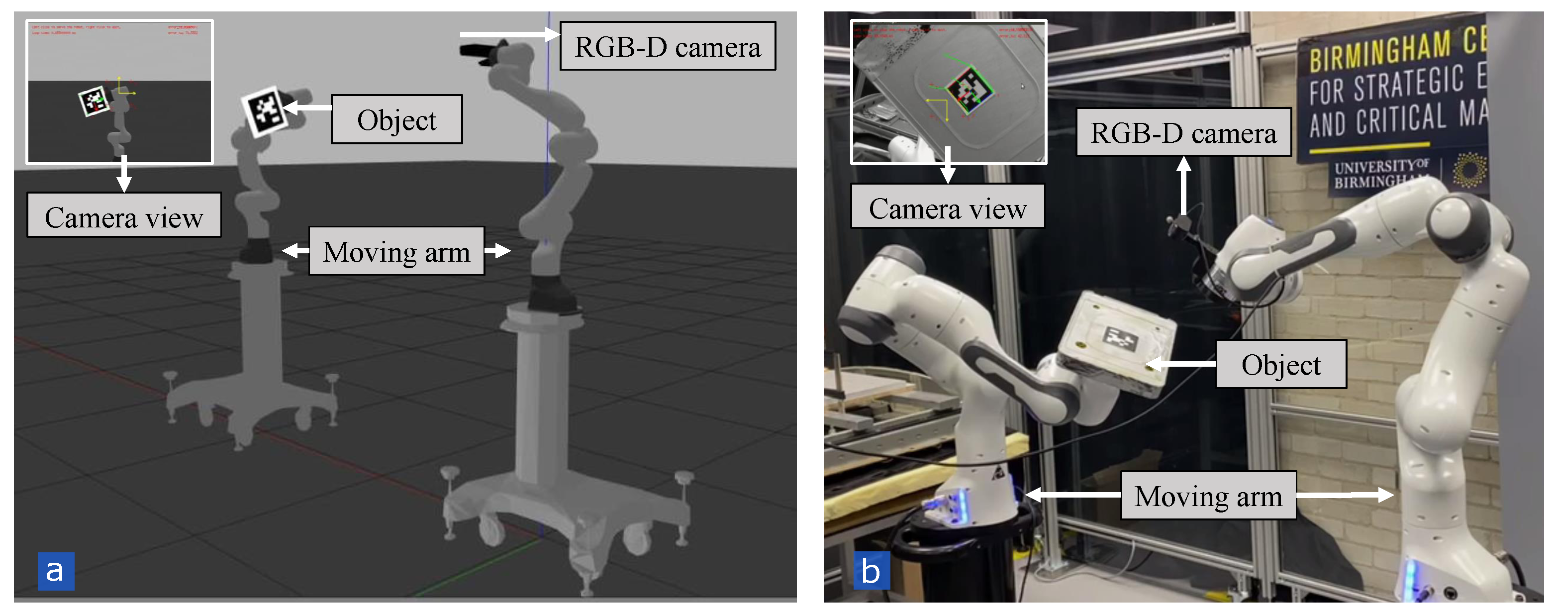
3. Simulation and Experimental Setup

In this study, two different setups were introduced to evaluate the efficacy of the proposed DHVS method in comparison with other VS methods. In the first setup, different behaviours of the proposed DHVS method have been studied such as singularity, performance and manipulability (Figure 4). The second setup was also designed to demonstrate the capability of the proposed DHVS method for performing an industrial application (i.e., sorting) (Figure 1). It is worth mentioning that all the case studies were performed with the same adaptive and DLS gains ( k 0 = 4 , k = 0.4 , k 0 = 30 , λ = 0.1 ).

3.1. Design of Setup 1

In the first setup, the DHVS method has been tested in simulation and then validated in the real world. The simulation platform includes two Franka manipulators; one robot is equipped with a RGB-D camera, and another robot arm holds an object (with a printed tag marker). Four corners of the marker are used as points of interest/visual features in this study. Tracking the object under this condition has been tested via different VS methods. The experimental and simulation setups are identical. Franka robots have 7 degrees of freedom across 7 axes, with 3 kg payload, and positioning accuracy of +/−0.1 mm in all directions. The proposed method was modelled in simulation using ROS/Gazebo. ROS Melodic on Linux 18 was used for both the simulation and the experiment. The joint state controller was used to publish the joint state (at rate of 1 kHZ) and the joint velocity group controller was used to set the joint velocities computed from the VS approaches. A system with the following CPU specification was used for the visual servoing operation: AMD Ryzen 7 3700x, 8-core with 16 CPU Threads, 3.6 GHz base clock and 36 MB total cache. Figure 4a depicts an snapshot of the developed simulation environment in Gazebo, and Figure 4b shows the identical experimental setup in the real world.
By using Setup 1, three different case studies have been designed to compare different behaviours of the DHVS method such as singularity, performance and manipulability with other VS methods.

3.1.1. Case Study 1

To demonstrate the effectiveness of the proposed DHVS method in singular configurations, this case study has been designed in which the robot with attached marker moved to a pre-defined position and another robot, equipped with the camera, tracked the visual features. The position was set in which the desired features rotate 90 around the Z-axis. Deliberately, the position was defined in which the robot encounters singularities in order to investigate if the proposed DHVS method has capability of avoiding such singularities. In addition, the camera calibration was intentionally degraded by 20% to evaluate the performance of DHVS in an imperfect calibrated condition.

3.1.2. Case Study 2

In this case study, a comprehensive comparison between the effective parameters in VS is carried out. Ten random positions were defined for the object (with attached marker) in order to be tracked by another robot (with the attached camera) using different VS methods. The experiments are performed under the same condition for all four VS approaches (IBVS, PBVS, HVS, DHVS). Thereafter, the performance of the robot and the VS methods in the image space and Cartesian space were compared quantitatively based on the RMSE, range of feature error, required number of iteration for convergence and the manipulability of the robot.

3.1.3. Case Study 3

In this case study, the object is not fixed (in opposite of Case study 1 and Case study 2) and the controller will track a dynamic object to demonstrate how DHVS could improve the manipulability of the robot (Figure 4). The selected trajectory includes all rotations and translations.

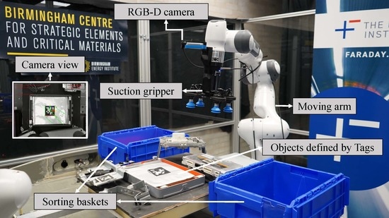
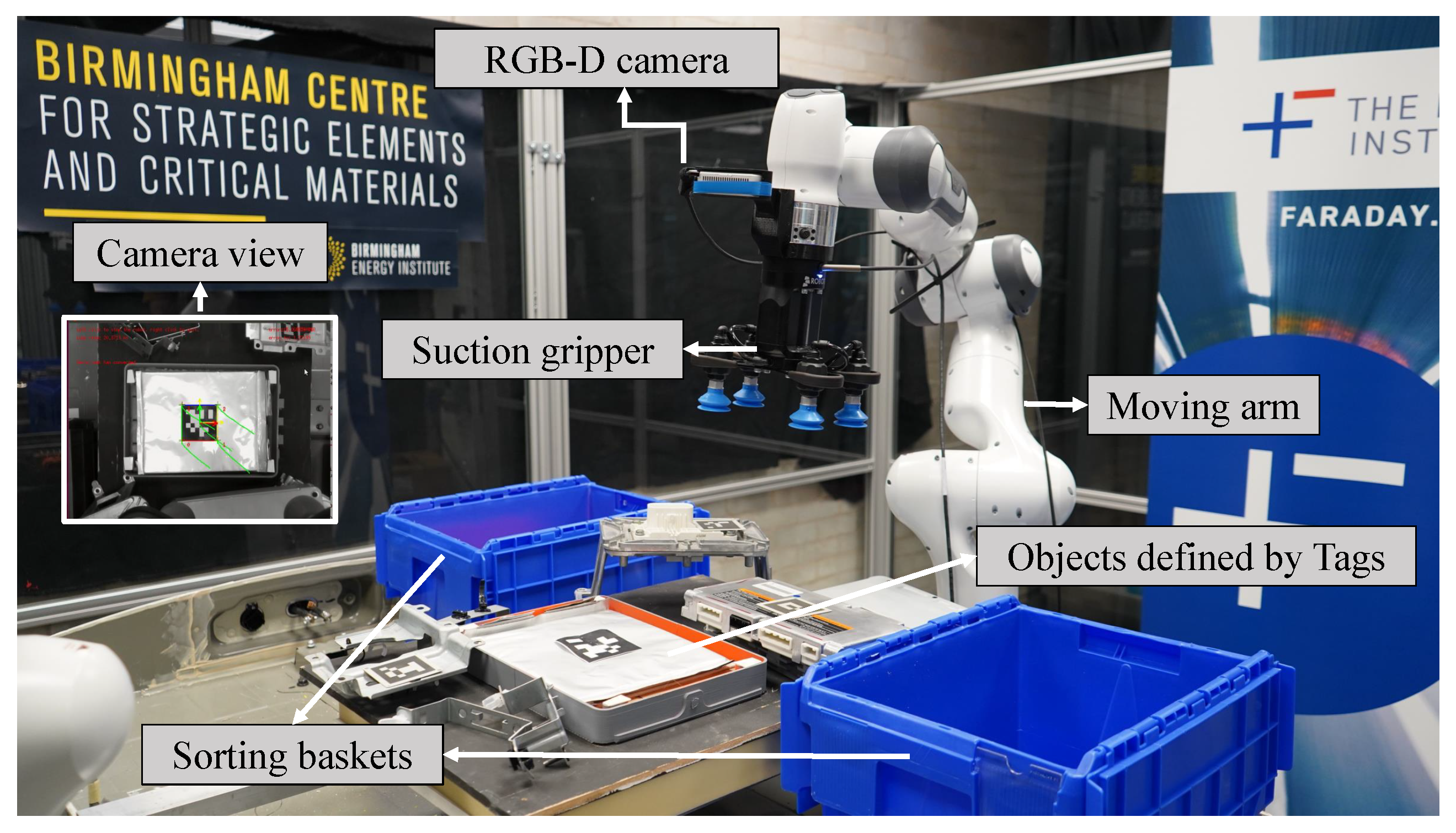
3.2. Design of Setup 2

The second setup was designed to evaluate the efficacy of the proposed DHVS method for sorting application. Figure 1 depicts the experimental setup used for sorting the dismantled components of an EV battery pack (Nissan Leaf 20212). The VS has been used to guide the suction gripper towards the battery module (i.e., the object with an attached marker). Then, the battery module will be lifted and will be placed in the corresponding basket. The rationale for performing this case study is that in industry, the robot and the object that the robot is interacting with must be precisely positioned, otherwise the robot might fail in completing the task due to uncertainties in the environment.

4. Results and Discussion

In this section, the behaviour of four different VS methods, in different case studies with various setups, are compared with each other.

4.1. Case Study 1: Singularity Analysis of VS Methods Using Setup 1

The performance of the robot in encountering singularities was analysed using four different VS techniques (Figure 5). As shown in Figure 5a, the position-based controller failed to track the desired features. This failure is caused by an error in 3D estimation of the target, created by the uncalibrated camera. Since DHVS compensates for two of six velocities directly from the image information, therefore the errors converge to zero (Figure 5d). This robustness is due to the fact that the image-based approaches do not require object pose estimation, therefore, it provides robust control in terms of calibration and regulating the errors. Not to mention that the overshoots in Figure 5d are caused by the uncalibrated camera parameters, but the key point is that the controller still managed to completethe task successfully.
As shown in Figure 5b, in IBVS the errors have not converged to zero because the controller generates a high velocity in the Z-axis, causing the robot to reach its joint limits. The main explanation for this restriction is that the controller is just considering the 2D information of the image. Consequently, the camera moves away from the target to compensate the rotation error about the Z-axis (camera retreat phenomenon). Nevertheless, in the DHVS method, the Z-axis errors and task space rotations are compensated by 3D calculation of the target. In Figure 5d, it is illustrated that the errors are successfully converged to zero by DHVS approach Figure 5d.
In the traditional HVS approach, the controller compensates for translation in Z-axis from the 2D information given by the camera. As a result, the controller continues to generate a non-optimized trajectory for the camera, which result in generating robot singularity. Figure 5c clearly shows that the controller using the HVS method failed to converge the errors to zero.
In summary, Figure 5 suggests that the proposed DHVS approach could avoid the singularity, mitigate the discontinuities, and complete the VS tasks without the use of complex and time-consuming methods (Figure 5d), while the other VS methods failed to complete the task successfully.

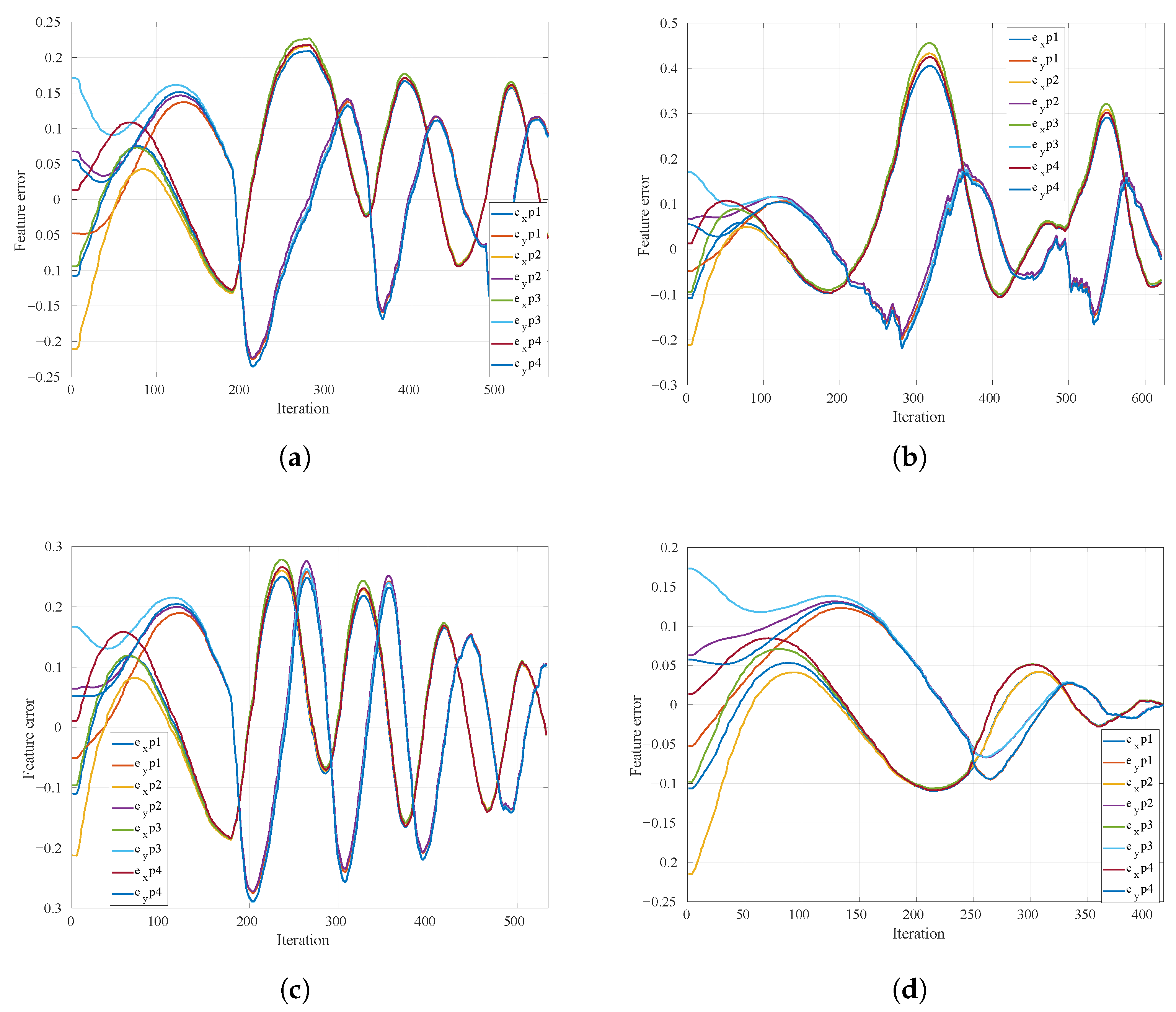
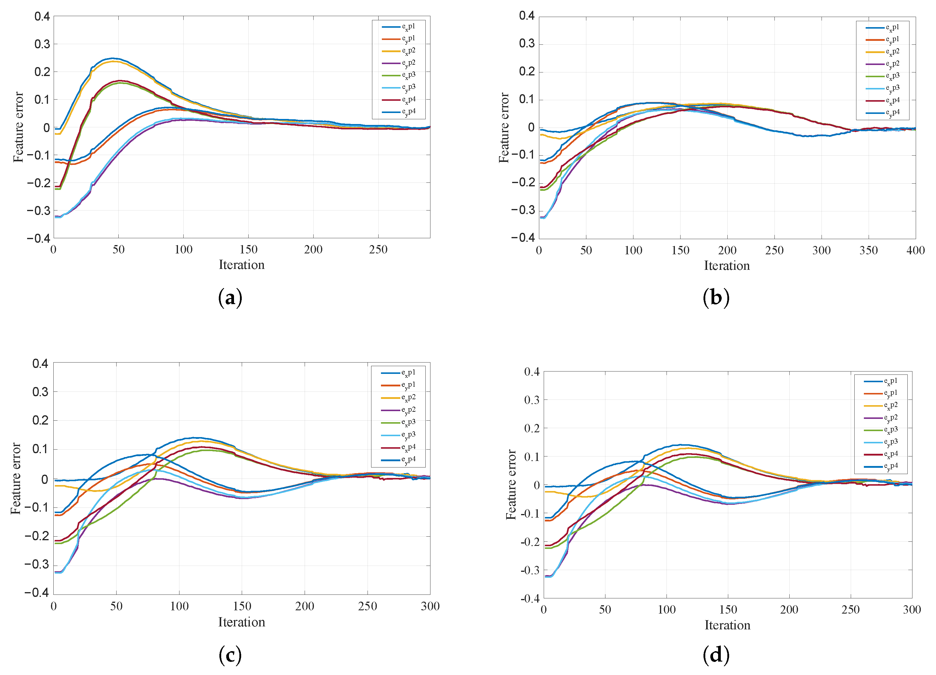
4.2. Case Study 2: Performance Analysis of Four VS Methods Using Setup 1

In this section, the effective parameters during tracking 10 positions by four different VS methods are compared with each other quantitatively and the results are tabulated in Table 1, Table 2 and Table 3.
According to Table 1, the DHVS method has a lower mean RMSE than PBVS and HVS, and the range of feature error in PBVS and the classical HVS is greater than that value in the DHVS. As a result, in the DHVS, the object is less likely to be missed from the camera screen than in the other two approaches. Not to mention that the DHVS method is quicker than traditional HVS, and needs fewer iterations to complete the same mission. Table 1 shows that the IBVS method not only has the smallest range of feature error, but also the smallest RMSE as compared to other approaches.
Without a doubt, IBVS performs better in the image-plane if there is no singularity or local minima. However, the controller operates blindly in the Cartesian space (with the highest RMSE for location and orientation as shown in Table 2). Large camera motions are common in the IBVS approach. As shown in Table 2, in Cartesian space, the DHVS method performed better than IBVS and HVS, as one would expect. However, the mean RMSE amounts of position and orientation in the PBVS method were less than their counterparts in the other three methods. As a consequence, in Cartesian space, the PBVS method had the best results, followed by DHVS.
Ultimately, the DHVS method indicates more optimised efficiency in the Cartesian space than IBVS and HVS (based on the amounts of mean RMSE shown in Table 2). Furthermore, DHVS outperforms PBVS and HVS in image-space (based on the amounts of RMSE and feature error ranges, shown in Table 1). In Table 3, a quantitative comparison of manipulability has been presented. When using the DHVS approach for VS, the mean of manipulability across the entire path is higher than when using the other three methods. The mean of manipulability with our proposed DHVS method after 10 different trials was 0.0484. However, for the same number of trials and the same initial position of the robot and the marker, this amount was 0.0407 for the IBVS method, 0.0446 for the PBVS method and 0.0396 for the classical hybrid method. In conclusion, the proposed DHVS technique clearly had advantages in terms of controllability and the ability to select a wider range of joint positions, compared to PBVS, IBVS and HVS approaches.
As a prime example, in Figure 6 and Figure 7, the behaviours of different VS methods for one of the experiments (i.e., tracking one of the ten positions) in have been depicted this case study.
According to Figure 6 and Figure 7, the proposed hybrid approach will not inherently have the best performance in tracking the features in the image-space and Cartesian space (robot space), but it will have an optimised performance in both.
It stems from the fact that translation in X-axis and Y-axis of the camera velocities are computed directly from the image space, while the rest are computed from 3D reconstruction of the environment. Furthermore, as compared to HVS and PBVS, the object in DHVS is less likely to be lost from the camera FOV. This conclusion was reached by comparing the maximum feature error in Figure 6d to the one in Figure 6a,c, which is less. The larger the error, the more likely the feature lost from the camera FOV.
According to Figure 7, DHVS (the blue path) has a shorter camera path than HVS (the purple path) and IBVS (the red path). To elaborate, the camera (or the robot EE) travelled 0.843 m distance in DHVS; however, this value is 0.942 m and 0.917 m in IBVS and HVS, respectively. In PBVS, the camera travelled distance is 0.722 m, which provides the most optimised Cartesian trajectory of the robot EE, as predicted.
The IBVS reflects the most optimised path in the camera frame as shown in Figure 6b, followed by DHVS method. IBVS has a lower RMSE than the other three VS approaches. In Figure 6, this amount is 0.036 in PBVS, 0.021 in IBVS, 0.032 in HVS and 0.028 in DHVS. As shown in Figure 6b, the maximum feature error along the entire path is 0.098, indicating that there is a very low chance of losing the object from the camera FOV. Since PBVS controller performs blindly in the image screen, it has the most undesirable RMSE (0.036) in the camera screen. As illustrated in Figure 6a, PBVS has the highest feature error (0.24) compared to other approaches, therefore it is more likely to lose the object from the camera FOV. Figure 6c,d show that the DHVS method is faster (converged in 300 iterations) than HVS method (converged within 443 iterations) and the RMSE amount is less in DHVS (less likely to lose the features).

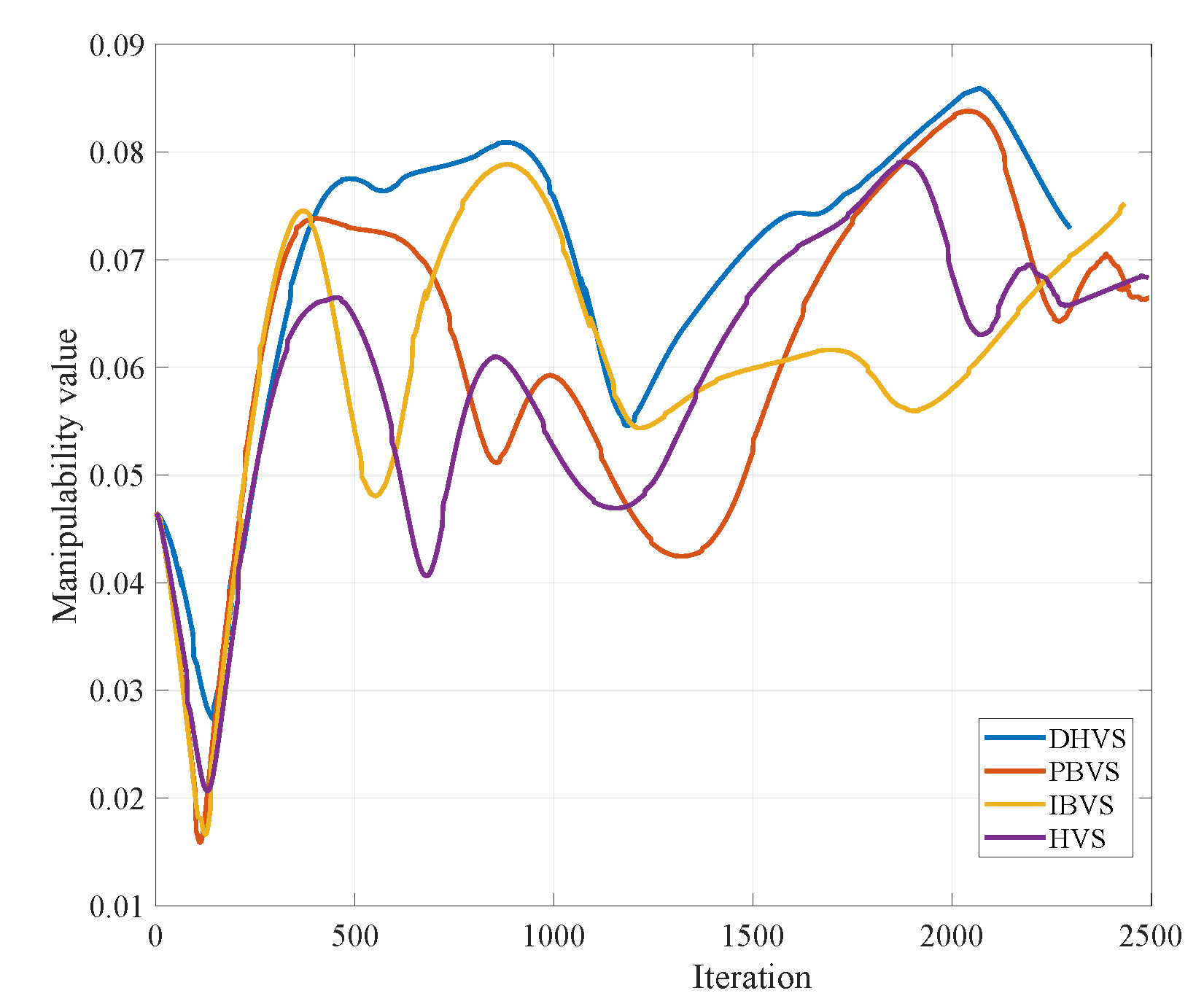
4.3. Case Study 3: Manipulability Analysis of Four VS Methods Using Setup 1

Four different visual servoing methods (DHVS, IBVS, HVS, PBVS) have been used to track the object. Figure 8 depicts the amount of manipulability for the VS methods. As shown in Figure 8, the manipulability of the DHVS method was mostly greater than the other three methods. The manipulability value at the time zero is the same since the robot started moving from the same position with an identical configuration during all trials. The minimum amount of manipulability for the DHVS method is 0.0681, while this amount is 0.0588 for IBVS, 0.0613 for PBVS and 0.0628 for the HVS method.
In Figure 9, the manipulability ellipsoid of the robot in its minimum amount (lowest amount of controllability for the robot) for different VS approaches has been illustrated. Since the manipulability ellipsoid is a hyper ellipsoid in six dimensions and plotting this in 3D space is a complex task, the first three elements of the ellipsoid have been plotted (i.e., translational velocities). From the plots in Figure 9, it is obvious that the proposed hybrid method has better controllability on the robot movements, compared to IBVS, PBVS, and HVS methods. The more isotropic the ellipsoid, the higher the controllability of the robot.

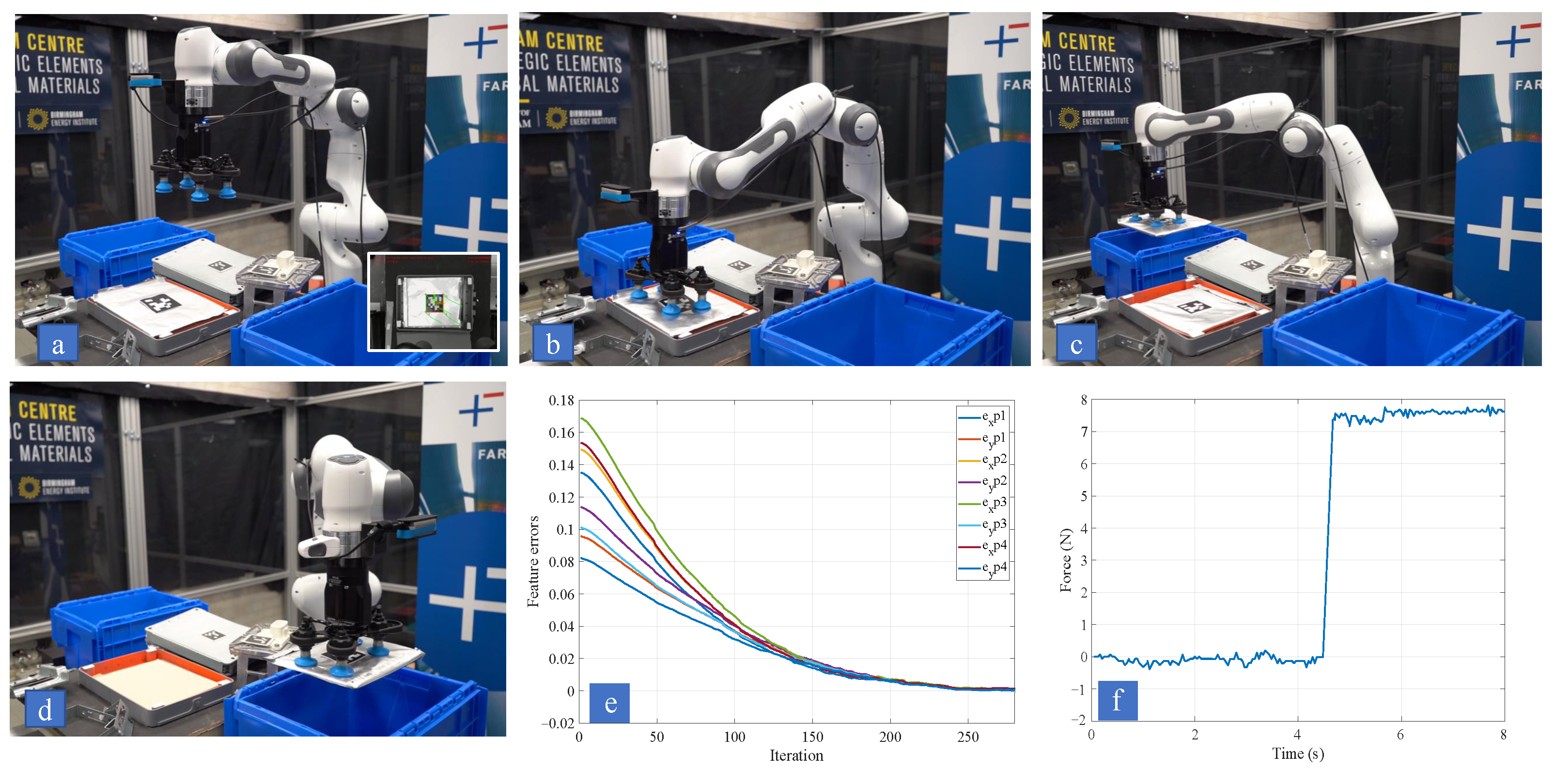
4.4. Sorting Dismantled EV Battery Components by DHVS Using Setup 2

Currently, the process of dismantling the EV battery packs carries out manually and robotic disassembly is limited to minor tasks with assistance of human [36]. The manual operations take time and require qualified workers to complete. As a result, manual disassembly is not economical [37]. A solution to this challenge is fully automating the dismantling process to reduce the cost and to increase the safety [38].
As a proof of concept, we designed the fourth case study to demonstrate the capability of the developed DHVS method in automating the process of sorting the dismantled EV battery components. This demonstration is carried out by using the Setup 2 that introduced in Section 3.2 (Figure 10). The manipulator arm tracks the object by converging the current features in the camera screen to the desired ones (red dots in Figure 10a). The trajectory of each feature is shown in green in the camera screen (Figure 10a). The convergence threshold for tracking is set to 0.00005 m. By using the transformation matrix which links the camera to the vacuum suction gripper, the robot moves to a position above the object. Then, the robot moves in −Z axis till makes contact with the object (Figure 10b,f). The external force is calculated using the Jacobian of the robot and the joint force sensors (Figure 10e). The next step is to lift the object using the vacuum suction gripper (Figure 10c), and place it in the desired basket, depending on whether they are reusable or should be discarded (Figure 10d).

5. Conclusions

In this study, a hybrid visual servoing approach was proposed, called Decoupled Hybrid Visual Servoing (DHVS). The proposed method was developed to address the drawbacks of the classical IBVS, PBVS and HVS approaches, and to improve their performances. In the DHVS method, three rotations and translations along the Z-axis have been decoupled from the image-Jacobian and controlled by 3D reconstruction of visual features. Instead of using a constant gain, adaptive gains were used to reduce the convergence time. The damped least square approach was used to smooth out the discontinuities and reduce the effect of robot singularities. In addition, image singularities generated by translation in the Z-axis, as well as rotations, are avoided in the proposed DHVS method. The reason is that the non-linear independent columns and rows, which cause the interaction matrix to lose rank, will be removed by decoupling the image Jacobian. It was found that the robot functionality increased during VS by defining manipulability as a secondary task, and solving redundancy resolution with the classical projection operator process. The proposed method not only has an optimised solution for the robot EE trajectory, but it also takes into account the image-space optimised trajectories of the features. Moreover, it is less likely to lose the object from the camera FOV in comparison with PBVS and HVS methods, and it is more robust to camera calibrations compared to PBVS. The proposed DHVS method has been compared with other VS methods in simulation and validated in the real worldSimulation and experimental results suggested that DHVS method has better performance in tracking the visual features in comparison with the other VS methods. In future study, Deep Neural Networks will be used to extract the features and to overcome the complexity of feature selection.

Author Contributions

Conceptualization, A.R., A.A. and R.S.; methodology, A.A.; software, A.A; validation, A.R. and A.A.; formal analysis, A.A.; investigation, A.R. and A.A.; resources, A.R., A.A. and R.S.; data curation, A.A.; writing—original draft preparation, A.R. and A.A.; writing—review and editing, A.R., A.A. and R.S.; visualization, A.A.; supervision, A.R. and R.S.; project administration, A.R.; funding acquisition, A.R and R.S. All authors have read and agreed to the published version of the manuscript.

Funding

This research was conducted as part of the project called “Reuse and Recycling of Lithium-Ion Batteries” (RELIB). This work was supported by the Faraday Institution [grant number FIRG005].

Institutional Review Board Statement

Not applicable.

Informed Consent Statement

Not applicable.

Data Availability Statement

The video that supports the findings of this study (Improving the manipulability of a redundant arm using Decoupled Hybrid Visual Servoing) is openly available in Figshare (https://figshare.com/articles/media/Improving_the_manipulability_of_a_redundant_arm_using_Decoupled_Hybrid_Visual_Servoing/17040620 (accessed on 23 November 2021)) with doi (10.6084/m9.figshare.17040620).

Conflicts of Interest

The authors declare that they have no conflict of interest.

References

  1. Servoing, V. Real Time Control of Robot Manipulators Based on Visual Sensory Feedback; World Scientific: Singapore, 1993. [Google Scholar]
  2. Mansard, N.; Chaumette, F. A new redundancy formalism for avoidance in visual servoing. In Proceedings of the 2005 IEEE/RSJ International Conference on Intelligent Robots and Systems, Edmonton, AB, Canada, 2–6 August 2005; IEEE: Piscataway, NJ, USA, 2005; pp. 468–474. [Google Scholar]
  3. Chaumette, F.; Hutchinson, S.; Corke, P. Visual servoing. In Springer Handbook of Robotics; Springer: Berlin/Heidelberg, Germany, 2016; pp. 841–866. [Google Scholar]
  4. Rastegarpanah, A.; Ahmeid, M.; Marturi, N.; Attidekou, P.S.; Musbahu, M.; Ner, R.; Lambert, S.; Stolkin, R. Towards robotizing the processes of testing lithium-ion batteries. Proc. Inst. Mech. Eng. Part I J. Syst. Control Eng. 2021, 235, 1309–1325. [Google Scholar] [CrossRef]
  5. Vicentini, F.; Pedrocchi, N.; Beschi, M.; Giussani, M.; Iannacci, N.; Magnoni, P.; Pellegrinelli, S.; Roveda, L.; Villagrossi, E.; Askarpour, M.; et al. PIROS: Cooperative, safe and reconfigurable robotic companion for CNC pallets load/unload stations. In Bringing Innovative Robotic Technologies from Research Labs to Industrial End-Users; Springer: Berlin/Heidelberg, Germany, 2020; pp. 57–96. [Google Scholar]
  6. Rastegarpanah, A.; Aflakian, A.; Stolkin, R. Optimized hybrid decoupled visual servoing with supervised learning. Proc. Inst. Mech. Eng. Part I J. Syst. Control. Eng. 2021. [Google Scholar] [CrossRef]
  7. Paolillo, A.; Chappellet, K.; Bolotnikova, A.; Kheddar, A. Interlinked visual tracking and robotic manipulation of articulated objects. IEEE Robot. Autom. Lett. 2018, 3, 2746–2753. [Google Scholar] [CrossRef] [Green Version]
  8. Roveda, L.; Castaman, N.; Ghidoni, S.; Franceschi, P.; Boscolo, N.; Pagello, E.; Pedrocchi, N. Human-robot cooperative interaction control for the installation of heavy and bulky components. In Proceedings of the 2018 IEEE International Conference on Systems, Man, and Cybernetics (SMC), Miyazaki, Japan, 7–10 October 2018; IEEE: Piscataway, NJ, USA, 2018; pp. 339–344. [Google Scholar]
  9. Francois, C.; Hutchinson, S. Visual servo control Part I: Basic approaches. IEEE Robot. Autom. Mag. 2006, 13, 82–90. [Google Scholar]
  10. Deng, L.; Janabi-Sharifi, F.; Wilson, W.J. Stability and robustness of visual servoing methods. In Proceedings of the 2002 IEEE International Conference on Robotics and Automation (Cat. No. 02CH37292), Washington, DC, USA, 11–15 May 2002; IEEE: Piscataway, NJ, USA, 2002; Volume 2, pp. 1604–1609. [Google Scholar]
  11. Han, X.F.; Laga, H.; Bennamoun, M. Image-based 3D Object Reconstruction: State-of-the-Art and Trends in the Deep Learning Era. arXiv 2019, arXiv:1906.06543. [Google Scholar] [CrossRef] [PubMed] [Green Version]
  12. Chaumette, F. Potential problems of stability and convergence in image-based and position-based visual servoing. In The Confluence of Vision and Control; Springer: Berlin/Heidelberg, Germany, 1998; pp. 66–78. [Google Scholar]
  13. Corke, P.I.; Hutchinson, S.A. A new partitioned approach to image-based visual servo control. IEEE Trans. Robot. Autom. 2001, 17, 507–515. [Google Scholar] [CrossRef] [Green Version]
  14. Palmieri, G.; Palpacelli, M.; Battistelli, M.; Callegari, M. A comparison between position-based and image-based dynamic visual servoings in the control of a translating parallel manipulator. J. Robot. 2012, 2012, 103954. [Google Scholar] [CrossRef] [Green Version]
  15. Wang, H. Towards manipulability of interactive Lagrangian systems. Automatica 2020, 119, 108913. [Google Scholar] [CrossRef]
  16. Corke, P. Robotics, Vision and Control: Fundamental Algorithms in MATLAB® Second, Completely Revised; Springer: Berlin/Heidelberg, Germany, 2017; Volume 118. [Google Scholar]
  17. Gans, N.R.; Hutchinson, S.A. Stable visual servoing through hybrid switched-system control. IEEE Trans. Robot. 2007, 23, 530–540. [Google Scholar] [CrossRef]
  18. Kumar, D.S.; Jawahar, C. Robust homography-based control for camera positioning in piecewise planar environments. In Computer Vision, Graphics and Image Processing; Springer: Berlin/Heidelberg, Germany, 2006; pp. 906–918. [Google Scholar]
  19. Chesi, G.; Hashimoto, K.; Prattichizzo, D.; Vicino, A. Keeping features in the field of view in eye-in-hand visual servoing: A switching approach. IEEE Trans. Robot. 2004, 20, 908–914. [Google Scholar] [CrossRef]
  20. Cervera, E.; Del Pobil, A.P.; Berry, F.; Martinet, P. Improving image-based visual servoing with three-dimensional features. Int. J. Robot. Res. 2003, 22, 821–839. [Google Scholar] [CrossRef]
  21. Malis, E.; Chaumette, F.; Boudet, S. 2 1/2 D visual servoing. IEEE Trans. Robot. Autom. 1999, 15, 238–250. [Google Scholar] [CrossRef] [Green Version]
  22. Hu, G.; Gans, N.; Dixon, W. Quaternion-based visual servo control in the presence of camera calibration error. Int. J. Robust Nonlinear Control IFAC-Affil. J. 2010, 20, 489–503. [Google Scholar] [CrossRef]
  23. Marey, M.; Chaumette, F. A new large projection operator for the redundancy framework. In Proceedings of the 2010 IEEE International Conference on Robotics and Automation, Anchorage, AK, USA, 3–7 May 2010; IEEE: Piscataway, NJ, USA, 2010; pp. 3727–3732. [Google Scholar]
  24. Mansard, N.; Chaumette, F. Directional redundancy for robot control. IEEE Trans. Autom. Control 2009, 54, 1179–1192. [Google Scholar] [CrossRef] [Green Version]
  25. Yoshikawa, T. Basic optimization methods of redundant manipulators. Lab. Robot. Autom. 1996, 8, 49–60. [Google Scholar] [CrossRef]
  26. Chaumette, F.; Marchand, É. A redundancy-based iterative approach for avoiding joint limits: Application to visual servoing. IEEE Trans. Robot. Autom. 2001, 17, 719–730. [Google Scholar] [CrossRef] [Green Version]
  27. Nelson, B.J.; Khosla, P.K. Strategies for increasing the tracking region of an eye-in-hand system by singularity and joint limit avoidance. Int. J. Robot. Res. 1995, 14, 255–269. [Google Scholar] [CrossRef]
  28. Liegeois, A. Automatic supervisory control of the configuration and behavior of multibody mechanisms. IEEE Trans. Syst. Man Cybern. 1977, 7, 868–871. [Google Scholar]
  29. Hu, G.; Gans, N.R.; Dixon, W.E. Adaptive Visual Servo Control; Springer: New York, NY, USA, 2009. [Google Scholar]
  30. Kermorgant, O.; Chaumette, F. Dealing with constraints in sensor-based robot control. IEEE Trans. Robot. 2013, 30, 244–257. [Google Scholar] [CrossRef] [Green Version]
  31. Spong, M. Hutchinso, n. Seth, and MV Vidyasagar, “Robot Modeling and Control”; John Wiley& Sons: Hoboken, NJ, USA, 2006. [Google Scholar]
  32. Baerlocher, P.; Boulic, R. Task-priority formulations for the kinematic control of highly redundant articulated structures. In Proceedings of the 1998 IEEE/RSJ International Conference on Intelligent Robots and Systems. Innovations in Theory, Practice and Applications (Cat. No. 98CH36190), Victoria, BC, Canada, 17 October 1998; IEEE: Piscataway, NJ, USA, 1998; Volume 1, pp. 323–329. [Google Scholar]
  33. Maciejewski, A.A.; Klein, C.A. Numerical filtering for the operation of robotic manipulators through kinematically singular configurations. J. Robot. Syst. 1988, 5, 527–552. [Google Scholar] [CrossRef]
  34. Fruchard, M.; Morin, P.; Samson, C. A framework for the control of nonholonomic mobile manipulators. Int. J. Robot. Res. 2006, 25, 745–780. [Google Scholar] [CrossRef]
  35. Vahrenkamp, N.; Asfour, T.; Metta, G.; Sandini, G.; Dillmann, R. Manipulability analysis. In Proceedings of the 2012 12th IEEE-RAS International Conference on Humanoid Robots (Humanoids 2012), Osaka, Japan, 29 November–1 December 2012; IEEE: Piscataway, NJ, USA, 2012; pp. 568–573. [Google Scholar]
  36. Wegener, K.; Andrew, S.; Raatz, A.; Dröder, K.; Herrmann, C. Disassembly of electric vehicle batteries using the example of the Audi Q5 hybrid system. Procedia CIRP 2014, 23, 155–160. [Google Scholar] [CrossRef] [Green Version]
  37. Alfaro-Algaba, M.; Ramirez, F.J. Techno-economic and environmental disassembly planning of lithium-ion electric vehicle battery packs for remanufacturing. Resour. Conserv. Recycl. 2020, 154, 104461. [Google Scholar] [CrossRef]
  38. Pistoia, G.; Liaw, B. Behaviour of Lithium-Ion Batteries in Electric Vehicles: Battery Health, Performance, Safety, and Cost; Springer: Berlin/Heidelberg, Germany, 2018. [Google Scholar]
Figure 1. The automated process of sorting the dismantled EV battery components. The object tracking is carried out by the proposed VS method (DHVS) and the object is manipulated using a redundant manipulator arm.
Applsci 11 11566 g001
Figure 2. Schematic diagram of problem domains in visual servoing. The proposed DHVS method reduces the image and robot singularity configurations, and keeps the robot away from the joint limits. In addition, it is less likely to lose the object from the camera FOV, and it is more robust to the camera calibrations than PBVS method (It generates controllable trajectories with a higher amount of robot Jacobian, resulting in better manipulability).
Applsci 11 11566 g002
Figure 3. The control schema of the proposed visual servoing approach (DHVS).
Applsci 11 11566 g003
Figure 4. The modelled setup 1 in (a) the simulation hlenvironment, and (b) the real world.
Applsci 11 11566 g004
Figure 5. Performance analysis of four different VS methods in completing a similar task in presence of singularity. (a) Failure in completing the VS task with PBVS approach. (b) Failure in completing the VS task with IBVS approach. (c) Failure in completing the VS task with HVS approach. (d) Success in completing the VS task with DHVS approach.
Applsci 11 11566 g005
Figure 6. The real world result of the feature errors in different methods for the same scenario. (a) Feature errors in PBVS approach. (b) Feature errors in IBVS approach. (c) Feature errors in HVS approach. (d) Feature errors in DHVS approach.
Applsci 11 11566 g006
Figure 7. The real world camera (EE) trajectory in different methods for the same scenario in Figure 6.
Applsci 11 11566 g007
Figure 8. Analysing the manipulability of different VS methods during tracking the trajectory (introduced in Case study 3) of a dynamic object.
Applsci 11 11566 g008
Figure 9. Manipulability ellipsoid in its minimum amount for three translation degrees of freedom in different VS approaches. (a) The manipulability ellipsoid of the robot in its minimum value with the PBVS approach. (b) The manipulability ellipsoid of the robot in its minimum value with the IBVS approach. (c) The manipulability ellipsoid of the robot in its minimum value with the HVS approach. (d) The manipulability ellipsoid of the robot in its minimum value with DHVS approach.
Applsci 11 11566 g009
Figure 10. DHVS method is used for tracking the visual features attached to a Lithium-ion battery. Manipulability is considered as a secondary task for the controller. By using the proposed DHVS, the robot arm performs the task of sorting the battery; (a) the robot will follow the visual features of the object online; the tracked path of each feature is shown in the camera screen. (b) The robot goes down straight to detect the surface by the force feedback. (c,d) The object has been lifted by the vacuum suction gripper, and then released the battery in the corresponding basket. (e) The feature errors converged to zero during Visual Servoing. (f) The force value in the Z-axis for detecting the object surface.
Applsci 11 11566 g010
Table 1. Performance of visual servoing methods in the image space.
MethodRMSEFeature Error
Range
IterationMean of ErrorMean Standard
Deviation of Error
IBVS0.0222[−0.36, 0.310]4530.01520.0095
PBVS0.0383[−0.445, 0.507]4870.02040.0164
HVS0.0273[−0.448, 0.486]6240.01680.0141
DHVS0.0258[−0.439, 0.443]5870.01590.0112
Table 2. Performance of visual servoing methods in the Cartesian space.
MethodRMSE of
Position (m)
RMSE of
Orientation ( )
Camera (or EE)
Travelled Distance (m)
IBVS0.0369.430.942
PBVS0.0226.540.722
HVS0.0348.410.917
DHVS0.0316.890.834
Table 3. Comparison of manipulability in different VS methods.
MethodRMSEManipulability
Mean
Manipulability
Range
Iteration
IBVS0.02220.0407[0.0140, 0.0810]153
PBVS0.03830.0446[0.0245, 0.0807]187
Hybrid VS0.02730.0396[0.0208, 0.0806]224
DHVS0.02490.0484[0.0289, 0.0810]205
Publisher’s Note: MDPI stays neutral with regard to jurisdictional claims in published maps and institutional affiliations.

