
Configuration of Non-Pumping Reactive Wells Considering Minimum Well Spacing


Abstract
:1. Introduction
2. Materials and Methods
2.1. Configurations of NPRW
2.2. Modeling Groundwater Flow and Contaminant Transport
2.3. Case Study: Contaminant Removal Using Various Configurations of NPRWs
2.4. Analysis of Removal Efficiency
3. Results and Discussion
3.1. Practical Configuration of NPRW
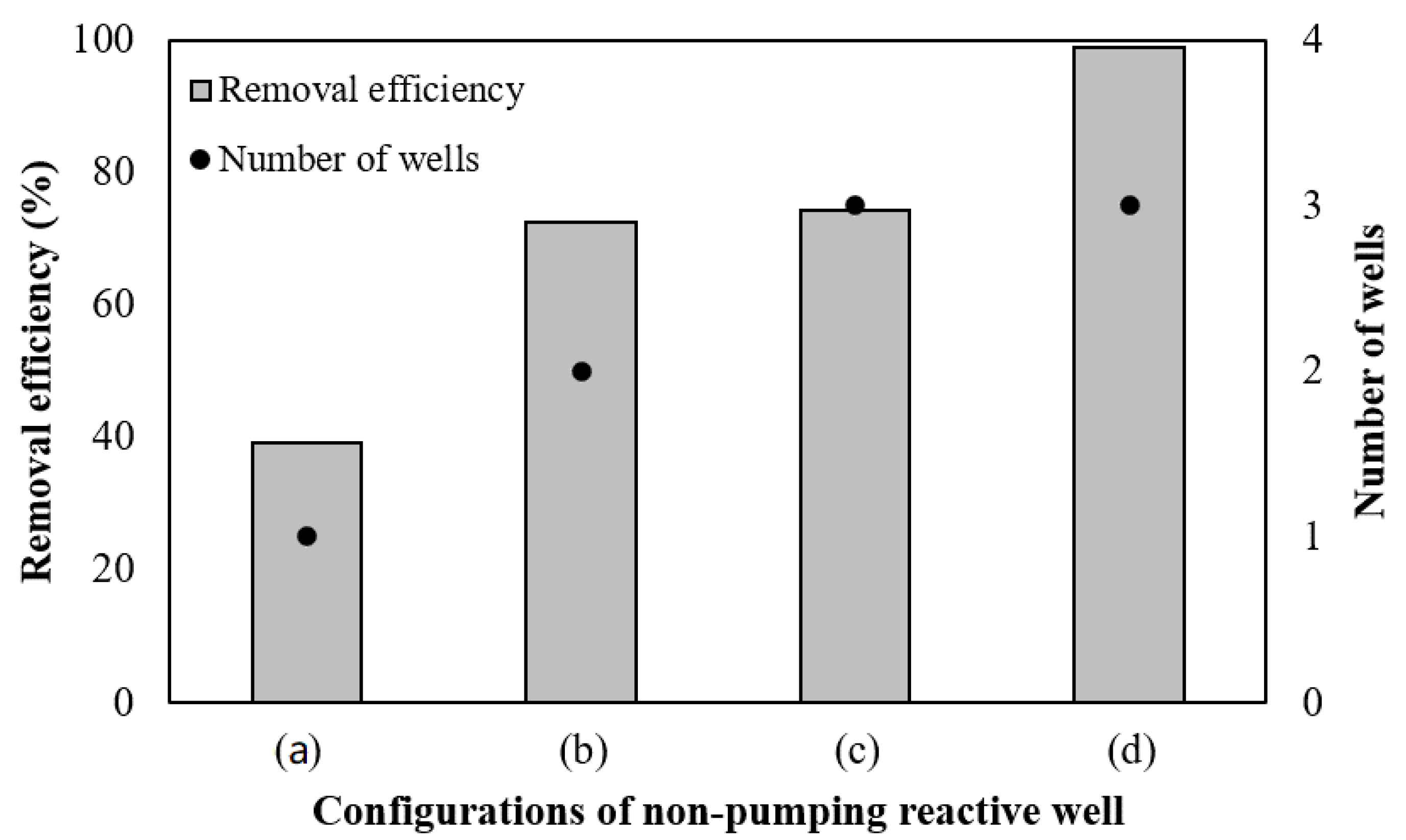
3.1.1. Removal of Contaminant Plume by Single NPRW
3.1.2. Configurations of NPRW Considering Field Constraints
3.1.3. Process to Design NPRW Considering Field Constraints
- (1)
- Determine the well diameter (d1) that can be applied to the well construction site.
- (2)
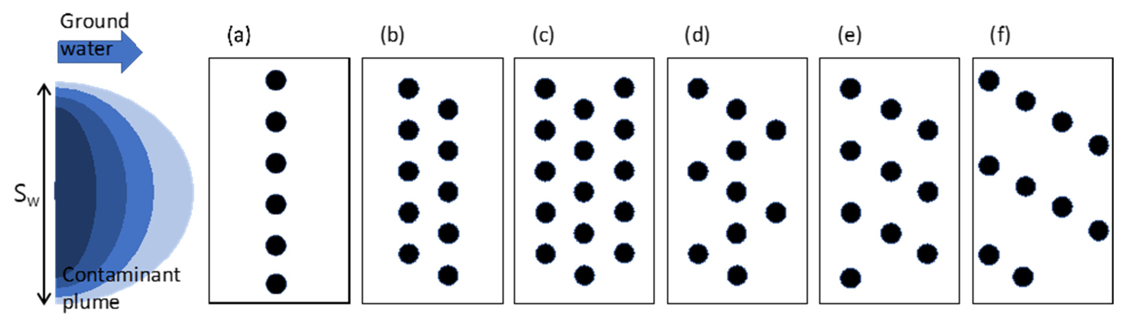
- Determine an imaginary pollution barrier line perpendicular to the direction of groundwater flow and longer than the width of the contaminant plume, Sw.
- (3)
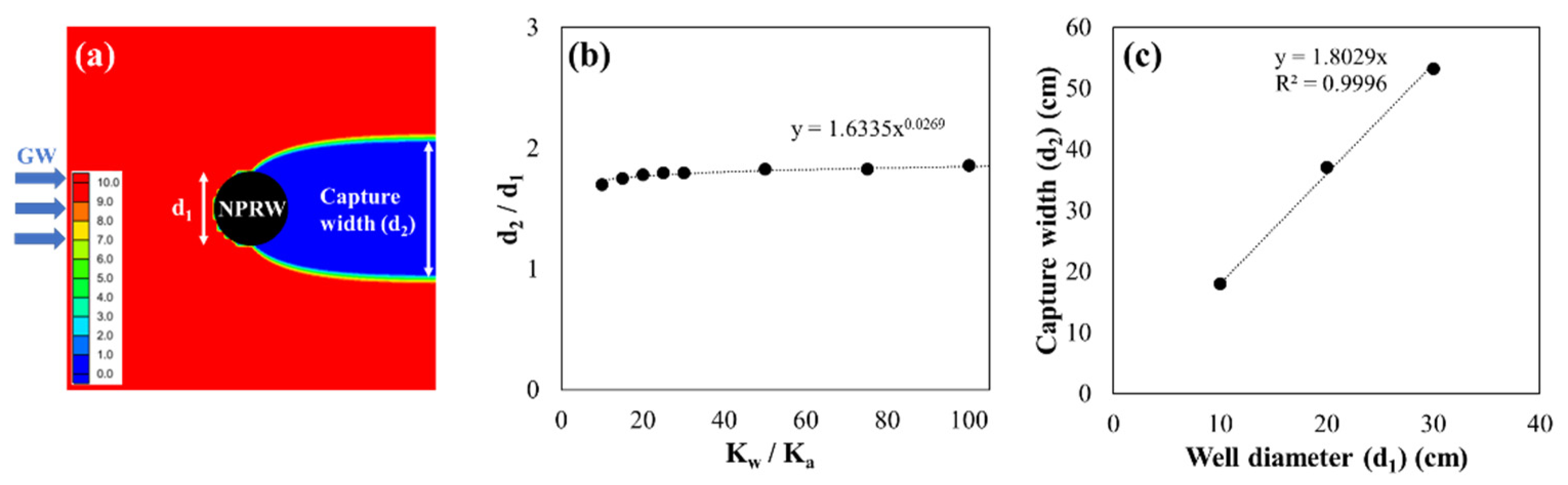
- Predict the capture width (d2) of a single well by considering the well diameter (d1) and the hydraulic conductivity of the reactive media and the geologic media. Previous studies reported that a highly permeable single well could capture contaminated groundwater flowing through a width 1.8–2.0 times greater than the well diameter [28,30]. The plume width captured by a single well (d2) is:where α is the groundwater capture efficiency of a well, which is defined as the ratio of the capture width to the diameter of a single well, d1.
- (4)
- Place the reactive wells along the contamination blocking line, spaced at a distance of d2.
- (5)
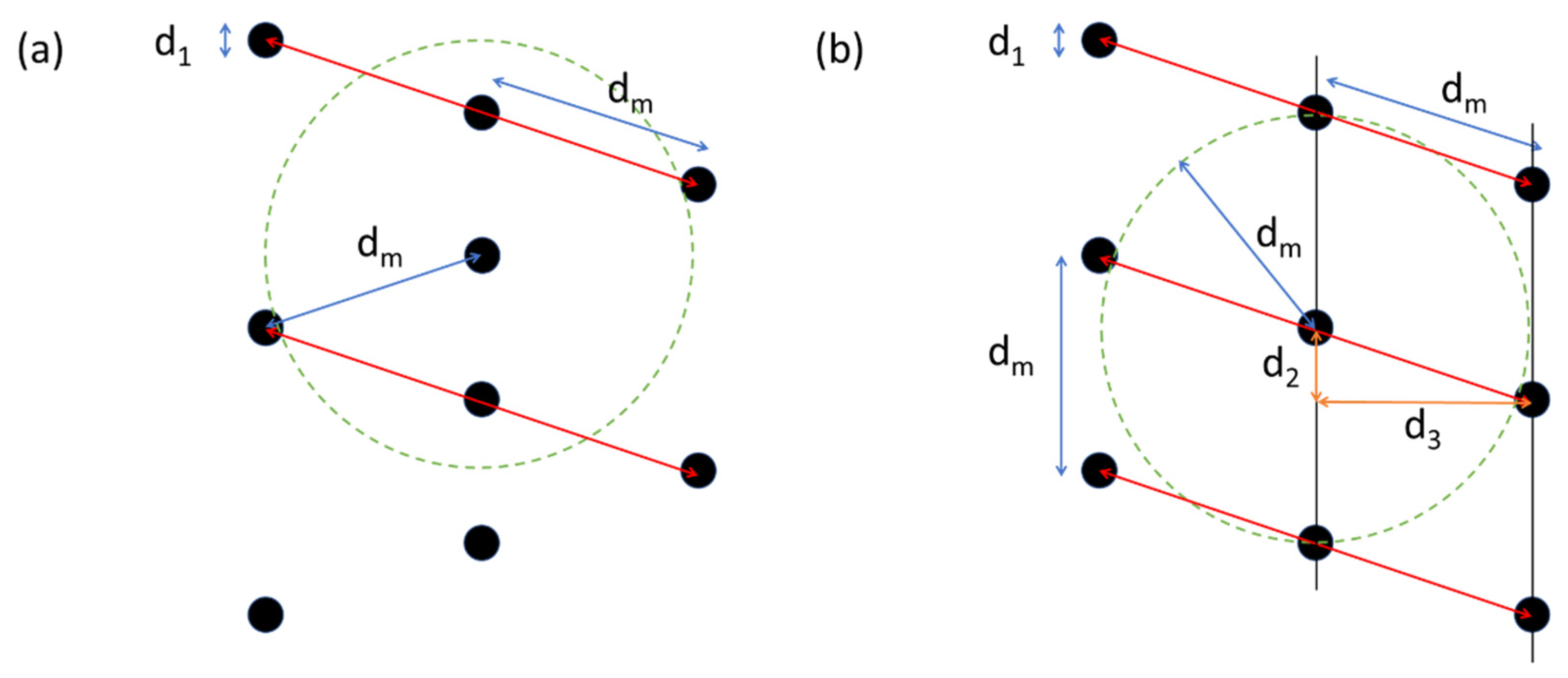
- In the case where d2 is closer than the minimum well space dm, the unit well segment (for example, the red lines in Figure 3b) is defined so that the width of the unit segment, Si, is greater than dm.where N is the number of wells in the unit segment (integer).
- (6)
- Optimize the configuration of the unit segment considering the site conditions, including the minimum well spacing. For example, some of the wells included in the unit segment may be moved in the downstream direction, thereby satisfying the limiting condition for minimum well spacing. Then, if a new well is installed in a place separated from the wells in the preceding transect by distance d2 and d3, in the transverse and longitudinal directions, respectively, the limiting condition of minimum well spacing can be satisfied. Here, d3 is the minimum distance between the transects, and it can be calculated by
- (7)
- The number of segments is determined as Ns (integer), using the ratio of the width of the contaminant plume, Sw, to the width of the unit segment, Si. The arrangement of NPRW should be wider than the width of the contaminant plume (Sw) to prevent contaminants from spreading downgradient. To prevent the spread of contaminants completely, the following condition should be satisfied:
- (8)
- The designed PRB system can be completed by arranging Ns unit segments along the pollution barrier line.
3.1.4. Sawtooth Array for Multiple Transect Configurations of NPRWs
3.2. Modeling Contaminant Transport through NPRWs
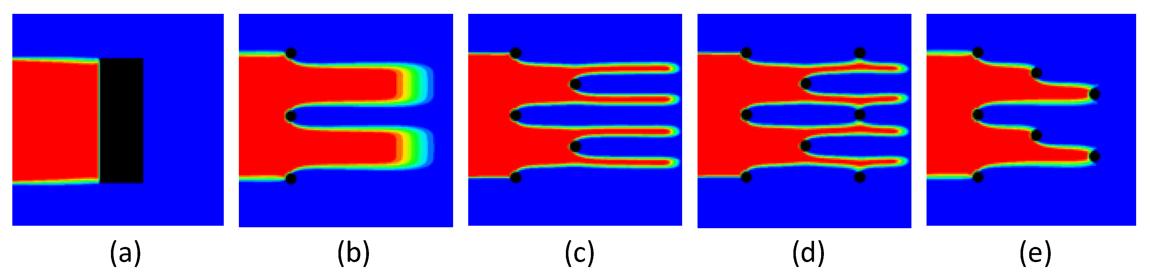
3.2.1. Prevention of Contaminant Spread by NPRW
3.2.2. Evaluation of NPRW Performance
3.3. Prediction of the Contaminant Removal Using Multiple Transect NPRW
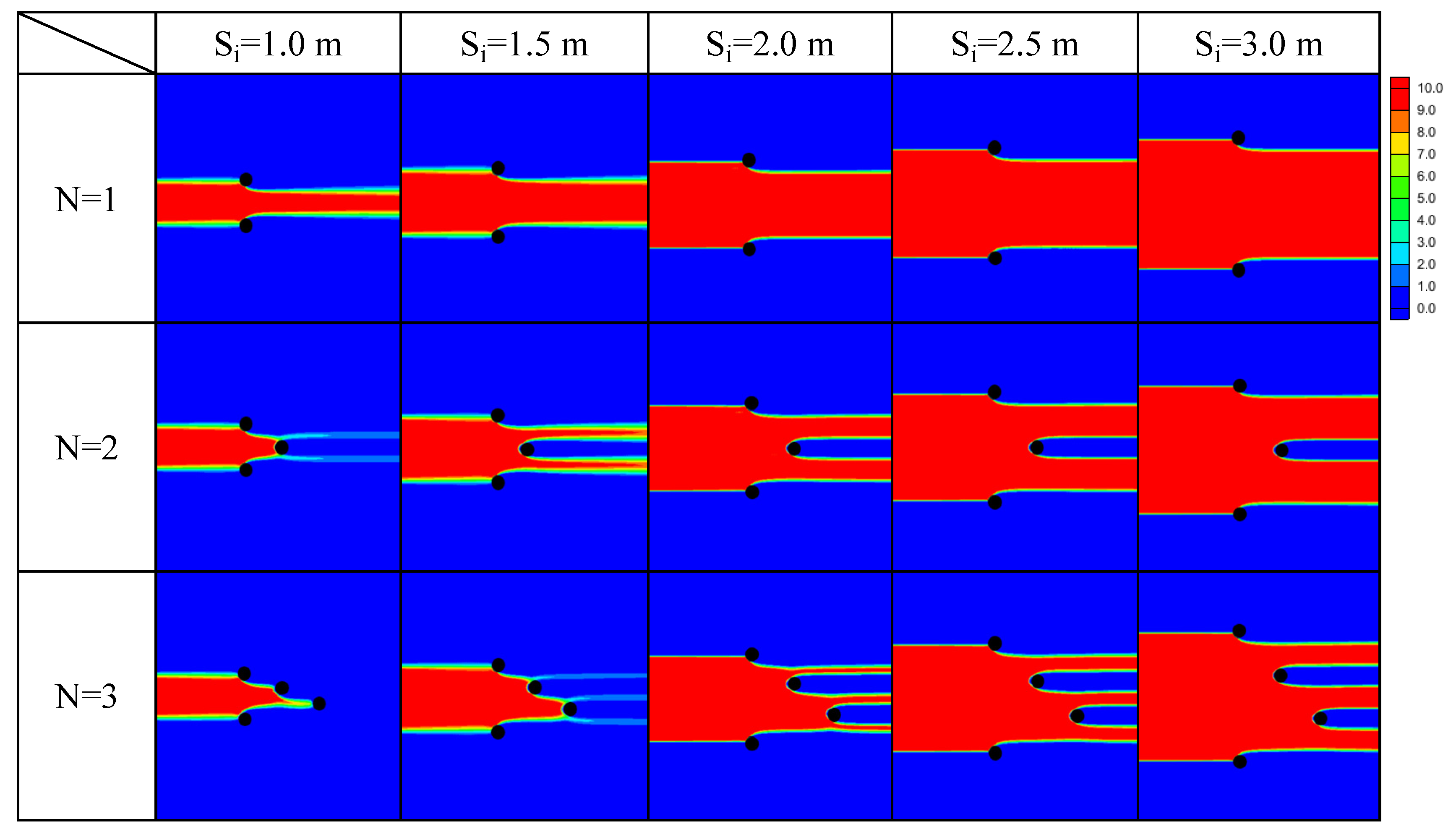
3.3.1. Performance Curve of Multiple Transect NPRW
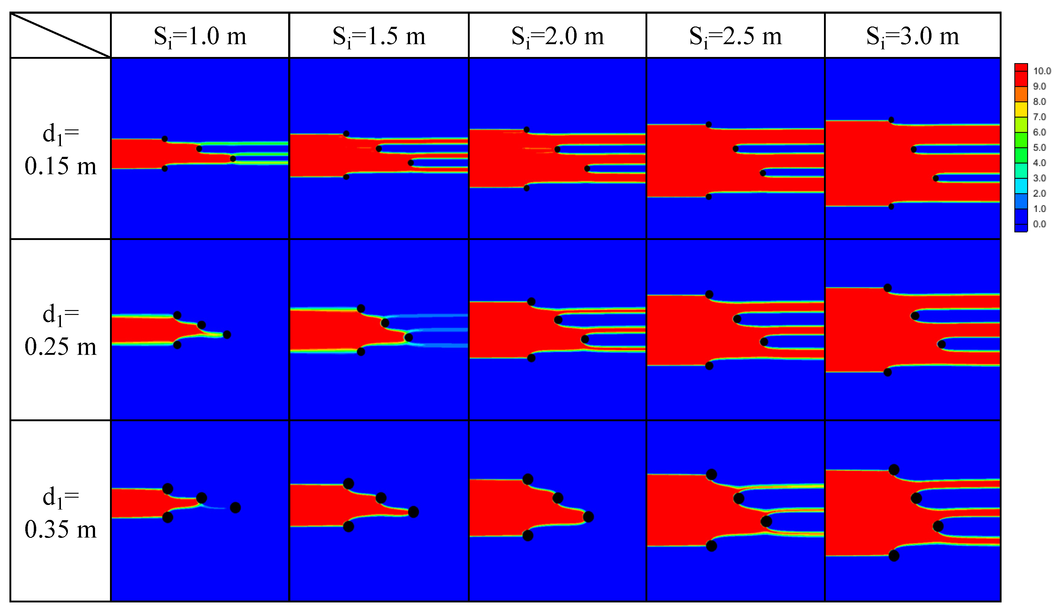
3.3.2. Effect of Minimum Well Spacing and Well Configurations on PRB Performance
3.4. Design of Practical Configurations of NPRW Based on the Performance Curves
4. Conclusions
Author Contributions
Funding
Institutional Review Board Statement
Informed Consent Statement
Data Availability Statement
Acknowledgments
Conflicts of Interest
References
- Price, S.J.; Ford, J.R.; Cooper, A.H.; Neal, C. Humans as major geological and geomorphological agents in the Anthropocene: The significance of artificial ground in Great Britain. Philosl. Trans. R. Soc. A 2011, 369, 1056–1084. [Google Scholar] [CrossRef] [PubMed]
- Fetter, C. Applied Hydrogeology, 4th ed.; Prentice-Hall: Upper Saddle River, NJ, USA, 2001; 598p. [Google Scholar]
- Singhal, B.B.S.; Gupta, R.P. Applied Hydrogeology of Fractured Rocks; Springer Science & Business Media: Berlin, Germany, 2010. [Google Scholar]
- Younger, P.L. Groundwater in the Environment: An introduction; John Wiley & Sons: Hoboken, NJ, USA, 2009. [Google Scholar]
- Powell, R.M.; Powell, P.D.; Puls, R.W. Economic Analysis of the Implementation of Permeable Reactive Barriers for Remediation of Contaminated Ground Water; U.S. Environmental Protection Agency: Washington, DC, USA, 2002.
- Hashim, M.A.; Mukhopadhyay, S.; Sahu, J.N.; Sengupta, B. Remediation technologies for heavy metal contaminated groundwater. J. Environ. Manag. 2011, 92, 2355–2388. [Google Scholar] [CrossRef] [PubMed]
- Ludwig, R.D.; McGregor, R.G.; Blowes, D.W.; Benner, S.G.; Mountjoy, K. A permeable reactive barrier for treatment of heavy metals. Ground Water 2002, 40, 59–66. [Google Scholar] [CrossRef] [PubMed]
- Woinarski, A.Z.; Stevens, G.W.; Snape, I. A natural zeolite permeable reactive barrier to treat heavy-metal contaminated waters in Antarctica—Kinetic and fixed-bed studies. Process. Saf. Environ. Prot. 2006, 84, 109–116. [Google Scholar] [CrossRef]
- Grau-Martinez, A.; Torrento, C.; Carrey, R.; Soler, A.; Otero, N. Isotopic evidence of nitrate degradation by a zero-valent iron permeable reactive barrier: Batch experiments and a field scale study. J. Hydrol. 2019, 570, 69–79. [Google Scholar] [CrossRef]
- Robertson, W.D.; Blowes, D.W.; Ptacek, C.J.; Cherry, J.A. Long-term performance of in situ reactive barriers for nitrate remediation. Ground Water 2000, 38, 689–695. [Google Scholar] [CrossRef]
- Robertson, W.D.; Vogan, J.L.; Lombardo, P.S. Nitrate removal rates in a 15-year-old permeable reactive barrier treating septic system nitrate. Ground Water Monit. R. 2008, 28, 65–72. [Google Scholar] [CrossRef]
- Stewart, D.I.; Csovari, M.; Barton, C.S.; Morris, K.; Bryant, D.E. Performance of a functionalised polymer-coated silica at treating uranium contaminated groundwater from a Hungarian mine site. Eng. Geol. 2006, 85, 174–183. [Google Scholar] [CrossRef]
- Guerin, T.F.; Horner, S.; McGovern, T.; Davey, B. An application of permeable reactive barrier technology to petroleum hydrocarbon contaminated groundwater. Water Res. 2002, 36, 15–24. [Google Scholar] [CrossRef]
- McGovern, T.; Guerin, T.F.; Horner, S.; Davey, B. Design, construction and operation of a funnel and gate in-situ permeable reactive barrier for remediation of petroleum hydrocarbons in groundwater. Water Air Soil Poll 2002, 136, 11–31. [Google Scholar] [CrossRef]
- Smith, C.C.; Anderson, W.F.; Freewood, R.J. Evaluation of shredded tyre chips as sorption media for passive treatment walls. Eng. Geol. 2001, 60, 253–261. [Google Scholar] [CrossRef]
- Bekele, D.N.; Du, J.H.; de Freitas, L.G.; Mallavarapu, M.; Chadalavada, S.; Naidu, R. Actively facilitated permeable reactive barrier for remediation of TCE from a low permeability aquifer: Field application. J. Hydrol. 2019, 572, 592–602. [Google Scholar] [CrossRef]
- Lai, K.C.K.; Lo, I.M.C.; Birkelund, V.; Kjeldsen, P. Field monitoring of a permeable reactive barrier for removal of chlorinated organics. J. Environ. Eng. 2006, 132, 199–210. [Google Scholar] [CrossRef]
- Vogan, J.L.; Focht, R.M.; Clark, D.K.; Graham, S.L. Performance evaluation of a permeable reactive barrier for remediation of dissolved chlorinated solvents in groundwater. J. Hazard. Mater. 1999, 68, 97–108. [Google Scholar] [CrossRef]
- Hosseini, S.M.; Ataie-Ashtiani, B.; Kholghi, M. Bench-Scaled Nano-Fe0 Permeable Reactive Barrier for Nitrate Removal. Ground Water Monit. Remediat. 2011, 31, 82–94. [Google Scholar] [CrossRef]
- Xu, J.; Wang, Y.; Weng, C.; Bai, W.L.; Jiao, Y.; Kaegi, R.; Lowry, G.V. Reactivity, Selectivity, and Long-Term Performance of Sulfidized Nanoscale Zerovalent Iron with Different Properties. Environ. Sci. Technol. 2019, 53, 5936–5945. [Google Scholar] [CrossRef]
- Vignola, R.; Bagatin, R.; D’Auris, A.D.F.; Flego, C.; Nalli, M.; Ghisletti, D.; Millini, R.; Sisto, R. Zeolites in a permeable reactive barrier (PRB): One year of field experience in a refinery groundwater—Part 1: The performances. Chem. Eng. J. 2011, 178, 204–209. [Google Scholar] [CrossRef]
- Wang, J.; Hou, L.A.; Yao, Z.K.; Jiang, Y.H.; Xi, B.D.; Ni, S.Y.; Zhang, L. Aminated electrospun nanofiber membrane as permeable reactive barrier material for effective in-situ Cr(VI) contaminated soil remediation. Chem. Eng. J. 2021, 406, 126822. [Google Scholar] [CrossRef]
- Zhao, P.P.; Yu, F.; Wang, R.Y.; Ma, Y.; Wu, Y.Q. Sodium alginate/graphene oxide hydrogel beads as permeable reactive barrier material for the remediation of ciprofloxacin-contaminated groundwater. Chemosphere 2018, 200, 612–620. [Google Scholar] [CrossRef]
- Liu, Y.Y.; Mou, H.Y.; Chen, L.Q.; Mirza, Z.A.; Liu, L. Cr(VI)-contaminated groundwater remediation with simulated permeable reactive barrier (PRB) filled with natural pyrite as reactive material: Environmental factors and effectiveness. J. Hazard Mater. 2015, 298, 83–90. [Google Scholar] [CrossRef]
- Hosseini, S.M.; Tosco, T. Integrating NZVI and carbon substrates in a non-pumping reactive wells array for the remediation of a nitrate contaminated aquifer. J. Contam. Hydrol. 2015, 179, 182–195. [Google Scholar] [CrossRef] [PubMed] [Green Version]
- Hudak, P.F. Evaluation of reactive well networks for remediating heterogeneous aquifers. J. Environ. Sci. Health A 2008, 43, 731–737. [Google Scholar] [CrossRef] [PubMed]
- Hudak, P.F. Shallow, Non-pumped Wells: A Low-Energy Alternative for Cleaning Polluted Groundwater. Bull. Environ. Contam. Tox. 2013, 91, 107–110. [Google Scholar] [CrossRef] [PubMed]
- Wilson, R.D.; Mackay, D.M.; Cherry, J.A. Arrays of unpumped wells for plume migration control by semi-passive in situ remediation. Ground Water Monit. Remediat. 1997, 17, 185–193. [Google Scholar] [CrossRef]
- Naftz, D.L.; Davis, J.A., III. Deep Aquifer Remediation Tools (DARTs): A New Technology for Ground-Water Remediation; US Geological Survey: Reston, VA, USA, 1999; pp. 2327–6932.
- Freethey, G.W.; Naftz, D.L.; Rowland, R.C.; Davis, J.A. Deep aquifer remediation tools: Theory, design, and performance modeling. In Handbook of Groundwater Remediation Using Permeable Reactive Barriers; Elsevier: Amsterdam, The Netherlands, 2003; pp. 133–161. [Google Scholar]
- Hudak, P.F. Configuring passive wells with reactive media for treating contaminated groundwater. Environ. Prog. 2008, 27, 257–262. [Google Scholar] [CrossRef]
- Hosseini, S.M.; Tosco, T.; Ataie-Ashtiani, B.; Simmons, C.T. Non-pumping reactive wells filled with mixing nano and micro zero-valent iron for nitrate removal from groundwater: Vertical, horizontal, and slanted wells. J. Contam. Hydrol. 2018, 210, 50–64. [Google Scholar] [CrossRef]
- Erto, A.; Lancia, A.; Bortone, I.; Di Nardo, A.; Di Natale, M.; Musmarra, D. A procedure to design a Permeable Adsorptive Barrier (PAB) for contaminated groundwater remediation. J. Environ. Manag. 2011, 92, 23–30. [Google Scholar] [CrossRef]
- Henry, B.M.; Perlmutter, M.W.; Downey, D.C. Permeable organic biowalls for remediation of perchlorate in groundwater. In In Situ Bioremediation of Perchlorate in Groundwater; Springer: New York, NY, USA, 2009; pp. 177–197. [Google Scholar]
- Klammler, H.; Hatfield, K. Analytical solutions for flow fields near continuous wall reactive barriers. J. Contam. Hydrol. 2008, 98, 1–14. [Google Scholar] [CrossRef]
- Gavaskar, A.R. Design and construction techniques for permeable reactive barriers. J. Hazard. Mater. 1999, 68, 41–71. [Google Scholar] [CrossRef]
- Puls, R.W. Long-term performance of permeable reactive barriers: Lessons learned on design, contaminant treatment, longevity, performance monitoring and cost-an overview. In Soil and Water Pollution Monitoring, Protection and Remediation; Springer: New York, NY, USA, 2006; pp. 221–229. [Google Scholar]
- Joo, J.C.; Lee, D.H.; Moon, H.S.; Chang, S.W.; Lee, S.-H.; Lee, E.; Nam, K. Sensitivity Analysis of Hydrodynamic and Reaction Parameters in Gasoline Transport Conceptual Aquifer Model Based on Hydrogeological Characteristics of Korea. J. Soil Groundw. Environ. 2020, 25, 37–52. [Google Scholar]
- McDonald, M.G.; Harbaugh, A.W. A Modular Three-Dimensional Finite-Difference Ground-Water Flow Model; US Geological Survey: Reston, VA, USA, 1988.
- Pollock, D.W. User’s Guide for MODPATH/MODPATH-PLOT, Version 3: A Particle Tracking Post-processing Package for MODFLOW, the US: Geological Survey Finite-difference Ground-Water Flow Model; US Geological Survey: Reston, VA, USA, 1994.
- Zheng, C. MT3D: A Modular Three-Dimensional Transport Model for Simulation of Advection, Dispersion and Chemical Reactions of Contaminants in Groundwater Systems; SS Papadopulos & Associates: Rockville, MD, USA, 1992. [Google Scholar]
- Zheng, C.; Wang, P.P. MT3DMS: A Modular Three-Dimensional Multispecies Transport Model for Simulation of Advection, Dispersion, and Chemical Reactions of Contaminants in Groundwater Systems; Documentation and User’s Guide. 1999. Available online: https://www.researchgate.net/publication/283742180_MT3D_A_modular_three-dimensional_transport_model_for_simulation_of_advection_dispersion_and_chemical_reactions_of_contaminants_in_groundwater_systems (accessed on 28 September 2021).
- Awotunde, A.A.; Naranjo, C. Well placement optimization constrained to minimum well spacing. In Proceedings of the SPE Latin America and Caribbean Petroleum Engineering Conference, Maracaibo, Venezuela, 21–23 May 2014. [Google Scholar]
- Xiushan, L.; Yinao, S. Description and application of minimum distance between adjacent wells. China Offshore Oil Gas 2000, 12, 31–34. [Google Scholar]
- Eccles, J.; Pratson, L.F.; Chandel, M.K. Effects of Well Spacing on Geological Storage Site Distribution Costs and Surface Footprint. Environ. Sci. Technol. 2012, 46, 4649–4656. [Google Scholar] [CrossRef] [PubMed]


| Si = 1.0 m | Si = 1.5 m | Si = 2 m | Si = 2.5 m | Si = 3 m | |
|---|---|---|---|---|---|
| N = 1 | 0.45 | 0.31 | 0.24 | 0.20 | 0.17 |
| N = 2 | 0.93 | 0.63 | 0.48 | 0.40 | 0.33 |
| N = 3 | 1 | 0.95 | 0.74 | 0.59 | 0.50 |
| Si = 1.0 m | Si = 1.5 m | Si = 2 m | Si = 2.5 m | Si = 3 m | |
|---|---|---|---|---|---|
| d1 = 0.15 | 0.81 | 0.61 | 0.45 | 0.38 | 0.31 |
| d1 = 0.25 | 1 | 0.945 | 0.74 | 0.59 | 0.50 |
| d1 = 0.35 | 1 | 1 | 1 | 0.87 | 0.72 |
Publisher’s Note: MDPI stays neutral with regard to jurisdictional claims in published maps and institutional affiliations. |
© 2021 by the authors. Licensee MDPI, Basel, Switzerland. This article is an open access article distributed under the terms and conditions of the Creative Commons Attribution (CC BY) license (https://creativecommons.org/licenses/by/4.0/).
Share and Cite
Goo, J.-Y.; Kim, J.-H.; Lee, Y.J.; Lee, S. Configuration of Non-Pumping Reactive Wells Considering Minimum Well Spacing. Appl. Sci. 2021, 11, 11408. https://doi.org/10.3390/app112311408
Goo J-Y, Kim J-H, Lee YJ, Lee S. Configuration of Non-Pumping Reactive Wells Considering Minimum Well Spacing. Applied Sciences. 2021; 11(23):11408. https://doi.org/10.3390/app112311408
Chicago/Turabian StyleGoo, Ja-Young, Jae-Hyun Kim, Young Jae Lee, and Soonjae Lee. 2021. "Configuration of Non-Pumping Reactive Wells Considering Minimum Well Spacing" Applied Sciences 11, no. 23: 11408. https://doi.org/10.3390/app112311408
APA StyleGoo, J.-Y., Kim, J.-H., Lee, Y. J., & Lee, S. (2021). Configuration of Non-Pumping Reactive Wells Considering Minimum Well Spacing. Applied Sciences, 11(23), 11408. https://doi.org/10.3390/app112311408