Abstract
A non-pumping reactive well (NPRW) is a subsurface structure that prevents contaminant spread using many non-pumping wells containing reactive media. For the construction of an effective NPRW, a sufficiently small spacing between wells is an important design factor to prevent contaminant leakage. However, close well construction is not recommended because of concerns about the decreased stability of adjacent wells under field conditions. In this research, we proposed a sawtooth array of NPRW as a practical configuration to minimize well spacing while meeting stability requirements in the field. To evaluate the performance of the novel NPRW configurations, a numerical modeling was conducted considering different well diameters and well spacings and their performance was compared taking into account the number of wells and the mass of the reactive material. The comparison results showed that the sawtooth configuration was more practical than a line of wells. The performance curve of NPRWs with the saw-toothed configuration was constructed from the relationship between the contaminant removal and configuration components (diameter and spacing of the well). This can be used to predict the contaminant removal performance of NPRWs with a sawtooth array.
1. Introduction
Humans are the major geological and geomorphological agents in the Anthropocene [1]. The geologic media provides the foundation of human activity and variety of resources for sustaining human life, including groundwater. Groundwater is continuously replenished in the geologic media during the natural water cycle and has adequate water quality as drinking water by the removal of pollutants during the movement through the geologic media [2]. The groundwater is developed from the alluvial terrain as well as hard rock terrain and used as a major water resource in regions such as islands and mountains around the world [3]. The contamination of geologic media by industrial activities has been a serious problem threatening the stable supply of groundwater resources and human safety. Especially, in the case of the contamination of hard rock aquifer, it is a more serious problem due to the difficulties of recognition and remediation of contaminated deep subsurface environment.
The current technologies for treating subsurface contamination can be divided into active methods such as pump-and-treat and passive methods such as natural attenuation. Active remediation systems typically require equipment, regular operation and management, and continuous chemical and power input [4]. Passive methods are a much more cost-effective in terms of the labor force and energy than active methods [5].
Permeable reactive barriers (PRB) enable prevention of contaminant spread in groundwater through passive treatment. Groundwater containing soluble contaminants encounters the reactive material in the PRB and passes through it, resulting in the removal of the contaminants. PRB technology has been applied to treat groundwater contaminated with heavy metals [6,7,8], nutrients [9,10,11], radionuclide [12], petroleum hydrocarbons [13,14,15], and chlorinated solvents [16,17,18].
The performance of PRB for groundwater contaminant removal is dependent on the performance of the reactive material, structure and configuration of the barrier, and aquifer conditions. The reactive material should be physically stable, chemically reactive, and hydraulically permeable for long periods in subsurface environments. Various studies have been conducted on nano-zero-valent iron [19], sulfidized nanoscale zerovalent iron [20], zeolite [21], aminated electrospun nanofiber membrane [22], sodium alginate/graphene oxide [23], functionalized silica [12], natural pyrite [24], etc. as reactive materials. The structure of the reactive barrier should be designed to remove all contaminants within the width and depth of the contaminant plume.
PRBs are typically limited to depths lower than approximately 20 m, and consequently are not viable for greater depth of the contamination [25]. As an alternative to PRBs with continuous-barrier structures, an array of non-pumping wells was developed for contaminant treatment in deep aquifers [26,27,28]. The array of non-pumping wells was filled with highly permeable reactive materials, which would enable preferential flow of groundwater through them. This type of PRB could remove contaminants from groundwater flowing through its spaced wells. The deep aquifer remediation tool (DART) is a passive treatment technique where reactive material in the form of a cartridge is inserted into non-pumping wells [29]. This is cost-effective because easy retrieval, replacement, and disposal of the reactive material are possible after contaminant breakthrough [30]. The advantages of arrays of non-pumping wells and DARTs are that they can be customized depending on contaminants and site characteristics and that many configurations can be designed due to the advanced drilling technologies currently available. The array of non-pumping wells can be more easily adapted to variations in concentration and flow direction over time, compared to common PRBs and can be extended laterally in case of observed bypass of the reactive well front [25].
Various configurations of non-pumping wells have been studied for remediating contaminated groundwater. Wilson et al. [28] studied configurations of an array of non-pumping wells with single- and multi-transects for remediating contaminated groundwater. Hudak [31] compared contaminant blocking in groundwater according to the number of transects (single, double, and triple transect) of non-pumping wells. He also studied triple transect consisting of linear segments arranged at 45-degrees with respect to the direction of groundwater flow and evaluated a nonlinear array of non-pumping wells [26,31]. Freethey et al. [30] proposed a configuration of possible DART well arrays for contaminant removal in a circular arrangement by combining them with pumping wells. Hosseini et al. [32] examined the effect of non-pumping reactive wells orientations such as vertical, horizontal, and slanted with inclination angle of 45° on hydraulic contact time and well capture zone.
Several factors should be considered when designing PRB configurations. Among the field conditions, the hydrogeological properties of the aquifer, such as hydraulic conductivity, hydraulic gradient, and aquifer heterogeneity are important factors that determine PRB performance [33,34,35]. The design of PRBs should also consider the levels of contamination, sizes, and depths of contaminant plumes that need to be remediated [36,37]. In addition to these determinants of PRB performance, the size of wells and their arrangement should be carefully determined when designing the configuration of non-pumping wells. A larger well diameter could capture more of contaminant plume, but the well diameter should be determined by considering the cost, technical limitations, as well as the field conditions. The wells should be sufficiently spaced to prevent wall collapse between adjacent wells. Several researchers conducted experiments to remove contaminants using an array of non-pumping wells [25,32]. Their array of non-pumping wells were practical configurations that could remove contaminants and did not cause the wall collapse between adjacent wells, and they also presented the value of the spacing of the wells used in the experiment considering the well capture zone according to hydraulic conductivity. However, studies that considered both the well capture zone and the construction stability of wells as construction constraints were not conducted. Most of the PRB configurations in previous research have focused only on capturing the contaminant plume without considering construction constraints, such as well spacing. Rarely have there been attempts to develop a practical configuration of non-pumping wells considering construction constraints like minimum well spacing and well diameter.
In this study, we propose a practical configuration of a non-pumping reactive well (NPRW), considering the construction constraints such as the minimum well spacing and well diameter. To investigate the applicability of the proposed configuration, the removal efficiency of the PRB was evaluated and compared with the alternative configurations.
2. Materials and Methods
2.1. Configurations of NPRW
A NPRW is an array of non-pumping reactive wells for remediating contaminants in groundwater. A NPRW was proposed for remediation of a deep aquifer, whose depth precluded a trench-type PRB. With the development of drilling technology, NPRWs are easier to construct than the existing trench-type PRBs for use in deep subsurface environments. In previous studies, various configurations of NPRWs have been developed, such as those employing a single transect, a 45-degree structure transect [31], and multi-transects in the shape of a zigzag [28] (Figure 1). Each non-pumping well filled with reactive media had a capture width larger than its diameter when the hydraulic conductivity of the reactive material was higher than that of the surrounding geologic media. The contrast in hydraulic conductivity induced groundwater flow into the well from the vicinity of the well [28]. Due to the induced groundwater flow, the spaced wells also capture the contaminant plume.
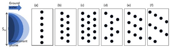
Figure 1.
Schematic diagram of NPRW configurations to capture contaminants in ground water in (a) single transect, (b) double transects, (c) conventional triple transects, (d) triple transects in zigzag array, and (e,f) sawtooth array in three- and four-transects. Sw is the plume width.
A single transect configuration is an array of wells arranged perpendicular to the groundwater flow direction (Figure 1a). Unlike the trench-type PRB, which has a horizontally continuous structure, the reactive wells in NPRWs are spaced apart. This allows the contaminated groundwater to flow downgradient through the gap between the wells. The multi-transect configuration can be constructed by placing two or three transects of the reactive wells slightly diagonally along the groundwater flow direction (Figure 1b,c). The center of the reactive well located in the downgradient transect is located in the middle of two reactive wells in the upgradient area. The multi-transect configuration can capture the contaminant plume completely by repeated treatment in the reactive wells on the second and third transects. However, the performance of NPRWs in preventing pollution is affected by several configuration factors such as well spacing, distance between transects, and number of wells and transects [28,31].
A diagonal arrangement of reactive wells (zigzag array) was proposed as a more efficient well configuration (Figure 1d) in which the zigzag array transect consists of linear segments arranged at a 45-degree angle with respect to the direction of groundwater flow. This configuration performed effectively in terms of reducing the maximum concentrations, as well as the residual plume area [31].
2.2. Modeling Groundwater Flow and Contaminant Transport
A numerical simulation on a hypothetical contaminated site was conducted to evaluate the remediation of contaminated groundwater and prevention of contaminant spreading. The conceptual model of the contaminated aquifer assumed that groundwater, which was in an unconfined aquifer, was in steady state and was contaminated by heavy metals. The aquifer had 10 m of saturated thickness and 0.01 hydraulic gradient. The geologic media was modeled with three layers: an unsaturated zone, unconfined aquifer, and impermeable layer. In the simulation, the NPRW was inserted by boring wells in various configurations from the unsaturated zone to the unconfined aquifer for contaminant remediation.
A three-dimensional modeling domain was constructed to numerically simulate the groundwater flow and contaminant transport. The model domain (20 × 5 × 10 m) was divided into 40,000 square grid elements. The specified head boundary at the west and east edges of the model produced a regional hydraulic gradient of 0.01 eastward. The north, south, and bottom edges of the model were defined as no-flow boundaries. Hydraulic conductivities of 3 × 10⁻⁴ cm/s and 0.1 cm/s were assigned to the aquifer and wells, respectively. The hydraulic conductivity of aquifer was selected within the range of values (0.00864~0.864 m/d) generally observed in the porous medium mainly composed of sand [38]. Wells containing the reactive media were arranged in the middle of the domain following a saw-tooth array (Figure 1e,f). The effective porosity was 0.30 and 0.35 for the aquifer and the reactive material, respectively.
The contaminant source was located on the west edge of the domain and continuously supplied water with 10 mg/L of the contaminant to all the layers in the domain. The plume width (Sw) was set equal to the distance between the centers of the wells on the edges of the upgradient transect. Longitudinal and transverse horizontal dispersivity were given as 0.01 m and 0.001 m, respectively. Wells were simulated as contaminant sinks with a concentration of 0 mg/L; the model assumed that reactive media completely removed any contaminants entering the wells.
This study employed three numerical models, MODFLOW [39], MODPATH [40], and MT3DMS [41] to simulate groundwater flow, particle tracking, and solute transport, respectively, in a hypothetical unconfined aquifer. MT3DMS [42] can be used to simulate changes in concentrations of miscible contaminants in groundwater considering advection, dispersion, diffusion, and some basic chemical reactions with various types of boundary conditions and external sources or sinks [42]. It uses the following equation:
where C is the concentration of contaminants dissolved in groundwater, t is the time, xi is the distance along the respective Cartesian coordinate axis, Dij is the hydrodynamic dispersion coefficient, νi is the seepage or linear pore water velocity, qs is the volumetric flux of water per unit volume of aquifer representing sources (positive) and sinks (negative), Cs is the concentration of the sources or sinks, θ is the porosity of the porous medium, and is the chemical reaction term. The transport equation is related to the flow equation as follows:
where Kii is the hydraulic conductivity value along the i coordinate axes (i = x, y, z). The hydraulic head (h) is an element included in the three-dimensional groundwater flow equation, and can be expressed as
where Ss is the specific storage of porous materials. K (hydraulic conductivity tensor) has nine components; however, because the major components of the hydraulic conductivity tensor are generally aligned with the x, y, and z coordinate axes, it is assumed that the non-major components are zero. This assumption is incorporated into the most commonly used flow models, including MODFLOW [39,41]. All groundwater flow simulations employed a preconditioned conjugate gradient (PCG) solver.
2.3. Case Study: Contaminant Removal Using Various Configurations of NPRWs
The effect of various configuration related factors, such as the arrangement, spacing, and size of the wells on the efficiency to prevent contaminant spread was evaluated numerically. In the first case study, the effect of the hydraulic conductivities and well diameter on the contaminant removal was tested for the single NPRW. In the second case, the effect of the well configuration was tested. Here, the NPRWs were simulated with (1) trench-type, (2) single transect, (3) double transect, (4) conventional triple-transect, and (5) triple-transect with sawtooth array installations. All configurations of NPRWs were set with a well diameter of 0.25 m and minimum well spacing (dm) of 1.5 m between the wells. As a control, a trench-type PRB with a 1 m thickness (Tb) was set considering the excavation width of common construction equipment. The contaminated groundwater plume in the simulation of the trench-type-PRB was assumed to have the same width as the trench, which was 3 m to compare the efficiency of contaminant capturing with respect to the PRB configurations. The third case study was tested to evaluate the effect of the minimum well spacing and the number of transects on contaminant removal. The fourth case study was tested to evaluate the effect of well diameter on contaminant removal.
2.4. Analysis of Removal Efficiency
The removal efficiency (Re) of NPRW was evaluated using the mass budget at the left and right boundaries using the following equation:
where Sw is the width of the contaminant plume (m), and C0 is the input concentration of contaminant (mg/L). In addition, the number of wells for construction was evaluated to compare the efficiency of individual wells in each configuration of the NPRW.
3. Results and Discussion
3.1. Practical Configuration of NPRW
3.1.1. Removal of Contaminant Plume by Single NPRW
To evaluate the capture width of single NPRW, the numerical case study was performed using different conditions of hydraulic conductivity and radius of the material filling in NPRW. Here the capture width was determined by measuring the width of the decontaminated water plume that appeared downstream of the well (Figure 2a). When the hydraulic conductivity of the reactive material (Kw) was higher than that of the surrounding geologic media (Ka), the capture width (d2) was wider than their radius (d1). The ratio of capture width over well diameter (d2/d1) increased depending on the hydraulic conductivity difference (Kw/Ka) (Figure 2b). At Kw/Ka higher than 25, the capture width, d2/d1, reached a maximum 1.9. Without loss of consistency, as the diameter of a NPRW increased, the capture width also increased linearly (Figure 2c). Previous researches already reported the dependency of capture with of NPRW on diameter as well as hydraulic conductivity of well. They also reported that the maximum capture width (d2/d1) could not exceed 2.0 even by using highly permeable material [25,28,30]. In order to block a given width of contaminant plume using NPRWs, an efficient well arrangement is important.
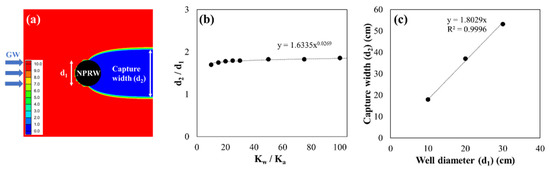
Figure 2.
Capture width of a NPRW according to ratio between the hydraulic conductivities of the geologic media and the filling material (Kw/Ka): (a) determination of capture width from the simulation (in case of d1 = 0.2m); (b) relationship between the capture width and hydraulic condition (Kw/Ka); (c) relationship between the capture width and well diameter.
3.1.2. Configurations of NPRW Considering Field Constraints
To design the optimum configuration of the NPRW, various configurations were devised by changing the well diameter and the transverse distance between the wells in the upgradient area to minimize the number of reactive wells and reduce the contaminant plume leakage. The well diameter is important for determining the construction equipment and the amount of reactive material filled inside the non-pumping wells. Depending on the purpose, wells of various diameters can be used for NPRWs. However, it is necessary to select a well with an appropriate diameter because the construction technology is limited, and the cost increases with increasing diameter.
Well spacing is another important factor constraining well construction. Because narrow well spacing can increase the collapse risk of the geologic media, the engineers constructing the wells are advised to provide enough space between the wells. Here, the minimum well spacing is the minimum distance between any two wells that the engineer considers technically safe and is widely applied to prevent the collision of any well [43,44]. In our recent field work, the new wells were subject to a restriction condition that they must be at least 1 m from the existing wells. Because the close distance between the designed wells is likely to cause well instability, it can be a construction constraint at the field site.
However, the wider the spacing between the wells, the more groundwater may bypass the reactive wells, so the closer the well spacing, the higher the decontamination efficiency [45]. Therefore, when determining the spacing between wells, structural stability must be considered as well as pollutant removal efficiency. For example, the configuration of the zigzag array could not meet the minimum well spacing constraint applied on field (Figure 3a). To prevent collapse due to adjacent wells being too close, well spacing at least must be greater than minimum well spacing. And at the same time, to reduce the bypass of groundwater, it is necessary to properly determine the effective well spacing so that the spacing between the adjacent wells is not too wide. The minimum well spacing serves to determine the well spacing so that NPRW can be realistically designed, and the effective well spacing determines the appropriate well configuration so that NPRW can treatment groundwater economically and efficiently. Depending on the determination of effective well spacing, NPRW can have various configurations, and in this work, we proposed NPRW with sawtooth array (Figure 3b). The NPRW with sawtooth array is a practical configuration that satisfies the minimum well spacing, and requires fewer wells than the previously proposed NPRW when treat contaminant plume of the same width.
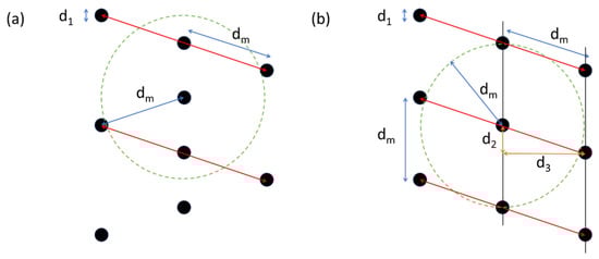
Figure 3.
Well spacing in NPRWs: (a) zigzag array and (b) sawtooth array. Here, d1 is well diameter; d2 is the plume width captured by a single well; d3 is the minimum distance between the transects; dm is minimum well spacing; the red line means unit segment; the green dashed circle means locations dm away from the center of a well located in the middle of well arrays. These configurations were constructed by assuming d1 = 0.25 m, dm = 1.5 m, Si = dm, and the hydraulic conductivity of the reactive media in the well is sufficiently higher than that of aquifer.
3.1.3. Process to Design NPRW Considering Field Constraints
An efficient NPRW satisfying the minimum well spacing constraint can be designed by the following processes.
- (1)
- Determine the well diameter (d1) that can be applied to the well construction site.
- (2)
- Determine an imaginary pollution barrier line perpendicular to the direction of groundwater flow and longer than the width of the contaminant plume, Sw.
- (3)
- Predict the capture width (d2) of a single well by considering the well diameter (d1) and the hydraulic conductivity of the reactive media and the geologic media. Previous studies reported that a highly permeable single well could capture contaminated groundwater flowing through a width 1.8–2.0 times greater than the well diameter [28,30]. The plume width captured by a single well (d2) is:where α is the groundwater capture efficiency of a well, which is defined as the ratio of the capture width to the diameter of a single well, d1.
- (4)
- Place the reactive wells along the contamination blocking line, spaced at a distance of d2.
- (5)
- In the case where d2 is closer than the minimum well space dm, the unit well segment (for example, the red lines in Figure 3b) is defined so that the width of the unit segment, Si, is greater than dm.where N is the number of wells in the unit segment (integer).
- (6)
- Optimize the configuration of the unit segment considering the site conditions, including the minimum well spacing. For example, some of the wells included in the unit segment may be moved in the downstream direction, thereby satisfying the limiting condition for minimum well spacing. Then, if a new well is installed in a place separated from the wells in the preceding transect by distance d2 and d3, in the transverse and longitudinal directions, respectively, the limiting condition of minimum well spacing can be satisfied. Here, d3 is the minimum distance between the transects, and it can be calculated by
- (7)
- The number of segments is determined as Ns (integer), using the ratio of the width of the contaminant plume, Sw, to the width of the unit segment, Si. The arrangement of NPRW should be wider than the width of the contaminant plume (Sw) to prevent contaminants from spreading downgradient. To prevent the spread of contaminants completely, the following condition should be satisfied:
- (8)
- The designed PRB system can be completed by arranging Ns unit segments along the pollution barrier line.
3.1.4. Sawtooth Array for Multiple Transect Configurations of NPRWs
The design of the unit segment is the most important process for the design of a NPRW. The conventional configurations of multi-transects may be limitations in terms of minimum well spacing to prevent the collision of close wells. Here, we proposed a novel configuration of NPRW, i.e., the sawtooth array, to fulfill the minimum well spacing (dm) requirement of the well construction site. The sawtooth configuration is an array of reactive wells in the asymmetric form that achieves sufficient contaminant removal and satisfies the minimum well spacing requirement. Figure 1e and Figure 4b show three segments of NPRWs in sawtooth form. Figure 3b shows that the wells are spaced apart in the longitudinal direction of the groundwater flow considering the allowable minimum distance.
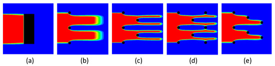
Figure 4.
Numerical modeling of contaminant transport through various PRB configurations: (a) trench-type PRB, (b) single transect, (c) double transect, (d) conventional triple transect, and (e) triple transect with sawtooth array of reactive wells. These configurations were constructed by assuming that well diameter, d1 = 0.25 m and minimum well spacing, dm = 1.5 m, and the hydraulic conductivity of the reactive media in the well was sufficiently higher than that of aquifer.
Depending on the site conditions and applicable technology, the unit segment should be adjusted. If the diameter of the well is small, or the minimum well spacing required by the site is large, additional wells may need to be added to the unit segment. Figure 1f shows the sawtooth array of reactive wells in a four-transect configuration.
3.2. Modeling Contaminant Transport through NPRWs
3.2.1. Prevention of Contaminant Spread by NPRW
Contaminant transport through various PRB configurations was simulated numerically. Trench- and NPRWs were used to capture 3 m of contaminated plume in numerical simulations (Figure 4). The simulations tested different designs of multiple transect configurations considering the minimum well spacing. As a control, the conventional trench-type PRB was also modeled (Figure 4a), which could capture the contaminant plume completely. For groundwater contamination that occurs at a shallow depth where trenches can be installed, it is possible to completely capture the contamination. However, considering the limitations of deep aquifer remediation and the enormous amount of reactive media consumed to form a trench, the NPRWs, as shown in Figure 4b–e, can be used as an alternative PRB configuration.
If the reactive wells were placed in a line and considered the field constraints, the single transect configuration could not prevent the contaminants from spreading downstream. Because each reaction well (d1 = 0.25 m) could capture contamination twice the width of the well diameter at most, the wells separated by 1.5 m intervals leaked contamination downstream (Figure 4b).
The multiple transect configuration formed by adding wells downstream of the first transect could be an alternative configuration to complement the contaminant leakage (Figure 4c–e). The double transect increased the contaminant removal efficiency, because the second well transect located downgradient could capture the contaminant plume passing through the first transect (Figure 4c). Under the assumed well diameter and minimum well spacing, an additional transect was necessary for complete contaminant removal.
When designing the configuration of a NPRW with three or more transects, various arrangements are possible, and the contaminant removal performance may vary substantially. The triple-transect configuration using a zigzag arrangement (Figure 3a) could not be constructed on site because the distance between the wells in the second transect and the adjacent wells was closer than the minimum separation distance. Figure 4d shows a conventional triple-transect configuration in which the third row of reaction wells is additionally constructed downstream of the first row in the double-transect configuration. This structure could not remove the contaminants that have leaked from the second transect but could remove contaminants that had not been completely removed by the first transect. The simulated contaminant plume through the sawtooth configuration shows complete prevention of contaminant spread (Figure 4e).
3.2.2. Evaluation of NPRW Performance
The performance of NPRWs was evaluated quantitatively using the contaminant removal efficiency and the number of wells in the unit segment, respectively (Figure 5). When wells are arranged in a multiple transect configuration considering the minimum separation distance, if the number of wells in a unit segment is small (when the number of transects is insufficient), sufficient contaminant removal performance cannot be expected. Even in a configuration of three or more transects, the contaminant removal efficiency may differ depending on the well arrangement method. These results suggest that the sawtooth array of NPRW could be used effectively in contaminant spreading prevention using a small number of wells while maintaining minimum well spacing for technical safety. In addition, to completely capture the contaminant plume using multiple transects of reactive wells, the sawtooth array could also be the optimal arrangement for the reactive wells considering the removal efficiency as well as the field constraints for the well construction.
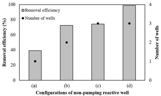
Figure 5.
Removal efficiency (Re) and number of wells in unit segment (N) of NPRWs: (a) single transect, (b) double transect, (c) conventional triple transect, and (d) triple transect with sawtooth array of reactive wells.
The optimization of the well configuration should be considered based on two criteria—the stability of well construction and contaminant removal. Among these criteria, if the construction stability of the well is prioritized to classify the NPRW, the number of transects can be a major factor in determining the shape of unit transect. For effective arrangement of the reactive wells, the number of transects is equivalent to the number of wells in a unit segment (N). Then, single- and double-transect configurations, shown in Figure 5a,b, could be the practical configurations for the cases of N = 1 and 2. The sawtooth array, shown in Figure 5d, could be a practical configuration for N = 3. Limited to these efficient multi-transect well configurations, there is a proportional relationship between the number of wells in the unit segment (N) and the removal efficiency (Re).
3.3. Prediction of the Contaminant Removal Using Multiple Transect NPRW
3.3.1. Performance Curve of Multiple Transect NPRW
Contaminant removal by NPRWs with multi-transects is affected by the design factors for the unit segment, such as d1, d2, α, dm, and Si, as well as N. Here, d2 and α are dependent on the site conditions, such as hydraulic conductivity, and can vary depending on the uncertainties due to the heterogeneity of the geologic media. Considering the dependency between dm and Si, the configuration factors that determine the removal rate can be deduced by d1, Si, and N. Then, the performance of NPRW can be calculated using the relationship of removal efficiency with well diameter (d1), width of unit segment (Si), and number of wells (N). Here, we assumed that the contaminated groundwater with constant concentration, C0, flowed with a constant flux q in laminar flow. Then, the mass input of contaminant into unit segment for the unit depth, Fin, was as follows:
The reactive material in the well was assumed to remove the contaminant completely and instantaneously. Then, the mass flux removed was:
Then, the ratio of contaminant removal (Re) for a unit segment could be expressed as
By Equation (5),
By setting the width of the unit segment Si equal to the minimum well spacing, dm, Re could be expected as follows:
This equation explains the removal efficiency relationship as a function of field constraint (dm), geological condition (α), and well configuration (d1 and N). Therefore, this equation can be used to construct the performance curve of multiple transect NPRWs.
3.3.2. Effect of Minimum Well Spacing and Well Configurations on PRB Performance
Numerical simulations of contaminant transport were conducted for various multiple transect configurations considering minimum well spacing to validate the performance curve. Figure 6 shows the effect of the minimum well spacing (dm) and number of wells (N) in multiple transect configurations on the removal ratio (Re). Here, the well diameter (d1) was assumed to be 0.25 m, and the width of the interval was set equal to the minimum well spacing. The smaller the N and larger the Si (=dm), the greater the contaminant plume that flowed downstream untreated.
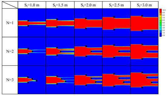
Figure 6.
Simulation of steady-state solute transport through single transect (N = 1), double transect (N = 2), and sawtooth configurations (N = 3) of NPRW under various minimum well spacings, dm. Here, the well diameter (d1) was assumed as 0.25 m, and the width of interval was set equal to the minimum well spacing.
The contaminant removal ratios for each simulation were calculated and are presented in Table 1. For a given configuration with the same number of transects, the removal ratio decreased with increasing minimum well spacing (or width of unit segment). A single transect had low removal efficiency even at the smallest minimum well spacing (1.0 m), confirming that additional downgradient transects need to be installed, such as those in double transect or sawtooth configurations. For a given well spacing, the removal efficiency increased in the order of single, double, and triple (sawtooth arrays) configurations. For instance, at dm = 1.5 m, the removal efficiency was only 31% for a single transect, but 63% and 95% for double transect and the sawtooth array, respectively. A contaminant plume passing between the upgradient transect of NPRW was trapped in the downgradient transects, resulting in increased removal efficiency. Here, we found that the sawtooth configurations of NPRWs could be a practical configuration that could achieve high removal efficiency with a small number of wells while satisfying the minimum well spacing considering the construction constraints.

Table 1.
Ratio of contaminant removal by multiple transect NPRWs according to the minimum well spacing, dm (or width of unit segment, Si) and in various configurations (number of wells, N).
After a minimum well spacing has been proposed in the field, it is necessary to determine the well diameter. The well diameter should be proportional to the capture width of each well, because fewer wells are required when well diameters are larger. However, as the well diameter increases, the well boring cost and the required mass of reactive material also increase. Therefore, additional factors such as availability of equipment and cost of well construction should be considered in determining the well diameter. The relationship between the diameter and the contamination removal performance was confirmed. This was done through a simulation of contaminant spread through a NPRW in sawtooth array configuration (N = 3), according to the well diameter and minimum well spacing (or width of unit segment) (Figure 7). When d1 was smaller and Si (dm) was larger, a greater proportion of the contaminant plume flowed downstream untreated. The contaminant removal efficiencies for the simulated PRB configurations were calculated and are presented in Table 2.
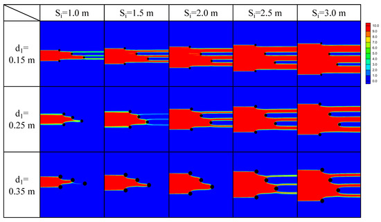
Figure 7.
Simulation of steady-state solute transport through NPRW with triple transect in sawtooth array (N = 3) for various well diameters d1 with the minimum well spacing dm. Here, the width of unit segment Si was set equal to dm.
Table 2.
Ratio of contaminant removal by triple transect NPRW (sawtooth array) according to the well diameter d1 and the minimum well spacing dm (or width of unit segment, Si).
The simulated contaminant removal was plotted as a function of minimum well spacing (dm) and the number of wells (Figure 8a). The simulated contaminant removal of triple transect PRB was also plotted as a function of well diameter (d1) and minimum well spacing (Figure 8b). The contaminant removal efficiencies by NPRWs were calculated numerically and compared with those expected using Equation (13). Using the trial and error method, the curves expected by Equation (13) were well-fitted to the simulated contaminant removal efficiency, when α = 1.85. This value is similar to the maximum value reported in previous research [28,30]. Therefore, the simple relationship between contaminant removal efficiency and Si and N could be used as the performance curve of NPRWs.
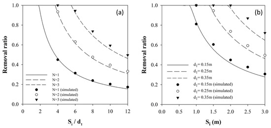
Figure 8.
Performance curves of (a) NPRW according to various configurations and well spacings (Si), and (b) triple transect NPRWs with various well diameter (d1) and well spacing (Si).
3.4. Design of Practical Configurations of NPRW Based on the Performance Curves
The performance curve presented above can be used to determine the NPRW design factors that meet the construction constraints of the site and achieve the decontamination goal. For example, when the minimum well spacing (dm) is presented as a construction constraint considering site geological conditions, the performance curve of Re vs. dm/d1, such as in Figure 8a, can be used to determine the other design element of the unit segment. To do this, it is necessary to examine the constructible well diameter d1, determine the range of available dm/d1, and then determine the N that can achieve the decontamination target.
When the constructible well diameter d1 is limited, Figure 8b can be used to determine the number of wells to achieve the target removal efficiency. For the selected well diameter, the maximum decontamination efficiency can be expected at the point where the performance curve of d1 and the line of Si = dm meet. If this expected efficiency is less than the target efficiency, it is necessary to increase the number of wells in the unit segment.
The effect of the hydraulic conductivity of the reactive media is reflected through the value of α in this prediction of contamination removal. By adjusting α, the hydraulic conductivity and heterogeneity of the aquifer can be reflected in the well configuration design. Adjustment by reducing α can be a conservative design method that considers factors such as inaccuracies in site characterization and non-ideal performance of reactive materials.
4. Conclusions
The NPRW is proposed as a passive treatment method for contaminated groundwater in deep subsurface environments. Various well configurations have been developed to effectively prevent the spread of groundwater contaminants. In sites where multiple wells are constructed adjacent to each other, sufficient distance between wells is recommended to ensure ground stability and well structure safety. Therefore, the minimum separation distance between wells must be considered as an important limiting condition for efficient NPRW design. Under these constraints, a well array with a single transect requires wells with a diameter as large as the minimum well spacing to block groundwater contamination. However, when the size of the well is large, well construction becomes difficult and the cost increases rapidly. The contaminant leaks that occur between small diameter wells spaced apart can be compensated by configurations with multiple transects that install additional wells downstream; however, the number of wells doubles or triples, increasing cost. Therefore, a practical design of well configurations that uses an appropriate well size and optimizes the arrangement is required. In this research, we proposed a novel triple transect configuration considering the removal efficiency as well as the constraints in the well construction field (well diameter and minimum well spacing). The novel NPRW has a triple or quadruple transect configuration of reactive wells arranged in a sawtooth shape. The number of wells has been optimized for sufficient contaminant removal. The contaminant removal performance of the NPRWs with multiple transect configurations could be estimated using the performance curve developed from the relationship of contaminant removal efficiency with well spacing and well diameter. This performance curve allows the selection of practical configurations of NPRWs considering the field conditions, the construction constraints (minimum well spacing and well diameter), and the target removal efficiency of contaminants. The sawtooth configuration and performance curve proposed in this study are expected to be used for the practical design of configurations of NPRWs with respect to well diameter and well spacing under field conditions. It should be noted that since this study focused on designing the feasible construction of NPRWs, it was assumed that the reactive material filled in the wells immediately removes contaminants. For a more practical design of NPRWs with sawtooth array, the diameter of well can be increased or the well spacing can be decreased depending on the performance of the reactive material, and if necessary, a conservative design can be made by applying a safety factor to the performance curve. For this, follow-up studies are required.
Author Contributions
J.-Y.G. performed writing—original draft and visualization. J.-H.K. performed conceptualization and validation. Y.J.L. performed supervision and funding acquisition. S.L. performed writing-review and editing; project administration. All authors have read and agreed to the published version of the manuscript.
Funding
This work was supported by the Korea Environmental Industry & Technology Institute (KEITI) through the underground environmental pollution risk management technology development business program, funded by the Korea Ministry of Environment (MOE) [grant number 2018002470002, ARQ202101728001]; and the National Research Foundation of Korea (NRF) grant funded by the Korea Ministry of Science and ICT [grant number NRF-2017R1C1B3009500].
Institutional Review Board Statement
Not applicable.
Informed Consent Statement
Not applicable.
Data Availability Statement
Data sharing not applicable.
Acknowledgments
This work was supported by the Korea Environmental Industry & Technology Institute (KEITI) and the National Research Foundation of Korea (NRF).
Conflicts of Interest
The authors declare no conflict of interest.
References
- Price, S.J.; Ford, J.R.; Cooper, A.H.; Neal, C. Humans as major geological and geomorphological agents in the Anthropocene: The significance of artificial ground in Great Britain. Philosl. Trans. R. Soc. A 2011, 369, 1056–1084. [Google Scholar] [CrossRef] [PubMed]
- Fetter, C. Applied Hydrogeology, 4th ed.; Prentice-Hall: Upper Saddle River, NJ, USA, 2001; 598p. [Google Scholar]
- Singhal, B.B.S.; Gupta, R.P. Applied Hydrogeology of Fractured Rocks; Springer Science & Business Media: Berlin, Germany, 2010. [Google Scholar]
- Younger, P.L. Groundwater in the Environment: An introduction; John Wiley & Sons: Hoboken, NJ, USA, 2009. [Google Scholar]
- Powell, R.M.; Powell, P.D.; Puls, R.W. Economic Analysis of the Implementation of Permeable Reactive Barriers for Remediation of Contaminated Ground Water; U.S. Environmental Protection Agency: Washington, DC, USA, 2002.
- Hashim, M.A.; Mukhopadhyay, S.; Sahu, J.N.; Sengupta, B. Remediation technologies for heavy metal contaminated groundwater. J. Environ. Manag. 2011, 92, 2355–2388. [Google Scholar] [CrossRef] [PubMed]
- Ludwig, R.D.; McGregor, R.G.; Blowes, D.W.; Benner, S.G.; Mountjoy, K. A permeable reactive barrier for treatment of heavy metals. Ground Water 2002, 40, 59–66. [Google Scholar] [CrossRef] [PubMed]
- Woinarski, A.Z.; Stevens, G.W.; Snape, I. A natural zeolite permeable reactive barrier to treat heavy-metal contaminated waters in Antarctica—Kinetic and fixed-bed studies. Process. Saf. Environ. Prot. 2006, 84, 109–116. [Google Scholar] [CrossRef]
- Grau-Martinez, A.; Torrento, C.; Carrey, R.; Soler, A.; Otero, N. Isotopic evidence of nitrate degradation by a zero-valent iron permeable reactive barrier: Batch experiments and a field scale study. J. Hydrol. 2019, 570, 69–79. [Google Scholar] [CrossRef]
- Robertson, W.D.; Blowes, D.W.; Ptacek, C.J.; Cherry, J.A. Long-term performance of in situ reactive barriers for nitrate remediation. Ground Water 2000, 38, 689–695. [Google Scholar] [CrossRef]
- Robertson, W.D.; Vogan, J.L.; Lombardo, P.S. Nitrate removal rates in a 15-year-old permeable reactive barrier treating septic system nitrate. Ground Water Monit. R. 2008, 28, 65–72. [Google Scholar] [CrossRef]
- Stewart, D.I.; Csovari, M.; Barton, C.S.; Morris, K.; Bryant, D.E. Performance of a functionalised polymer-coated silica at treating uranium contaminated groundwater from a Hungarian mine site. Eng. Geol. 2006, 85, 174–183. [Google Scholar] [CrossRef]
- Guerin, T.F.; Horner, S.; McGovern, T.; Davey, B. An application of permeable reactive barrier technology to petroleum hydrocarbon contaminated groundwater. Water Res. 2002, 36, 15–24. [Google Scholar] [CrossRef]
- McGovern, T.; Guerin, T.F.; Horner, S.; Davey, B. Design, construction and operation of a funnel and gate in-situ permeable reactive barrier for remediation of petroleum hydrocarbons in groundwater. Water Air Soil Poll 2002, 136, 11–31. [Google Scholar] [CrossRef]
- Smith, C.C.; Anderson, W.F.; Freewood, R.J. Evaluation of shredded tyre chips as sorption media for passive treatment walls. Eng. Geol. 2001, 60, 253–261. [Google Scholar] [CrossRef]
- Bekele, D.N.; Du, J.H.; de Freitas, L.G.; Mallavarapu, M.; Chadalavada, S.; Naidu, R. Actively facilitated permeable reactive barrier for remediation of TCE from a low permeability aquifer: Field application. J. Hydrol. 2019, 572, 592–602. [Google Scholar] [CrossRef]
- Lai, K.C.K.; Lo, I.M.C.; Birkelund, V.; Kjeldsen, P. Field monitoring of a permeable reactive barrier for removal of chlorinated organics. J. Environ. Eng. 2006, 132, 199–210. [Google Scholar] [CrossRef]
- Vogan, J.L.; Focht, R.M.; Clark, D.K.; Graham, S.L. Performance evaluation of a permeable reactive barrier for remediation of dissolved chlorinated solvents in groundwater. J. Hazard. Mater. 1999, 68, 97–108. [Google Scholar] [CrossRef]
- Hosseini, S.M.; Ataie-Ashtiani, B.; Kholghi, M. Bench-Scaled Nano-Fe0 Permeable Reactive Barrier for Nitrate Removal. Ground Water Monit. Remediat. 2011, 31, 82–94. [Google Scholar] [CrossRef]
- Xu, J.; Wang, Y.; Weng, C.; Bai, W.L.; Jiao, Y.; Kaegi, R.; Lowry, G.V. Reactivity, Selectivity, and Long-Term Performance of Sulfidized Nanoscale Zerovalent Iron with Different Properties. Environ. Sci. Technol. 2019, 53, 5936–5945. [Google Scholar] [CrossRef]
- Vignola, R.; Bagatin, R.; D’Auris, A.D.F.; Flego, C.; Nalli, M.; Ghisletti, D.; Millini, R.; Sisto, R. Zeolites in a permeable reactive barrier (PRB): One year of field experience in a refinery groundwater—Part 1: The performances. Chem. Eng. J. 2011, 178, 204–209. [Google Scholar] [CrossRef]
- Wang, J.; Hou, L.A.; Yao, Z.K.; Jiang, Y.H.; Xi, B.D.; Ni, S.Y.; Zhang, L. Aminated electrospun nanofiber membrane as permeable reactive barrier material for effective in-situ Cr(VI) contaminated soil remediation. Chem. Eng. J. 2021, 406, 126822. [Google Scholar] [CrossRef]
- Zhao, P.P.; Yu, F.; Wang, R.Y.; Ma, Y.; Wu, Y.Q. Sodium alginate/graphene oxide hydrogel beads as permeable reactive barrier material for the remediation of ciprofloxacin-contaminated groundwater. Chemosphere 2018, 200, 612–620. [Google Scholar] [CrossRef]
- Liu, Y.Y.; Mou, H.Y.; Chen, L.Q.; Mirza, Z.A.; Liu, L. Cr(VI)-contaminated groundwater remediation with simulated permeable reactive barrier (PRB) filled with natural pyrite as reactive material: Environmental factors and effectiveness. J. Hazard Mater. 2015, 298, 83–90. [Google Scholar] [CrossRef]
- Hosseini, S.M.; Tosco, T. Integrating NZVI and carbon substrates in a non-pumping reactive wells array for the remediation of a nitrate contaminated aquifer. J. Contam. Hydrol. 2015, 179, 182–195. [Google Scholar] [CrossRef] [PubMed] [Green Version]
- Hudak, P.F. Evaluation of reactive well networks for remediating heterogeneous aquifers. J. Environ. Sci. Health A 2008, 43, 731–737. [Google Scholar] [CrossRef] [PubMed]
- Hudak, P.F. Shallow, Non-pumped Wells: A Low-Energy Alternative for Cleaning Polluted Groundwater. Bull. Environ. Contam. Tox. 2013, 91, 107–110. [Google Scholar] [CrossRef] [PubMed]
- Wilson, R.D.; Mackay, D.M.; Cherry, J.A. Arrays of unpumped wells for plume migration control by semi-passive in situ remediation. Ground Water Monit. Remediat. 1997, 17, 185–193. [Google Scholar] [CrossRef]
- Naftz, D.L.; Davis, J.A., III. Deep Aquifer Remediation Tools (DARTs): A New Technology for Ground-Water Remediation; US Geological Survey: Reston, VA, USA, 1999; pp. 2327–6932.
- Freethey, G.W.; Naftz, D.L.; Rowland, R.C.; Davis, J.A. Deep aquifer remediation tools: Theory, design, and performance modeling. In Handbook of Groundwater Remediation Using Permeable Reactive Barriers; Elsevier: Amsterdam, The Netherlands, 2003; pp. 133–161. [Google Scholar]
- Hudak, P.F. Configuring passive wells with reactive media for treating contaminated groundwater. Environ. Prog. 2008, 27, 257–262. [Google Scholar] [CrossRef]
- Hosseini, S.M.; Tosco, T.; Ataie-Ashtiani, B.; Simmons, C.T. Non-pumping reactive wells filled with mixing nano and micro zero-valent iron for nitrate removal from groundwater: Vertical, horizontal, and slanted wells. J. Contam. Hydrol. 2018, 210, 50–64. [Google Scholar] [CrossRef]
- Erto, A.; Lancia, A.; Bortone, I.; Di Nardo, A.; Di Natale, M.; Musmarra, D. A procedure to design a Permeable Adsorptive Barrier (PAB) for contaminated groundwater remediation. J. Environ. Manag. 2011, 92, 23–30. [Google Scholar] [CrossRef]
- Henry, B.M.; Perlmutter, M.W.; Downey, D.C. Permeable organic biowalls for remediation of perchlorate in groundwater. In In Situ Bioremediation of Perchlorate in Groundwater; Springer: New York, NY, USA, 2009; pp. 177–197. [Google Scholar]
- Klammler, H.; Hatfield, K. Analytical solutions for flow fields near continuous wall reactive barriers. J. Contam. Hydrol. 2008, 98, 1–14. [Google Scholar] [CrossRef]
- Gavaskar, A.R. Design and construction techniques for permeable reactive barriers. J. Hazard. Mater. 1999, 68, 41–71. [Google Scholar] [CrossRef]
- Puls, R.W. Long-term performance of permeable reactive barriers: Lessons learned on design, contaminant treatment, longevity, performance monitoring and cost-an overview. In Soil and Water Pollution Monitoring, Protection and Remediation; Springer: New York, NY, USA, 2006; pp. 221–229. [Google Scholar]
- Joo, J.C.; Lee, D.H.; Moon, H.S.; Chang, S.W.; Lee, S.-H.; Lee, E.; Nam, K. Sensitivity Analysis of Hydrodynamic and Reaction Parameters in Gasoline Transport Conceptual Aquifer Model Based on Hydrogeological Characteristics of Korea. J. Soil Groundw. Environ. 2020, 25, 37–52. [Google Scholar]
- McDonald, M.G.; Harbaugh, A.W. A Modular Three-Dimensional Finite-Difference Ground-Water Flow Model; US Geological Survey: Reston, VA, USA, 1988.
- Pollock, D.W. User’s Guide for MODPATH/MODPATH-PLOT, Version 3: A Particle Tracking Post-processing Package for MODFLOW, the US: Geological Survey Finite-difference Ground-Water Flow Model; US Geological Survey: Reston, VA, USA, 1994.
- Zheng, C. MT3D: A Modular Three-Dimensional Transport Model for Simulation of Advection, Dispersion and Chemical Reactions of Contaminants in Groundwater Systems; SS Papadopulos & Associates: Rockville, MD, USA, 1992. [Google Scholar]
- Zheng, C.; Wang, P.P. MT3DMS: A Modular Three-Dimensional Multispecies Transport Model for Simulation of Advection, Dispersion, and Chemical Reactions of Contaminants in Groundwater Systems; Documentation and User’s Guide. 1999. Available online: https://www.researchgate.net/publication/283742180_MT3D_A_modular_three-dimensional_transport_model_for_simulation_of_advection_dispersion_and_chemical_reactions_of_contaminants_in_groundwater_systems (accessed on 28 September 2021).
- Awotunde, A.A.; Naranjo, C. Well placement optimization constrained to minimum well spacing. In Proceedings of the SPE Latin America and Caribbean Petroleum Engineering Conference, Maracaibo, Venezuela, 21–23 May 2014. [Google Scholar]
- Xiushan, L.; Yinao, S. Description and application of minimum distance between adjacent wells. China Offshore Oil Gas 2000, 12, 31–34. [Google Scholar]
- Eccles, J.; Pratson, L.F.; Chandel, M.K. Effects of Well Spacing on Geological Storage Site Distribution Costs and Surface Footprint. Environ. Sci. Technol. 2012, 46, 4649–4656. [Google Scholar] [CrossRef] [PubMed]
Publisher’s Note: MDPI stays neutral with regard to jurisdictional claims in published maps and institutional affiliations. |
© 2021 by the authors. Licensee MDPI, Basel, Switzerland. This article is an open access article distributed under the terms and conditions of the Creative Commons Attribution (CC BY) license (https://creativecommons.org/licenses/by/4.0/).