Article

Fast Image Reconstruction Technique for Parallel Phase-Shifting Digital Holography

1
Institute of Engineering, Tokyo University of Agriculture and Technology, 2-24-16 Naka-cho, Koganei, Tokyo 184-8588, Japan
2
Applied Electromagnetic Research Center, Radio Research Institute, National Institute of Information and Communications Technology (NICT), 4-2-1 Nukuikitamachi, Koganei, Tokyo 184-8795, Japan
*
Author to whom correspondence should be addressed.
Appl. Sci. 2021, 11(23), 11343; https://doi.org/10.3390/app112311343
Submission received: 5 November 2021 / Revised: 27 November 2021 / Accepted: 29 November 2021 / Published: 30 November 2021

Abstract

:
For incoherent and coherent digital holography, the parallel phase-shifting technique has been used to reduce the number of exposures required for the phase-shifting technique which eliminates zero-order diffraction and conjugates image components. Although the parallel phase-shifting technique can decrease the hologram recording time, the image interpolations require additional calculation time. In this study, we propose a technique that reduces the calculation time for image interpolations; this technique is based on the convolution theorem. We experimentally verified the proposed technique and compared it with the conventional technique. The proposed technique is more effective for more precise interpolation algorithms because the calculation time does not depend on the size of interpolation kernels.

1. Introduction

Digital holography can measure the two-dimensional amplitude and phase distributions of objects without performing spatial scanning. Thus, three-dimensional (3D) structures of objects can be obtained by diffraction analysis, and label-free imaging can be achieved by using phase information. Traditional digital holography uses an interferometer and coherent light [1]; however, the recently developed incoherent digital holography uses a self-interferometer in which incoherent light can be used [2,3,4,5,6,7,8,9,10,11,12]. The use of incoherent light helps in a wide range of applications, such as fluorescence microscopy [2,3,4,5,6,7,8], the 3D measurements of objects under natural light or LED illumination [9,10,11], and the measurement of radiometric temperature [12].
The phase-shifting technique has been used for digital holography to obtain the complex amplitude of a wavefront diffracted from objects by eliminating the zero-order diffraction and conjugate image components [13,14]. Most incoherent digital holography methods use the phase-shifting technique. The phase-shifting technique requires the capture of three or four holograms with different phase shifts. To avoid multiple image exposures, the parallel phase-shifting technique [15,16] was proposed, which obtained the complex-amplitude distribution of an object wave by a single exposure. In this technique, multiple holograms with different phase shifts were recorded by space multiplexing. The parallel phase-shifting technique can be effectively implemented using polarization image sensors [17]. The recently commercialized polarization image sensors have a high resolution (>1000 × 1000) and operate at a video rate or a high frame rate (≥60 Hz) [18]. The use of the parallel phase-shifting technique enables real-time digital holography [19,20,21]. The single-shot recording enables the measurement of short-time phenomena [22,23,24] and rapidly moving microorganisms [25,26]. In addition, the single-shot multi-wavelength incoherent digital holography was demonstrated by using the color polarization image sensor [27] or the polarization-sensitive phase-shifted array [28].
The polarization image sensors consist of four groups of pixels corresponding to the four phase shifts. Pixels with the same phase shifts were extracted to synthesize four images required for the phase-shifting technique. The interpolation or demosaicing technique was used to obtain four pixel values at identical positions for the four images corresponding to the four phase shifts. The parallel phase-shifting technique can reduce the time taken for image capturing; however, the image interpolations require more time. This additional time required for the interpolations will become an obstacle for real-time operations, especially when the resolution of the image sensor increases. In general, interpolation algorithms with higher accuracies require a longer calculation time than those with lower accuracies. Thus, it is equally important to decrease the time required for image interpolations as it is to decrease the time required for calculating the diffraction.
In this study, we propose a technique to reduce the calculation time required for the image interpolations in the parallel phase-shifting technique. In Section 2, the proposed technique is explained. The experimental verification of the proposed technique is shown in Section 3. The discussion is given in Section 4, which is followed by the conclusions in Section 5.

2. Theory

First, we explain the parallel phase-shifting technique using the polarization image sensor [17]. Figure 1a shows the arrangement of the micro-polarizers attached to the pixels of the image sensor. The directions of the polarizing axes of the micro-polarizers are 0°, 45°, 90°, and 135°. When the object and reference waves having circular polarizations in opposite directions interfere on the image sensor, the phase shifts between the two waves captured by the polarized pixels are δ = 0, π/2, π, and 3π/2, as shown in Figure 1b.
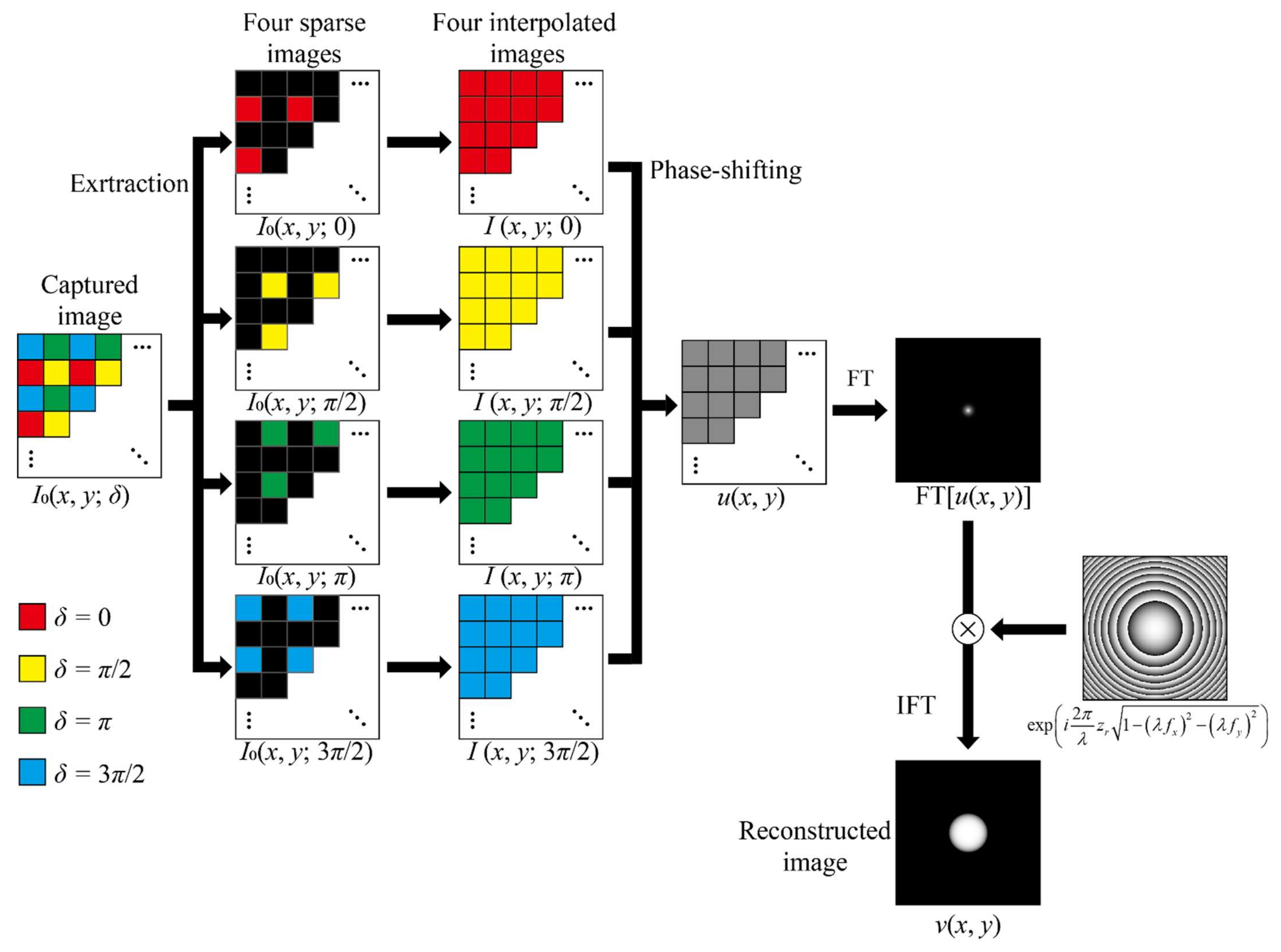
Figure 2 illustrates the calculation procedure of the conventional parallel phase-shifting technique [15,16]. Pixels having the same phase shifts are extracted to obtain four sparse images. The extracted sparse images are represented by Io(x, y; 0), Io(x, y; π/2), Io(x, y; π), and Io(x, y; 3π/2) corresponding to the phase shifts of δ = 0, π/2, π, and 3π/2, respectively. The interpolated images corresponding to the phase shifts of δ = 0, π/2, π, and 3π/2 are denoted by I(x, y; 0), I(x, y; π/2), I(x, y; π), and I(x, y; 3π/2), respectively. We performed image interpolations and obtained four pixel values at identical positions for the four images. The phase-shifting technique provides a complex-amplitude distribution of the object wave on the image sensor by using the following equation:
u x , y = I x , y ; 0 I x , y ; π + i I x , y ; π / 2 I x , y ; 3 π / 2 .
The diffraction calculation is applied to u(x, y) to obtain the reconstructed image. Several kinds of diffraction calculations can be used, such as the Fresnel and Fraunhofer diffraction equations. In this study, we use the angular spectrum representation for the diffraction calculation [29,30]. The angular spectrum method provides the reconstruction image v(x, y) at a distance of zr using the following equation:
v x , y = IFT U f x , f y exp i 2 π λ z r 1 λ f x 2 λ f y 2 ,
where IFT denotes the inverse Fourier transform and U f x , f y is the Fourier transform of u(x, y). The Fourier transform is performed to obtain U f x , f y followed by the multiplication of the phase term. Finally, the inverse Fourier transform gives the reconstructed image.
Next, we explain the calculation technique proposed in this study. When the resolution of the image sensors increases and the fast Fourier transform (FFT) algorithm is used for the diffraction calculation, the calculation time for the Fourier transform increases logarithmically with the resolution. The calculation time for the interpolations increases linearly with the resolution; therefore, this time needs to be reduced. In this study, the interpolation is represented by the convolution of an image and an interpolation kernel. The four interpolated images are obtained for the phase shifts δ = 0, π/2, π, and 3π/2 using the following equation:
I x , y ; δ = I 0 x , y ; δ f x , y ,
where denotes the convolution operation, and f(x, y) represents the interpolation kernel. Various kinds of interpolation algorithms are obtained by changing the interpolation kernel. When the convolution theorem is used, the complex amplitude distribution of the object wave calculated by the angular spectrum method is given as follows:
v x , y = IFT FT u 0 x , y FT f x , y exp i 2 π λ z r 1 λ f x 2 λ f y 2 ,
where FT represents the Fourier transform, and u0(x, y) is given as follows:
u 0 x , y = I 0 x , y ; 0 I 0 x , y ; π + i I 0 x , y ; π / 2 I 0 x , y ; 3 π / 2 .
The above explanation is based on conventional phase-shifting techniques [13,31].
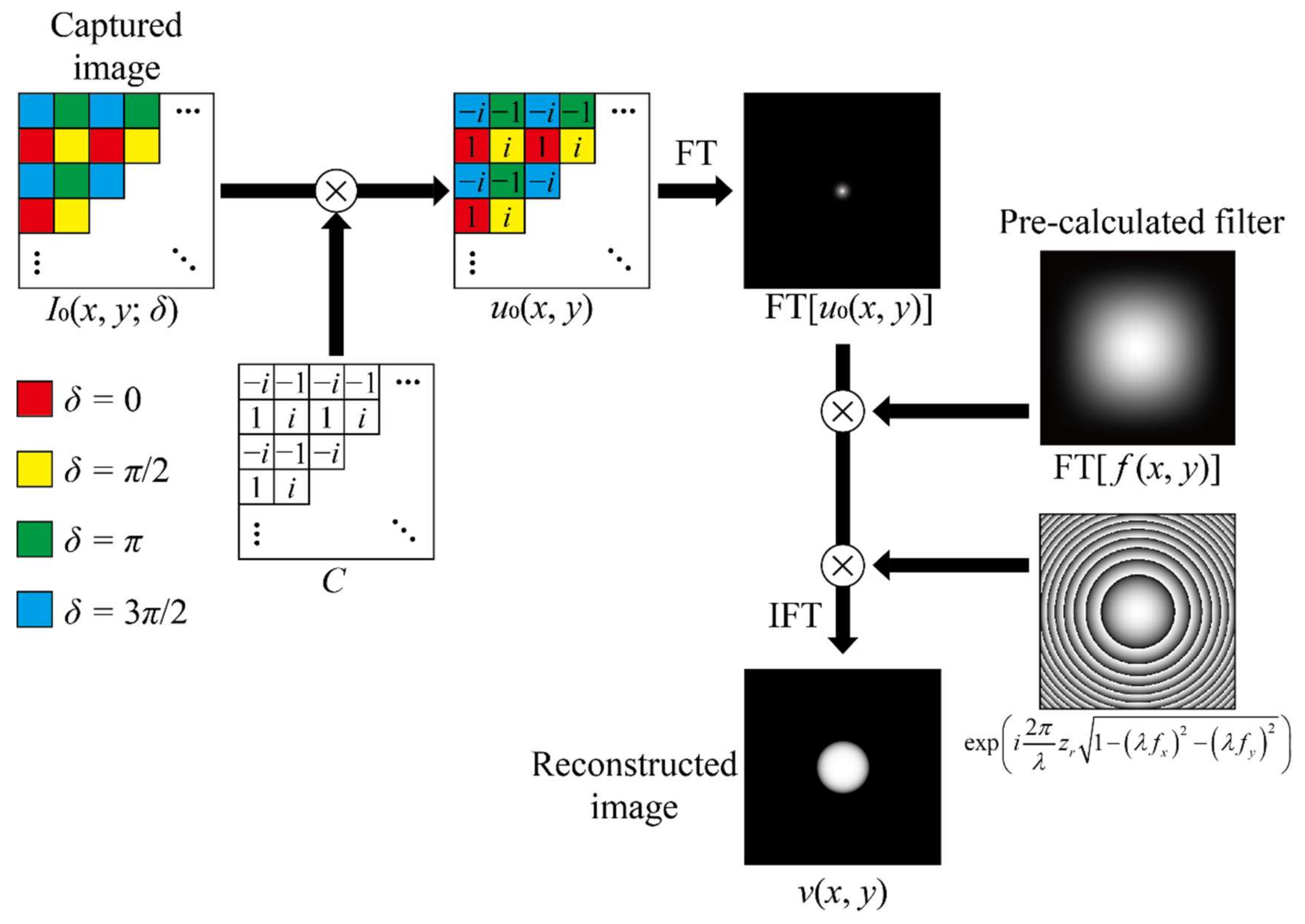
Figure 3 depicts the proposed technique. The image extractions and interpolations are removed. The image captured by the image sensor is multiplied by the complex-number matrix represented by C to obtain u0(x, y), and the Fourier transform is performed. Then, the Fourier transform of the interpolation kernel is multiplied, which is followed by the multiplication of the phase term. Finally, the inverse Fourier transform is performed to obtain the reconstructed image.
The proposed technique completely removes the four image-interpolation calculations from the calculation procedure. However, two multiplication operations using C and the Fourier transform of the kernel are added. The Fourier transform of the kernel can be calculated in advance. Image interpolation generally requires more time than image multiplication. Therefore, the proposed technique can reduce the calculation time for the parallel phase-shifting technique.
When the Fourier transform of the interpolation kernel is calculated in advance, the calculation time required for the proposed technique does not depend on the size of the interpolation kernel. The kernel size depends on the interpolation algorithm, and the kernel sizes usually increase with the increase in the quality of the image interpolation algorithms. Research [32] has shown that the root mean square error of the reconstructed images decreased when interpolation algorithms of high accuracy were used, such as the bicubic interpolation (having kernel size of 7 × 7). The proposed technique can be combined with any diffraction calculation using a Fourier transform, other than the angular spectrum technique.
The proposed technique assumes that the interpolation process is space-invariant. Recently, space-variant techniques [33] have been developed for more precise image interpolation. Because these interpolation processes cannot be expressed using the convolution operation, the proposed technique cannot be used.

3. Experiments

The proposed technique was verified experimentally. The experimental system was constructed based on the Fresnel incoherent correlation holography (FINCH) [3,4,5,6,7].
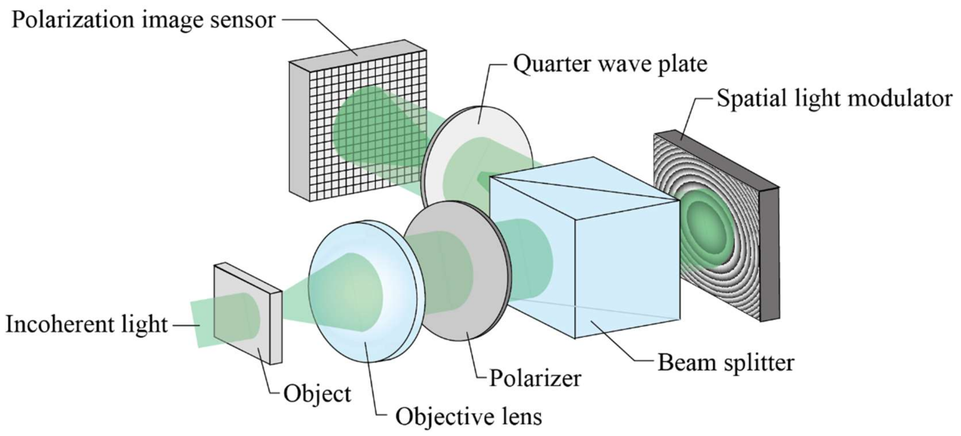
Figure 4 illustrates the FINCH recording system. The objective lens provides a converging wavefront with incoherent light diffracted from an object. The polarizer transforms the incoherent light into linearly polarized light with a polarization angle of 45°. The phase-modulation spatial light modulator (SLM) modulates the phase of the linearly polarized light in either the horizontal direction or the vertical direction but does not modulate the phase of the linearly polarized light in the orthogonal direction. A quadratic phase distribution is displayed on the phase-modulation SLM so that the horizontally and vertically polarized lights have wavefronts with different radii of curvature. Then, the quarter-wave plate transforms the horizontally and vertically polarized lights into right-handed and left-handed circularly polarized lights. Finally, the polarization image sensor is used to record the interference of the two circularly polarized lights.
An LED with a central wavelength of 525 nm and a bandwidth of 30 nm was used as an incoherent light source. We used SLM-100 (Santec Corporation, Aichi, Japan) with a resolution of 1440 × 1050 as a phase-modulation SLM; a pixel pitch of 10.4 μm was used. The polarization camera was VP-TRI050S-P (Lucid Vision Labs, Inc., Richmond, BC, Canada), which had a resolution of 2448 × 2048 and a pixel pitch of 3.45 μm. The central 2048 × 2048 pixels were used for hologram recording. The focal length of the objective lens was 20 mm, and the focal length of the quadratic phase distribution displayed on the SLM was 600 mm. The theoretical minimum resolvable distance was 1.60 μm [6]. A negative test target USAF1951 was used as a recording object. The calculations were performed using a personal computer (Intel Core i7-8550U 4.0GHz CPU, 8GB RAM).
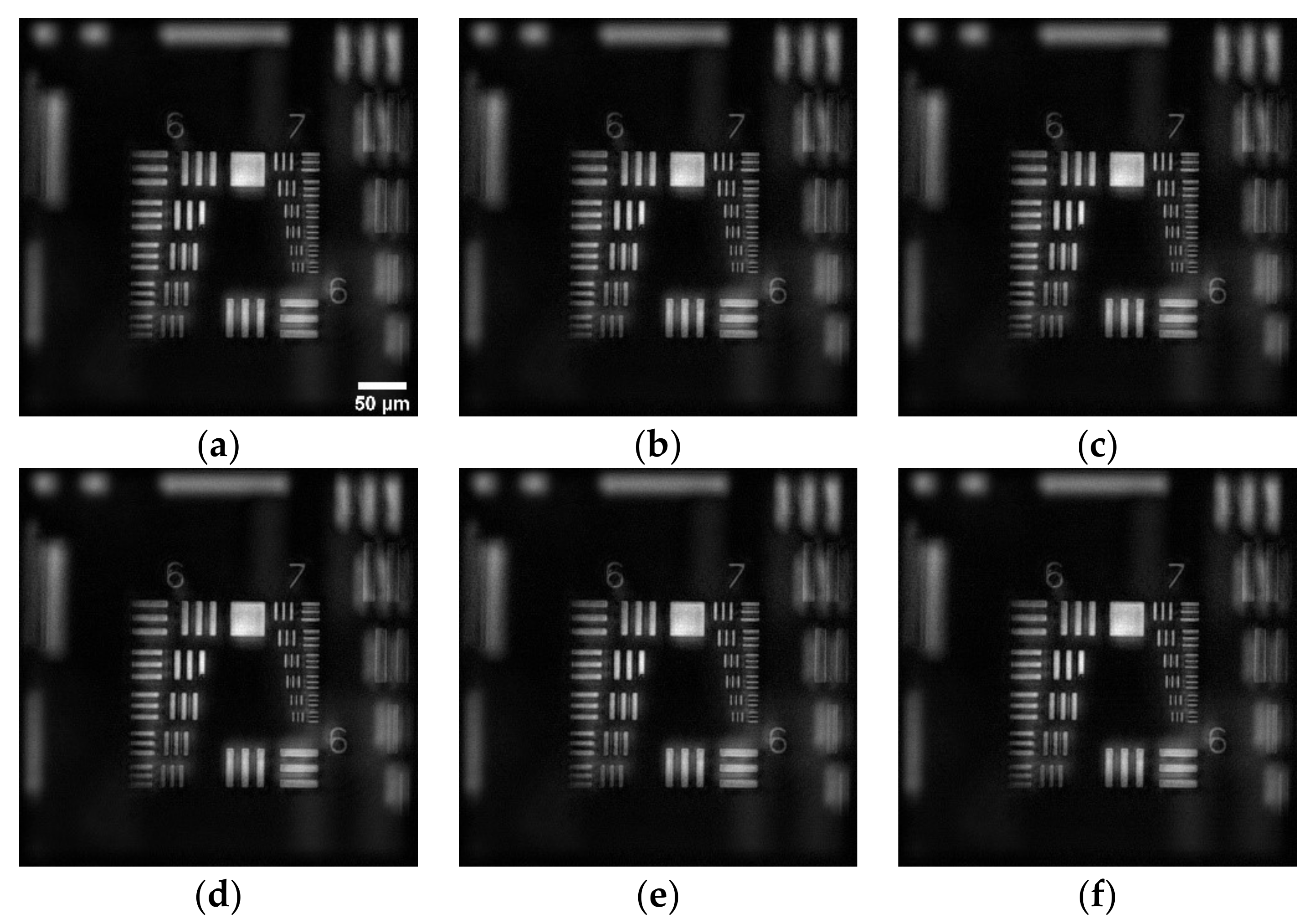
Figure 5a–c shows the reconstructed images obtained using the conventional technique and Figure 5d–f show those obtained using the proposed technique. For the image interpolations, we used the bilinear, bicubic, and Lanczos-3 algorithms with the kernel sizes of 3 × 3, 7 × 7, and 11 × 11, respectively. The peak signal-to-noise ratios (PSNRs) between the images calculated using the conventional and proposed techniques for the bilinear, bicubic, and Lanczos-3 algorithms were 61.2, 61.3, and 62.1 dB, respectively. Thus, the reconstructed images obtained by the two techniques were virtually equivalent.
Table 1 shows a comparison of the calculation time required by the different algorithms. The calculation time was measured separately for object wave generation and diffraction calculations. The results were averages of 100 calculations. The proposed technique effectively reduced the calculation time for the object wave generation. The time required for the object wave generation did not depend on the kernel size of the interpolation. The diffraction calculation time for the proposed technique was slightly longer than that for the conventional technique because the multiplication operations of the Fourier transform of the interpolation kernel were added to the diffraction calculation.
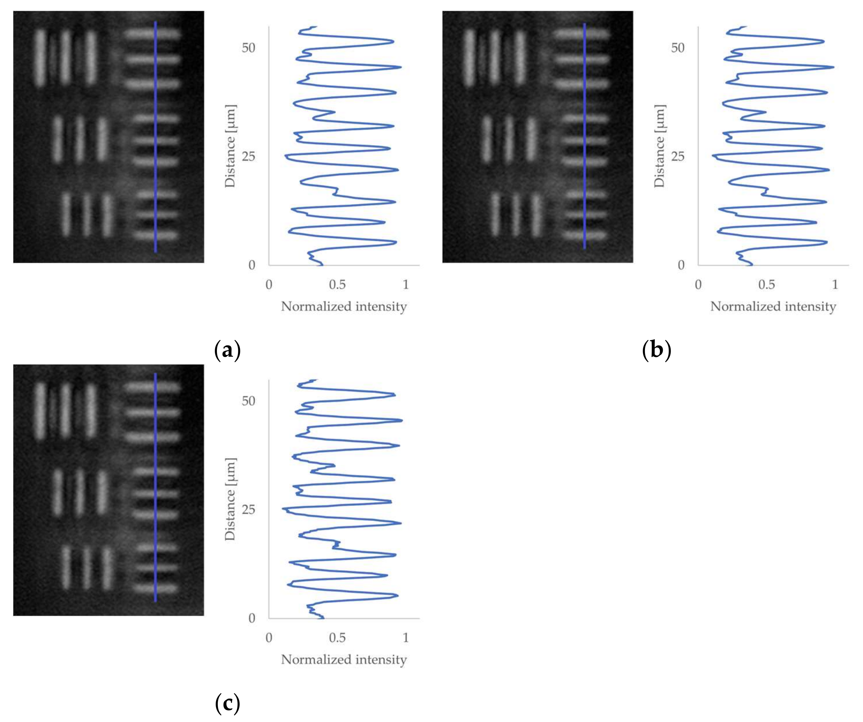
Figure 6 shows the magnified reconstructed images obtained using the proposed technique for comparing the effects of the interpolation algorithms. The highest spatial frequency line group was extracted. From top to bottom, the line spacings were 2.76, 2.46, and 2.19 µm. In [32], the authors reported that in the reconstructed images, the bicubic interpolation produced smaller errors than the bilinear interpolation; however, the calculation time required for the bicubic interpolation was approximately twice as much as that required for the bilinear interpolation. However, in our experiments, no differences were observed in the reconstructed images obtained for the three interpolation algorithms because the line spacings were much larger than the theoretical minimum resolvable distance of the experimental system.

4. Discussion

Our experiment results prove that the proposed technique can effectively reduce the calculation time for parallel phase-shifting digital holography without the degradation of the reconstructed images. The proposed technique is theoretically equivalent to the conventional technique; therefore, we mainly discuss only the calculation time.
As shown in Table 1, the calculation time for the proposed technique was mostly occupied by the diffraction calculation. In this study, the FFT program offered by the fastest Fourier Transform in the West library [34], was used for the diffraction calculation. The use of the graphical processer units (GPUs) for the FFT calculation will substantially reduce the calculation time [35]. Ref. [35] reported that the diffraction calculation time using GPU is approximately 5% of that using CPU. When this time reduction ratio is applied to our results, the total calculation time could be reduced to approximately 40 ms, and image reconstruction with a frame rate of approximately 40 Hz can be achieved. Considering recent advances in GPU technology, video rate (60 Hz) image reconstruction can be achieved in the near future.
The proposed technique replaced the four image interpolation calculations with the two multiplication operations using the fixed complex-number matrices. These multiplication operations can be performed using parallel processing. Therefore, the use of GPUs will also reduce the calculation time for multiplication operations.
In this study, we used the monochrome polarization image sensor. Color polarization image sensors have also been developed and used for incoherent digital holography [27]. When the color image sensor was used, the four extracted images corresponding to the four phase differences become sparse, and the interpolation kernel size increased. Therefore, the proposed technique is more effective for color digital holography that uses color polarization image sensors.

5. Conclusions

In this study, we proposed a fast image reconstruction technique for parallel phase-shifting digital holography. The proposed technique replaces the four image interpolation processes required for the conventional parallel phase-shifting technique with two multiplication operations using fixed complex-number matrices. The proposed technique was experimentally verified using the FINCH system employing the polarization image sensor. The proposed technique increased the calculation speed for the image interpolations by the factors of 6.4, 9.3, and 15.2 for the bilinear, bicubic, and Lanczos-3 interpolation algorithms, respectively. The PSNRs calculated between the images obtained by the conventional and proposed techniques for the bilinear, bicubic, and Lanczos-3 algorithms were 61.2, 61.3, and 62.1 dB, respectively.

Author Contributions

Conceptualization, Y.T. and M.T.; methodology, Y.T., M.T. and T.T.; software, M.T.; validation, T.F. and T.T.; formal analysis, M.T.; investigation, Y.T., M.T. and T.T.; resources, Y.T.; data curation, M.T.; writing—original draft preparation, M.T.; writing—review and editing, Y.T.; visualization, M.T.; supervision, Y.T.; project administration, Y.T.; funding acquisition, Y.T. All authors have read and agreed to the published version of the manuscript.

Funding

This research received no external funding.

Conflicts of Interest

The authors declare no conflict of interest.

References

  1. Nehmetallah, G.; Banerjee, P.P. Applications of digital and analog holography in three-dimensional imaging. Adv. Opt. Photonics 2012, 4, 472–553. [Google Scholar] [CrossRef]
  2. Schilling, B.; Poon, T. Three-dimensional holographic fluorescence microscopy. Opt. Lett. 1997, 22, 1506–1508. [Google Scholar] [CrossRef] [Green Version]
  3. Rosen, J.; Brooker, G. Digital spatially incoherent Fresnel holography. Opt. Lett. 2007, 32, 912–914. [Google Scholar] [CrossRef] [PubMed]
  4. Rosen, J.; Brooker, G. Non-scanning motionless fluorescence three-dimensional holographic microscopy. Nat. Photonics 2008, 2, 190–195. [Google Scholar] [CrossRef]
  5. Brooker, G.; Sigel, N.; Wang, V.; Rosen, J. Optimal resolution in Fresnel incoherent correlation holographic fluorescence microscopy. Opt. Express 2011, 19, 5047–5062. [Google Scholar] [CrossRef] [PubMed] [Green Version]
  6. Rosen, J.; Sigel, N.; Brooker, G. Theoretical and experimental demonstration of resolution beyond the Rayleigh limit by FINCH fluorescence microscopic imaging. Opt. Express 2011, 19, 26249–26268. [Google Scholar] [CrossRef]
  7. Siegel, N.; Lupashin, V.; Storrie, B.; Brooker, G. High-magnification super-resolution FINCH microscopy using birefringent crystal lens interferometers. Nat. Photonics 2016, 10, 802–808. [Google Scholar] [CrossRef] [Green Version]
  8. Jang, C.; Kim, J.; Clark, D.C.; Lee, S.; Lee, B.; Kim, M.K. Holographic fluorescence microscopy with incoherent digital holographic adaptive optics. J. Biomed. Opt. 2015, 20, 111204. [Google Scholar] [CrossRef] [PubMed]
  9. Kim, M.K. Adaptive optics by incoherent digital holography. Opt. Lett. 2012, 37, 2694–2696. [Google Scholar] [CrossRef]
  10. Kim, M.K. Full color natural light holographic camera. Opt. Express 2013, 21, 9636–9642. [Google Scholar] [CrossRef]
  11. Wan, Y.; Man, T.; Wang, D. Incoherent off-axis Fourier triangular color holography. Opt. Express 2014, 22, 8565–8573. [Google Scholar] [CrossRef]
  12. Imbe, M. Radiometric temperature measurement by incoherent digital holography. Appl. Opt. 2018, 58, A82–A89. [Google Scholar] [CrossRef] [PubMed]
  13. Yamaguchi, I.; Zhang, T. Phase-shifting digital holography. Opt. Lett. 1997, 22, 1268–1270. [Google Scholar] [CrossRef] [PubMed]
  14. Takaki, Y.; Kawai, H.; Ohzu, H. Hybrid holographic microscopy free of conjugate and zero-order images. Appl. Opt. 1999, 38, 4990–4996. [Google Scholar] [CrossRef]
  15. Awatsuji, Y.; Sasada, M.; Kubota, T. Parallel quasi-phase-shifting digital holography. Appl. Phys. Lett. 2004, 85, 1069–1071. [Google Scholar] [CrossRef]
  16. Awatsuji, Y.; Tahara, T.; Kaneko, A.; Koyama, T.; Nishio, K.; Ura, S.; Kubota, T.; Matoba, O. Parallel two-step phase-shifting digital holography. Appl. Opt. 2008, 47, D183–D189. [Google Scholar] [CrossRef]
  17. Millerd, J.; Brock, N.; Hayes, J.; Morris, M.; Novak, M.; Wyant, J. Pixelated Phase-Mask Dynamic Interferometer. Proc. SPIE 2004, 5531, 304–314. [Google Scholar]
  18. Sony Semiconductor Solutions Corporation. Available online: https://www.sony-semicon.co.jp/e/products/IS/industry/technology/polarization.html (accessed on 24 August 2021).
  19. Tahara, T.; Kanno, T.; Arai, Y.; Ozawa, T. Single-shot phase-shifting incoherent digital holography. J. Opt. 2017, 19, 065705. [Google Scholar] [CrossRef]
  20. Choi, K.; Joo, K.; Lee, T.; Kim, H.; Yim, J.; Do, H.; Min, S. Compact self-interference incoherent digital holographic camera system with real-time operation. Opt. Express 2019, 4, 4818–4833. [Google Scholar] [CrossRef] [PubMed]
  21. Siegel, N.; Brooker, G. Single shot holographic super-resolution microscopy. Opt. Express 2021, 29, 15953–15958. [Google Scholar] [CrossRef]
  22. Kakue, T.; Itoh, S.; Xia, P.; Tahara, T.; Awatsuji, Y.; Nishio, K.; Ura, S.; Kubota, T.; Matoba, O. Single-shot femtosecond-pulsed phase-shifting digital holography. Opt. Express 2012, 20, 20286–20291. [Google Scholar] [CrossRef] [PubMed]
  23. Kakue, T.; Endo, Y.; Nishitsuji, T.; Shimobaba, T.; Masuda, N.; Ito, T. Digital holographic high-speed 3D imaging for the vibrometry of fast-occurring phenomena. Sci. Rep. 2017, 7, 10413. [Google Scholar] [CrossRef] [PubMed] [Green Version]
  24. Takase, Y.; Shimizu, K.; Machida, S.; Inoue, T.; Nishio, K.; Rajput, S.; Matoba, O.; Xia, P.; Awatsuji, Y. High-speed imaging of the sound field by parallel phase-shifting digital holography. Appl. Opt. 2021, 60, A179–A187. [Google Scholar] [CrossRef]
  25. Tahara, T.; Yonesaka, R.; Yamamoto, S.; Kakue, T.; Xia, P.; Awatsuji, Y.; Nishio, K.; Ura, S.; Kubota, T.; Matoba, O. High-speed three-dimensional microscope for dynamically moving biological objects based on parallel phase-shifting digital holographic microscopy. IEEE J. Sel. Top. Quantum Electron. 2012, 18, 1387–1393. [Google Scholar] [CrossRef]
  26. Inamoto, J.; Fukuda, T.; Inoue, T.; Shimizu, K.; Nishio, K.; Xia, P.; Matoba, O.; Awatsuji, Y. Modularized microscope based on parallel phase-shifting digital holography for imaging of living biospecimens. J. Biomed. Opt. 2020, 25, 123706. [Google Scholar] [CrossRef]
  27. Tahara, T.; Ito, T.; Ichihashi, Y.; Oi, R. Single-shot incoherent color digital holographic microscopy system with static polarization-sensitive optical elements. J. Opt. 2020, 22, 105702. [Google Scholar] [CrossRef]
  28. Tahara, T.; Ishii, A.; Ito, T.; Ichihashi, Y.; Oi, R. Single-shot wavelength-multiplexed digital holography for 3D fluorescent microscopy and other imaging modalities. Appl. Phys. Lett. 2020, 117, 031102. [Google Scholar] [CrossRef]
  29. Goodman, J.W. The Angular Spectrum of Plane Waves. In Introduction to Fourier Optics, 2nd ed.; Director, S.W., Ed.; McGraw-Hill: New York, NY, USA, 1996; pp. 55–61. [Google Scholar]
  30. Matsushima, K.; Shimobaba, T. Band-limited angular spectrum method for numerical simulation of free-space propagation in far and near fields. Opt. Express 2009, 17, 19662–19673. [Google Scholar] [CrossRef] [Green Version]
  31. Yaroslavsky, L. Image resampling and geometrical. In Digital Holography and Digital Image Processing; Springer, LLC: Boston, MA, USA, 2004; pp. 373–410. [Google Scholar]
  32. Xia, P.; Tahara, T.; Kakue, T.; Awatsuji, Y.; Nishio, K.; Ura, S.; Kubota, T.; Matoba, O. Performance comparison of bilinear interpolation, bicubic interpolation, and B-spline interpolation in parallel phase-shifting digital holography. Opt. Rev. 2013, 20, 193–197. [Google Scholar] [CrossRef]
  33. Ramponi, G. Warped distance for space-variant linear image interpolation. IEEE Trans. Image Process. 1999, 8, 629–639. [Google Scholar] [CrossRef]
  34. Frigo, M.; Steven, G.J. FFTW: An adaptive software architecture for the FFT. In Proceedings of the 1998 IEEE International Conference on Acoustics, Speech and Signal Processing, Seattle, WA, USA, 15 May 1998; Volume 3, pp. 1381–1384. [Google Scholar]
  35. Shimobaba, T.; Sato, Y.; Miura, J.; Takenouchi, M.; Ito, T. Real-time digital holographic microscopy using the graphical processing unit. Opt. Express 2008, 16, 11776–11781. [Google Scholar] [CrossRef] [PubMed]
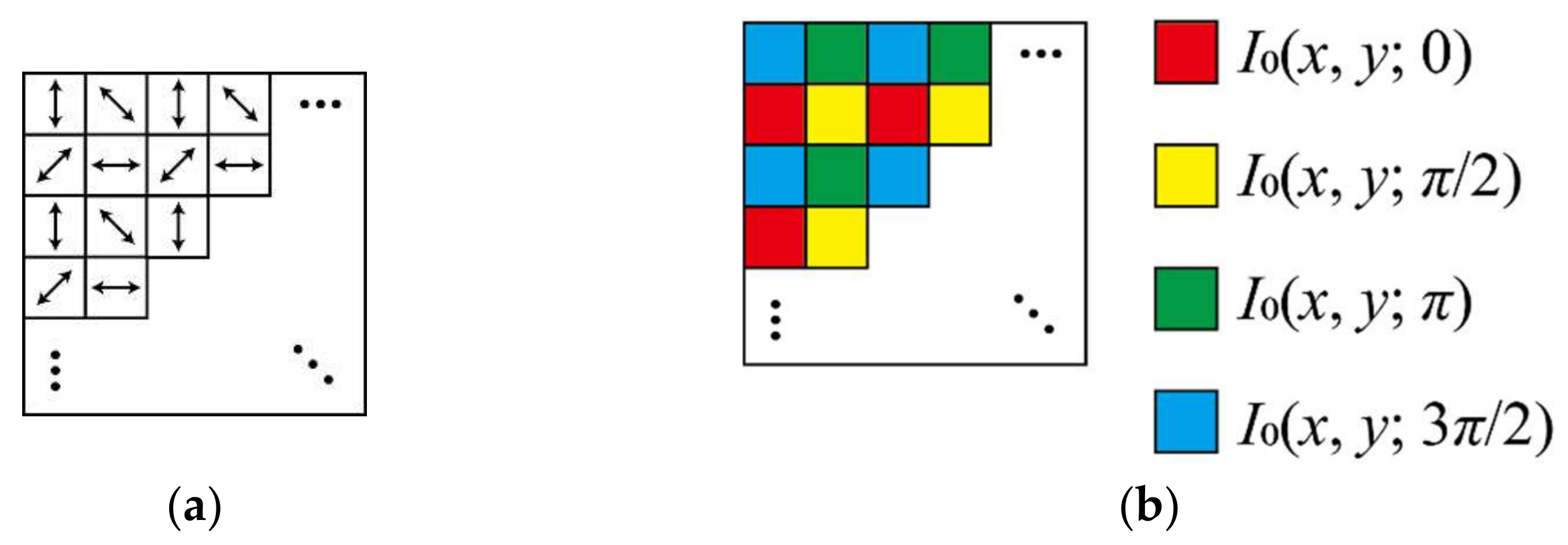
Figure 1. Parallel phase-shifting technique using the polarization image sensor: (a) polarizing axes of micro-polarizers attached to pixels and (b) phase shifts for pixels.
Applsci 11 11343 g001
Figure 2. Conventional calculation procedure for parallel phase-shifting digital holography.
Applsci 11 11343 g002
Figure 3. Proposed calculation procedure for parallel phase-shifting digital holography.
Applsci 11 11343 g003
Figure 4. Experimental system based on Fresnel incoherent correlation holography (FINCH).
Applsci 11 11343 g004
Figure 5. Reconstructed images using (ac) the conventional technique and (df) the proposed technique using the interpolation algorithms (a,d) bilinear, (b,e) bicubic, and (c,f) Lanczos-3.
Applsci 11 11343 g005
Figure 6. Magnified images of the reconstructed images obtained using the proposed technique when the interpolation algorithms were (a) bilinear, (b) bicubic, and (c) Lanczos-3.
Applsci 11 11343 g006
Table 1. Calculation time for the conventional and proposed techniques.
Bilinear (3 × 3 Kernel)Bicubic (7 × 7 Kernel)Lanczos-3 (11 × 11 Kernel)
Conventional
[ms]
Proposed
[ms]
Conventional
[ms]
Proposed
[ms]
Conventional
[ms]
Proposed
[ms]
Object wave
generation
116 ± 518 ± 1167 ± 818 ± 1274 ± 1318 ± 1
Diffraction
calculation
345 ± 14398 ± 17350 ± 14399 ± 17349 ± 15395 ± 17
Total461 ± 19416 ± 18518 ± 22417 ± 18623 ± 28413 ± 18
Publisher’s Note: MDPI stays neutral with regard to jurisdictional claims in published maps and institutional affiliations.