Article

Development of a Hybrid Electric Vehicle Simulation Tool with a Rule-Based Topology

Aramco Fuel Research Center, Aramco Overseas Company B.V., 92500 Rueil-Malmaison, France
Appl. Sci. 2021, 11(23), 11319; https://doi.org/10.3390/app112311319
Submission received: 26 October 2021 / Revised: 19 November 2021 / Accepted: 25 November 2021 / Published: 29 November 2021

Abstract

:
The performance of hybrid electric vehicles (HEVs) greatly depends on the various sub-system components and their architecture, and designers need comprehensive reviews of HEVs before vehicle investigation and manufacturing. Simulations facilitate development of virtual prototypes that make it possible to rapidly see the effects of design modifications, avoiding the need to manufacture multiple expensive physical prototypes. To achieve the required levels of emissions and hardware costs, designers must use control strategies and tools such as computational modeling and optimization. However, most hybrid simulation tools do not share their principles and control logic algorithms in the open literature. With this motivation, the author developed a hybrid simulation tool with a rule-based topology. The major advantage of this tool is enhanced flexibility to choose different control and energy management strategies, enabling the user to explore a wide range of hybrid topologies. The tool provides the user with the ability to modify any sub-system according to one’s own requirements. In addition, the author introduces a simple logic control for a rule-base strategy as an example to show the flexibility of the tool in allowing the adaptation of any logic algorithm by the user. The results match the experimental data quite well. Details regarding modeling principle and control logic are provided for the user’s benefit.

1. Introduction

The hybridization of the powertrain represents an important milestone on the way to CO2-neutral mobility. Nearly all automobile manufacturers have several hybrid concepts in their portfolio. However, the requirements of emissions legislation vary strongly worldwide. In addition, costs, complexity, driving performance and vehicle platform are other important decision criteria for the choice of a suitable hybrid concept. In light of stringent CO2 targets and long-term sustainability, hybrids are considered the most feasible solution in the short and medium term. Hybridization of the drivetrain has been implemented to varying degrees, from 48 V mild hybrids to strong hybrids and to plug-in hybrids, each with increasing degrees of electrification. The governments in various countries are encouraging the adoption of different degrees of electrified cars by mandating stringent emissions standards and providing various incentives and subsidies to buyers.
In the United States, over 4 million pure battery electric vehicles (BEVs) and full hybrid electric vehicles (HEVs) were sold in 2016 [1]. In Europe recently, the rate of growth in the sales of HEVs has also increased, and the main market is for full hybrids followed by plug-in hybrids. The highest sales of hybrid electric vehicles in Japan are in the full hybrid segment, followed by the mild hybrid. Japanese automakers Toyota and Honda are increasing their commitment to producing more hybrid models to meet environmental and fuel security goals. Growth in China’s electric vehicle industry has expanded at an astonishing rate, and the country now has the largest number of BEVs on the road. Within the global economic regions of China, Europe, North America, Japan and Korea, which today account for 86% of the global automotive sales market, China significantly leads in the sale of BEVs. In the future, HEVs and BEVs will continue to dominate the car market, and Japan will no longer be the main market, as growth is expected from Europe and China. The 48 V mild hybrids will be popular in the short term as Audi, VW and many others have adopted them to improve fuel economy. By 2025, approximately one in five new vehicles across the world will be equipped with a 48-Volt drive. Full HEVs will avoid the large trade-off between power and efficiency of pure internal combustion engine (ICE) cars, leading to broader consumer acceptance. Most automakers are planning to produce full HEVs on a large scale. Toyota will continue to rule in the full HEV segment for the foreseeable future. The growth of plug-in HEVs (PHEVs) and BEVs drastically increased from 2016 to 2017, with 73% in China, 39% in Europe, and 27% in the USA. This trend will continue to increase, and the expected sales of PHEVs and BEVs will be more than 2 million in China by 2020.
A scenario from another research team, called the “European original equipment manufacturer (OEM) Scenario”, representing an average value scenario of the European OEMs, was published on the future of powertrain technologies in the new vehicle fleet [2]. BEVs will continuously increase. Their market share will reach approximately 27% in 2035. Plug-in hybrids will maintain their market share constantly at around 10%. In consequence, vehicles that can be externally charged will account for approximately 37% of the overall powertrain share in Europe by 2035. The positive effect of PHEVs regarding CO2 emission reduction potential rests to a great extent upon the current worldwide harmonized light vehicles test cycle (WLTC) test procedure [3,4]. This takes into account the charge depleting and the charge sustain mode. The first defines the CO2 emissions and fuel consumption in that mode, as well as the theoretical electric range. The utility factor can be deduced by the latter. CO2 emission in charge depletion, utility factor, plus CO2 emission in charge sustain mode lead to the weighted CO2 emission relevant for certification. The bigger the battery, and consequently the electric range, the lower the impact of the ICE on the weighted CO2 emission. Nevertheless, highly efficient ICEs are still important, as they guarantee high long-range efficiency when the battery is fully depleted. One issue of the current legislation regarding PHEV is that electricity use under real driving is much lower, and hence more CO2 is emitted. New vehicles have to be equipped with “on-board fuel consumption measurement” since 2020 to determine the fuel consumption and hence the CO2 emission in the field. The results might lead to adaptions to the utility factor if the difference in fuel consumption between certified value and street measurements is too large. If so, the advantage of PHEV with respect to CO2 might decrease in such way that “Not-Off-Vehicle Charging Hybrid Electric Vehicles” (NOVC-HEVs) with smaller batteries and highly efficient ICEs become more attractive in terms of CO2 reduction potential.
The HEV simulation model is very important in the proper design and verification of control strategies for hybrid power plants. The vehicle simulation can be used to address the technical position of different vehicles and to estimate different scenarios of the future trend of the automotive industry. Many researchers have used different hybrid tools like GT-SUITE, AMESIM, AUTONOMIE, GREET, etc., as common vehicle simulators, and most automobile companies have their own software [5,6] to evaluate emerging vehicle technologies and find cost-competitive solutions that minimize fuel consumption and emissions. However, most hybrid simulation tools do not share their principles and control logic algorithms in the open literature. Users have limited access in terms of modifying the control logic and hardware variation. With this motivation, many researchers have developed their own hybrid simulation models with different principles and control logic algorithms [7,8,9,10,11].
Control topologies for HEVs are algorithms that choose the power split between the ICE and electric motors (EMs) of an HEV in order to minimize the fuel consumption and emissions. There have been several proposals for the HEV control strategies in the open literature, e.g., Delprat et al. using heuristics [12], and dynamic programs by Brahma et al. [13] and Rimaux et al. [14]. These approaches require a huge amount of time to obtain solutions and are highly complex. To avoid this significant drawback, a simple control strategy is necessary based on an optimal control theory for different hybrid architectures.
In this paper, the author has developed an HEV simulation tool with such a rule-based topology. The approach described here is based on optimal control knowledge, and it can be easily applied to all types of vehicle simulation arrangements. The major advantage of this tool is enhanced flexibility to choose different control theories and energy management strategies, enabling the user to explore a wide range of hybrid topologies.

2. Materials and Methods

2.1. Overviews of the Simulation Tool

In this paper, a simulation tool developed on MATLAB® and Simulink® is introduced to address HEV technologies. This tool offers increased flexibility to choose different control and energy management strategies, enabling the user to explore a wide range of hybrid topologies. The tool enables the user to modify any sub-system according to their requirements. In the simulation, vehicle speed data are needed, e.g., new European driving cycle (NEDC), WLTC, real driving emissions (RDE), etc., and based on the speed profile, the tool calculates the rotational speed of the wheels, the acceleration, and the total forces using the vehicle dynamics equations. Forces that are taken into consideration are aerodynamic resistance force, rolling friction losses, driving force, and uphill driving force. The rolling resistance depends more on the weight of the vehicle, while the aerodynamic ones depend on the speed. When starting the vehicle, only the resistant forces will act, and then, with the increase in speed, the aerodynamic forces will have a greater impact. In addition to the above-mentioned losses, it is also important to calculate inertia losses in a vehicle, as acceleration or deceleration of rotating components causes significant change in equivalent mass of a car due to inertia.
The total force of the given vehicle is calculated using the formula provided from the following equations:
Total   Force = F Aerodynamic + F Rolling + F Acceleration + F Gradient  
F Aerodynamic = 0.5 ρ C D V 2 A
F rolling = C R m g μ cos θ    
F Acceleration = m v a
F Gradient = m g sin θ
where V is the vehicle speed [m/s], a is the vehicle acceleration [m/s2], ρ is the density of the air (≈1.2 kg/m3), A is the frontal surface area of the vehicle [m2], CR, CD is the drag coefficient, mv is the mass of vehicle + load [kg], g is the gravity acceleration [9.81 m/s2], μ is the friction coefficient [≈0.01], α is the slope [rad].
The calculated total forces are given as input to the ICE model in case of conventional vehicle model. In hybrid vehicle model, additional blocks like EMs and supervisor are also implemented. The supervisor will direct the power demands to ICE or EMs depending on the operating points and the strategy. The control strategy of the supervisor is the most important thing in any model, and system acts/behaves according to the strategy defined by the user. This is nothing but the supervisor in the hybrid powertrain, also known as the brain of the system. The rules of the supervisor are:
  • Continuously meet the driver’s power request based on the accelerator and brake pedal positions and available power in the power sources.
  • Minimize global fuel consumption.
  • Maintain the state of charge (SOC) of the battery between the bounds of the defined SOC.
  • Make sure the battery SOC at the end of the driving cycle reaches the user’s request.
For the control system to switch from one transition to another, certain conditions have to be defined, from which transitions from different states are possible. They include logic functions, and based on these, switching takes place; this is performed for all possible cases in the control system. Once the conditions are defined, they are integrated with the other inputs, where the conditions work by integrating all these the control systems. Figure 1 shows the overview of the HEV simulation tool.
The transmission is a set of elements including gears, shaft, and bearings, which are used to transmit the required power from ICE to wheels of vehicle or EMs. In hybrid vehicles, the transmission can be either a stepped one with a reduced number of gears or a full gear set like a conventional ICE vehicle, depending on the HEV architecture. The purpose of the gearbox is to keep the ICE operating within its optimal operating range for all speeds of the vehicle, from zero to the maximum speed of the vehicle. In the simulation tool, the boundaries of ICE operation are checked to avoid the ICE operating outside of its limits. The initial gearbox used a lookup table, which returned a gear ratio as a function of speed. Hence, it did not account for any maximal torque necessary when accelerating. To solve this issue, a supervisory control was added to the transmission. The supervisor looks at the gear used by the speed lookup table and checks the resulting torque for this gear.
Theoretical values for simulation purposes with the objective of optimizing the gearbox:
T = J   ω ˙
ω = T I C E + T G e n e r a t o r J I C E + J G e n e r a t o r d t    
m f = T I C E ω I C E η I C E L H V
0 T P o w e r D i s t a n c e C y c l e L H V 1000 d t
where T is the torque [Nm], ω ˙ is the angular speed [rad/s], LHV is lower heating value [MJ/kg], mf is fuel mass flow [g/s], ηICE is break efficiency of ICE, TICE is the torque of the ICE [Nm], ωICE is the angular speed of the ICE [rad/s].
Efficiency maps for various sizes of EMs are used from the software advisor in the MATLAB® and Simulink® library, and the closest range size of the EM is selected from the list. Upon picking this from the list, and with the coast down test results, EM models are created. The torque and speed of the vehicle along with the voltage and efficiency map are used to calculate the current required from the EM model. The generator is a device that converts mechanical energy into electrical energy for use in an external circuit. In this HEV simulation tool, it is more specific that the input to the generator is the ICE, which delivers energy, due to the fact being both ICE and generator are coupled on the same shaft with the help of a reduction gear, and both are operating in their most optimal areas. The torque and speed of the ICE, along with the voltage and the efficiency map, are used to calculate the current produced by the generator.
η E M = T V e h   ω V e h V I
η G e n = V I T I C E ω I C E
where TVeh is the torque of the vehicle [Nm], ωVeh is the angular speed of the vehicle [rad/s], V is the voltage of the EM or the generator [V], I is the current required from the EM or the generator [A], TICE is the torque of the ICE [Nm], ωICE is the angular speed of the ICE [rad/s].
Regarding the battery model, a generic battery model is used in the HEV simulation tool from the MATLAB® and Simulink® library [15,16]. Battery models based on equivalent circuits are preferred for system-level development and control applications due to their relative simplicity. The battery block implements a generic dynamic model that represents most popular types of rechargeable batteries. The model parameters are derived from the discharge characteristics. The discharging and charging characteristics are assumed to be the same. The transfer function represents the hysteresis phenomenon for the lead-acid, nickel-cadmium (Ni-CD), nickel-metal hydride (NiMH) and the lithium-ion (Li-ion) batteries during the charge and discharge cycles. The Li-ion battery model is mainly used in the simulation tool. To represent the temperature effects of the lithium-ion (Li-ion) battery type, an additional discharge curve at ambient temperature, which is different from the nominal temperature, and the thermal response parameters are required. A battery pack model which contains an equivalent circuit cell model, a lumped capacitance battery thermal model, and battery management system (BMS) controls is implemented in the simulation. A lithium-ion battery cell is modeled by using a two time constant equivalent circuit cell mode. The SOC (in %) is calculated by the formula given below.
SOC = 100 1 1 Q 0 t i ( t ) d t

2.2. Control Strategies of the Simulation

2.2.1. HEV Operating Modes

The control system/supervisor will determine various requests to decide the operating mode of the hybrid vehicle, and these parameters are the key in the control system:
  • Selecting the power source to deliver power based on the demand from the driving cycle:
    -
    Power demand from the EM.
    -
    Torque demand from the ICE.
  • Speed/acceleration of the vehicle.
  • SOC of the battery.
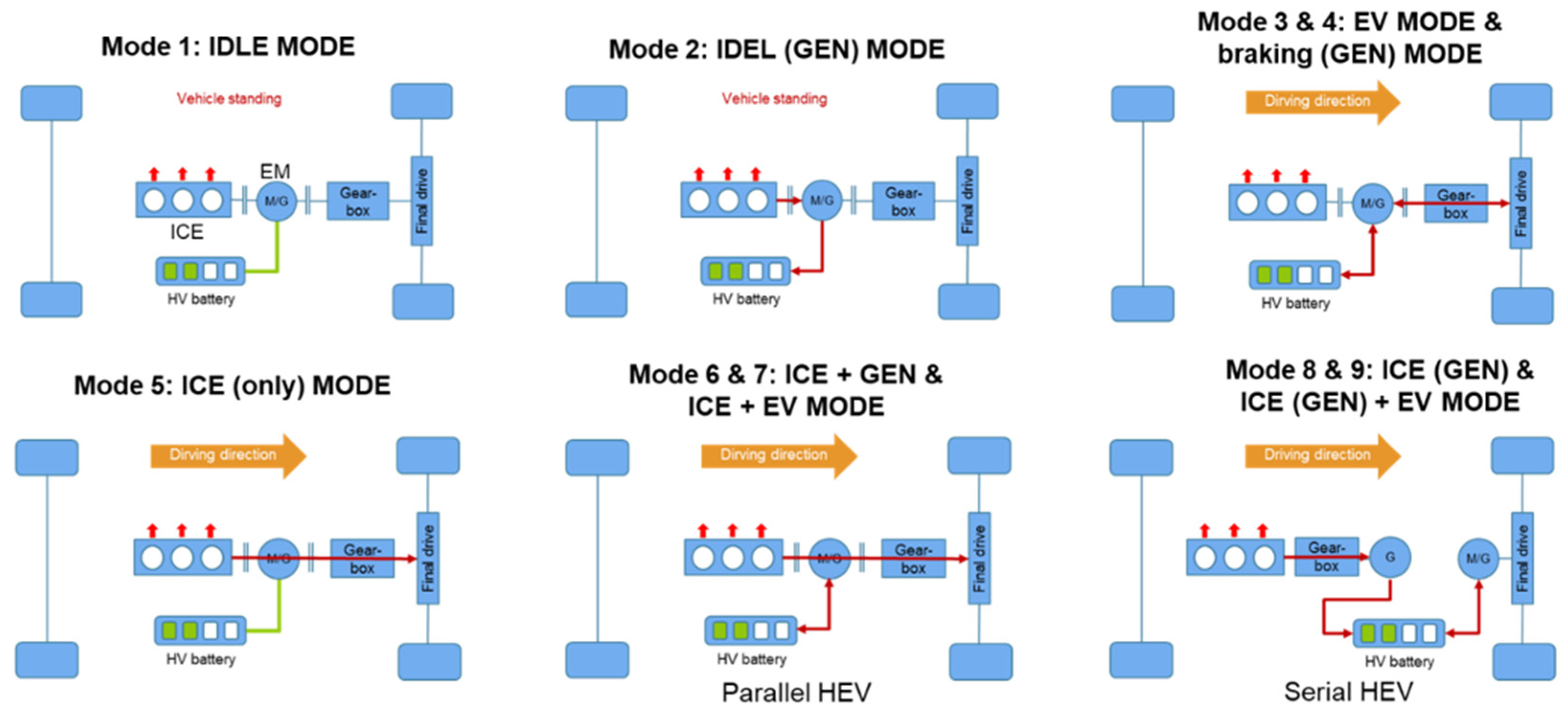
In the control strategy, the tool considers these control parameters as inputs for the system to move for one transition to another over the driving cycle power demand. These values can be modified accordingly to achieve the best results. A rule-based control topology is introduced in this paper, and it determines the transition of variable driving modes on the HEV simulation. The output of the supervisor block is the active drive mode of the vehicle during the given driving cycle. The supervisor is the master controller, and it controls the other subcomponents of the vehicle, such as ICE, power devices, transmission, etc. In total, nine different states are available in the simulation, as shown in Figure 2.
IDLE mode is the stationary position of the vehicle. This state describes the behavior of the vehicle when not moving, meaning the ICE with generator and the EMs, the two power sources, are at rest. The entire system is at rest, with no generation of power. ICE (GEN) mode is also the stationary position of vehicle. This state describes the behavior of the vehicle when not moving, but the ICE with generator is switched on to charge the battery when the SOC of the battery is depleted. Meanwhile, the electrical machine remains switched off or in a resting position. This state remains active until one of two conditions is met: until the battery reaches a nominal SOC, or until there is a power request from the driving cycle. EV (short for Electric Vehicle) mode is the behavior of the vehicle when there is a power demand from the driving cycle, so the vehicle launches from a state of rest through the power supplied by the battery to the electrical machine, while the ICE and generator remain in the state of rest. This state is only available in HEV or BEV, and is called e-drive mode or battery-only mode; this is the state where only power from a battery is supplied to the EM. When the EM is used as a generator to recuperate this negative power available, and this in turn is used to charge the battery, this is called Braking (GEN) mode. This state also describes the behavior of the vehicle when decelerating. If the braking power is not sufficient to stop the vehicle, it will additionally use mechanical brakes to stop. In ICE + GEN mode and ICE + EM mode cases, the ICE with an EM is mechanically coupled to the wheels to provide power to the vehicle in parallel hybrids. In this state, the excess power generated by the ICE is used to charge the battery (ICE + GEN mode), and the extra power needed is supplied by the battery through EM (ICE + EV mode), in case the power request from the driving cycle is higher than the power from ICE. In serial hybrids, ICE (GEN) mode is active when the power request from the driving cycle is higher than that possible to deliver by battery. Since ICE and the generator are coupled on the same shaft, the power from the generator is delivered to the electrical machine to drive the vehicle. Both the ICE and the generator are run in their most efficient areas. ICE (GEN) + EV mode is the state when the power request from the driving cycle is very high compared to that of which the individual power sources are capable; therefore, a combination of the power sources is used to drive the cycle. The maximum power by the ICE (GEN) is used, and the remaining power that is needed is supplied from the battery. ICE (only) mode is the state in which the vehicle runs like a conventional ICE vehicle.
Depending on the hybrid architectures, the used hybrid modes can be represented by 6 or 7 states among the 9 total modes described above. For example, 7 modes (1−7) are used in parallel hybrids, 6 modes (1−4, 8 and 9) are for serial hybrids, and serial/parallel (2 mode) hybrids use 7 modes (1−4, 5, 6 and 9).

2.2.2. Rule-Based Control Strategies

Rule-based control topologies are introduced in this section for serial, parallel and serial/parallel hybrids. Serial hybrids allow a complete decoupling of the ICE from the powertrain, which makes it easier to implement efficiency-increasing ICE measures that react sensitively to transient behavior. Such hybrid concepts show a high degree of freedom regarding the charging process of the battery. It can easily be charged at vehicle stop and at low vehicle speeds, for instance. An additional positive effect of the serial hybrid powertrain is its electrical driving experience. In contrast, there is the long efficiency chain from the ICE to the wheel. The overall losses of this mechanical/electrical path cannot be neglected, although the ICE can be operated at optimum efficiency. This becomes particularly clear at high vehicle speeds, as the high speeds of the EMs cause the efficiency of the machines to drop sharply. In comparison, a parallel concept has a significantly lower degree of freedom in the charging process of the battery. Likewise, the customer’s desired electric driving experience cannot be achieved in every driving situation. Although the ICE cannot be operated with optimum efficiency at every point due to the mechanical coupling, this can be approximated by a large number of gear stages combined with an operating point shift by charging/discharging the battery while driving. The efficiency chain from the ICE to the wheel is significantly shorter compared to the serial concept. Part of the mechanical power generated by the ICE is always fed directly to the output, bypassing the electrical path. A fuel consumption advantage over the serial approach can be expected. In case of serial/parallel hybrids, it is able to combine the advantages of both approaches. Due to the dynamical coupling and structural complexity, the serial/parallel hybrid driving system possesses multiple working modes to adapt to different driving conditions. As an example, in this paper, the author introduces a simple logic control for rule-base strategies in the following sections. This is to show the flexibility of the tool in adapting any logic algorithm by the user.
  • Parallel hybrid topology
Among 9 different modes (the different modes described in 
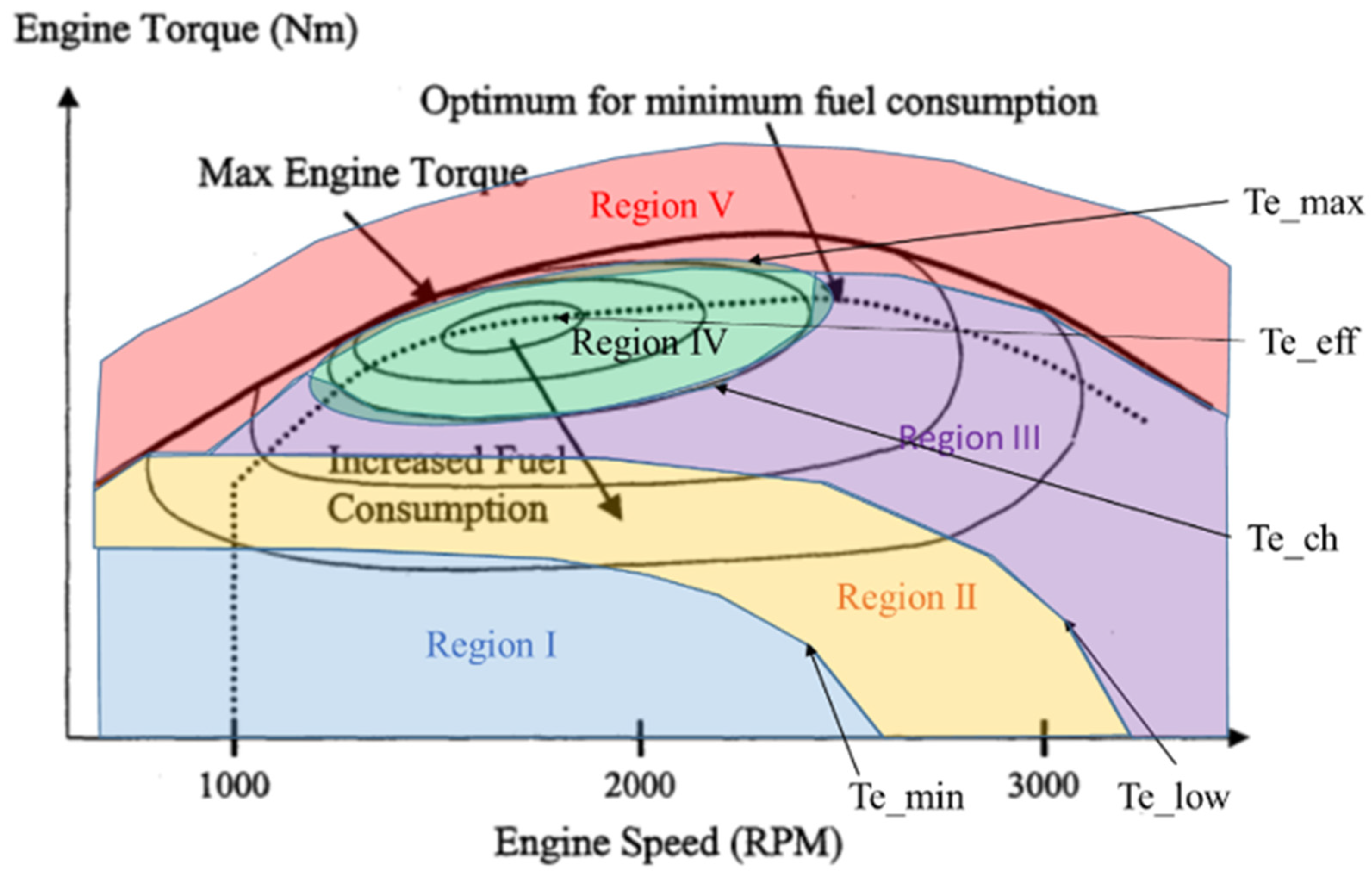
Section 2.2.1), 7 different operating modes are selected for parallel hybrids in the HEV simulation tool, so it is necessary to divide the different states into operating ranges, because the torque demand from the ICE will be a major control parameter, since the ICE is directly connected to the wheels in parallel HEVs. To clarify the system of mode switching, a rule-based control topology for the parallel hybrids is proposed for optimal system efficiency. The operation regions are divided according to the test data of the engine [7], as shown in Figure 3. As shown in this figure, the line “Te_min” is the very low torque curve, with a relatively poor efficiency of ICE, “Te_low” is the minimum torque, and “Te_ch” is the limit of torque of charging mode. Region IV (in green) is the area with minimum fuel consumption, based on the example of test data of an engine. The dash line “Te_eff” represents the optimum area for minimum fuel consumption at a given engine speed and “Te_max” is the expected limit of engine torque in this hybrid simulation, which is close to the solid line for full loads of the engine. Above the line, a combination of the power sources, ICE and EMs, is required to carry out very high power requests. Based on the different regions, the operating system is divided into five parts, which are: e-driving mode (Region I), e-driving or engine driving mode (Region II), charging mode (Region III), engine driving mode (Region IV), and engine and EM hybrid mode (Region V). To formulate the control strategy of the parallel hybrids, two other parameters are considered, which are battery SOC and vehicle speed. The vehicle speed is just used to realize the IDEL mode, and the SOC is the other main parameter for the control logic. As a control parameter, the SOC is divided into five levels: “SOC_min” is the minimum level of SOC for the battery function, “SOC_low” is a variable level to represent the relatively low level of SOC based on the driver’s opinion for the optimization. “SOC_initial” is the SOC at the beginning of the simulation, and “SOC_high” is again a variable SOC representing a high level of SOC, which can set by the driver. “SOC_max” is the maximum SOC of the given battery.
In principle, the drivers are able to design their own control topology by themselves in the HEV simulation tool (e.g., state-flow box or Fuzzy logic toolbox). According to Figure 3, the judgment conditions of each working state are set, and the target torque of the motor and engine can be varied upon driver request. Region I is the economic zone, in which EV mode is mostly used to minimize fuel consumption. The engine runs only when the low limitation of SOC is reached. Region II is the area where the e-driving mode is slightly reduced, depending on the SOC, and the engine runs to charge the battery when the SOC is lower than SOC_low. In Region III, the engine is operated mainly near the optimum point in the minimum fuel consumption area to manage the required torque from the wheel while the battery is charged. The EV mode can only be handled when the SOC is above SOC_high in the region. In Region IV, the vehicle runs mostly like a conventional ICE vehicle, with the highest efficiency from the engine map. The engine cannot achieve the very high torque requirements from the wheels, like in Region V, and thus the EM and the ICE are coupled to deliver very high torque in hybrid mode if the SOC is sufficient. The engine runs with the highest torque to minimize the drop of SOC in this region. In all cases, the vehicle is basically not in a stationary position, and from the figure, the parameters in black (e.g., SOC_min, SOC_initial, SOC_max) are a fixed value, while the red parameters (e.g., SOC_low, SOC_high, Te_min, Te_low, Te_ch, etc.) are varied for the optimization process (Section 3).
2.
Serial hybrid topology
In the serial hybrids, the power demand of the EM will be a main parameter, since the EM is directly connected, and the SOC is the variable that determines the power from the EM and the ICE for hybrids. In a similar way to parallel hybrids, the different operating modes of the serial hybrids (six modes in the serial hybrids in Section 2.2.1) are used for the control topology, with different modes being selected in different regions. The vehicle speed is just used to realize the IDEL, i.e., in all the cases, the vehicle speed is not in the stationary position. The SOC is divided into five levels, like the parallel hybrids, i.e., SOC_min, SOC_low, SOC_initial, SOC_high and SOC_max, and SOC_low and SOC_high are again the flexible values for the optimization process. According to the power demand of the wheels, the operation modes have been divided by the different levels of power from the EMs, and it also depends on the number of engine OPs from single OP to multiple OPs. 
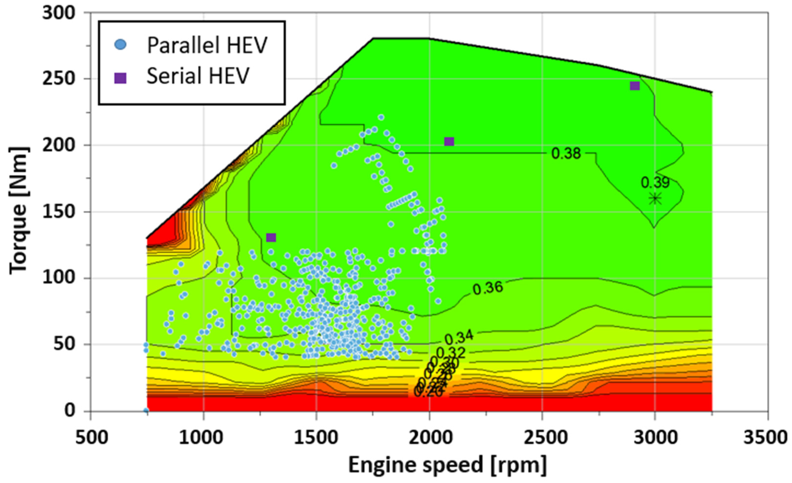
Figure 4 shows examples of the engine OPs for serial hybrids with single OP (the symbol with the red star) and multiple OPs (the symbols with blue stars).
The control strategy for a single OP for serial hybrids is relatively simple. As long as the SOC is above the threshold value, depending on the power demand of the EM, the ICE will be at rest. The ICE with generator is switched on to charge the battery when the SOC of the battery is depleted. Both the ICE and generator run in their most efficient areas. The serial hybrids with a single engine OP are ideal for serial hybrids with large battery sizes, like range-extender hybrids. Mostly, EV mode is used until “Pm_eff” (Pm_eff is the calculated power of the engine at the OP to transfer the power demanded by the EM), while the engine runs to charge the battery according to the SOC. In case of high power demand from the EM, the engine and EM run mostly together in hybrid mode to avoid high battery discharge in this region.
In the case of the traditional serial hybrid topology with multiple engine OPs, three engine OPs (blue symbols in Figure 5, for example) are used in the case of the serial hybrid; OP2 is the most efficient operating condition in the given engine map, and OP1 is a relatively highly efficient point with low torque and speed. OP3 is the maximum power from the engine. The ICE power command depends on the threshold value of SOC at different levels of total power demand of the EMs. The power demands of the EMs is divided across the range from “Pm_min” to “Pm_OP3”. “Pm_min”, “Pm_low” and “Pm_high” are variable values based on driver inputs, and “Pm_OP1”, “Pm_OP2” and “Pm_OP3” are calculated values that determine the combination of torque and speed of the ICE at the OPs for the generated power demand. The EV mode is mostly used to minimize the fuel consumption below Pm_OP1 (e.g., SOC_min, SOC_low or SOC_initial, depending on the power demand of the EM), and the ICE runs only to charge the battery when the SOC is lower than the threshold values set as low limitations. Above Pm_OP1, the EV mode will be limited only to cases where the SOC is high. When the SOC is below the threshold, the combination of the power sources (ICE and EM) will be used, and the operating regions of the ICE (OP1 or OP2) and the operating modes (ICE (GEN) + EV mode or ICE (GEN) mode) will be varied depending on the SOC. Above Pm_OP2, the system mostly runs in hybrid mode and charging mode, with maximum power coming from the ICE to minimize the discharge of battery, and very limited EV mode. The objective of the topology with multiple OPs is to keep the ICE operation in the sweet spot of relatively low fuel consumption, and further increase in demand essentially keeps the system operating in hybrid mode to maintain a reasonable level of SOC. The present study uses a 1-speed transmission concept, as less emphasis is placed on the vehicle’s ability to climb and accelerate. The main lever here is the most cost-effective concept with minimal fuel consumption. The use of a higher number of gears is also possible in this simulation tool.
The operating parameters can be controlled by the topology using a state-flow or a Fuzzy logic tool in the simulation. The control strategy of hybrids decides on the instantaneous power request from the different energy sources while respecting numerous constraints. For this reason, the combination of the parameters and the energy management strategies is very important for the HEV optimization for energy consumption. In this simulation, the Fuzzy logic controller is proposed. In case of a serial hybrid model, for example, the power demand, SOC and vehicle speed are generally used as the control parameters. The required power for EMs is generated by a combination of a generator for an ICE and an EM. They are very simple, conceptually, consisting of an input stage, a processing stage and an output stage. The input stage maps the parameters to the appropriate membership functions and the truth values. The processing stage invokes each appropriate rule and generates results for each, then combines the results of the rules. Finally, the output stage converts the combined results back into a specific control output value. The advantage of the Fuzzy logic is helping the user to view systematic validation of each interaction. The result of simulation shows the excellent effect of the optimal control strategy to share the required power between the ICE and the electric motor. Through the simulation, it can be proved that the fuzzy logic controller is useful for improving driving performance, and the Fuzzy logic technique is suitable for hybrid electric vehicles [17].
3.
Serial/parallel hybrid topology
In multi-configuration hybrids, clutches or power-split gear sets make it possible to switch from one configuration to another (i.e., between serial and parallel systems). The serial/parallel configuration has a similar control topology to the one described before, for serial hybrids. The difference arises from its flexibility, which allows the mechanical connection of the ICE to the wheels in parallel hybrid mode or the combination of the power sources (the EM and the ICE with a generator) as in serial hybrid mode. The increased flexibility allows a combination of the advantages of each hybrid architecture. All nine operating modes (Section 2.2.1) are able to be used in the serial/parallel hybrid topology. Here, the vehicle acts as a serial hybrid at low speeds and as a parallel hybrid for highway cruising. At low speed and torque (below Pm_OP1, like serial hybrid), the vehicle works either in serial mode or in pure electric (EV) mode, and the status of the ICE is determined by the SOC values. At medium power demand (between Pm_OP1 and Pm_OP2, like for the serial hybrid), the serial and parallel systems are used depending on SOC. With a further increase in the power demand of wheels (above Pm_OP2, like serial hybrid), the parallel system will mainly be used. In this configuration, all the machines can directly act on the gearbox input shaft to meet the torque demand of the vehicle. The energy management determines what fraction of torque is generated by the EM and the ICE.

2.3. Optimization Process of the HEV Simulation

Even though the control topology was developed using a rule-based approach based on certain parameters such as speed and torque, power demand and battery, the optimization of these parameters is necessary in order to select ideal inputs to achieve some significant results, for example, the possible benefits with respect to fuel consumption. The simulation tool was used to perform the optimization process using the Fuzzy logic tool and the global searching (GS) algorithm.

2.3.1. The GS Algorithm

To optimize the results, the inputs of all parameters for the control topology need to be defined by an optimization tool to identify the optimal setup regarding the efficiency of the simulation. In general, the equivalent consumption minimization strategy (ECMS) forms the basis of these approaches in hybrid simulation tools. With this strategy, the optimal power distribution between the electrical and the mechanical path of the powertrain can be determined. The ECMS is not a very flexible approach; it cannot be easily combined with the driver’s control strategies and driving conditions. For this reason, the optimization toolboxes of MATLAB® contain various solvers to find optimal solutions to continuous and discrete problems, perform trade-off analyses, and incorporate optimization methods into algorithms and applications. In this simulation tool, the GS algorithm toolbox is selected. The optimization toolbox allows the user to perform design optimization tasks, including parameter estimation, component selection, and parameter tuning. It helps to find optimal solutions in applications such as portfolio optimization, resource allocation, and production planning and scheduling. The process of the optimization tool is in Appendix A. The optimization approach is a look forward strategy to define an optimal parameter by the minimization of the difference between a reference and the current state in horizon time. The features of the optimization procedure are used in the process. By means of the automated process, the lowest fuel consumption is determined with a balanced SOC. The function of the power split for the target of minimization of fuel consumption is as follows (Equation (13)):
m ˙ f u e l   t a r g e t = m ˙ f u e l + s ( t ) / L H V · η E M · η b a t t e r y · η g e n e r a t o r · η g e a r
where m ˙ f u e l is fuel path by engine and s(t) is correction factor.
This function is used to determine the optimal power split between the engine and electric devices at every time step. Figure 5 shows an example of the optimization process in a parallel HEV by changing the hardware in NEDC. The power requirement is calculated on the basis of the speed profile (green in Figure 5) based on the reference (black line) before modifying the hardware (in this case, enlarging the battery size), and the power is divided between ICE and electric devices via trial and error, rewarding the optimal sub-strategies (SOC in blue in Figure 5), and then the optimal SOC strategy for the minimum fuel consumption on the driving cycle is defined.

2.3.2. Energy Management and Losses

An HEV is driven with multiple connections between components, e.g., the ICE in connection with the transmission or the generator, the battery package provides power via EMs, and they can also be combined with each other using a complex transmission. Reducing the fuel consumption of an HEV is equivalent to improving the efficiencies of the HEV components, especially with a good energy management system, i.e., one that minimizes energy losses. The ICE should be run at the best efficiency OP for high HEV efficiency. However, operating the ICE at minimum fuel consumption with a high ICE efficiency is not the best case every time. The energy management of all components is also a very important issue for the HEV system. In this simulation, the energy management is regulated by adjusting the efficiency of components like the ICE, the generator, the gears, and the EMs. When the ICE is operated in the high efficiency region, there will be energy losses from the EM and the battery. For this reason, if the power requirement of the driving cycle is lower than the best efficiency line of the ICE, the remaining energy is stored via the generator in the battery. Otherwise, if the power demand is higher than the engine’s highest torque, the battery provides the remainder of the energy needed. In that case, there will be extra energy losses from the EM and the battery. These energy management strategies will differ depending on HEV architectures and components. When the ICE is connected mechanically to the wheel like in parallel hybrids, the energy loss is much lower compared to serial hybrids. Thus, when the ICE drives the wheels directly, there is an area near the engine’s best efficiency point in which the total ICE efficiency is higher than that obtained by the regulation of maximum efficiency [18]. In the application of the simulation, the conventional transmission of a non HEV is used to regulate the working point as close as possible to the best efficiency line of the engine at a given power. Regarding the analysis of the energy losses, the simulation considers the energy balance for each component, as shown in an example in Figure 6. The red arrows represent the energy losses, the mechanical energy transfer is indicated in blue, and electrical energies are represented with orange.

3. Results

3.1. HEV Simulation Results

In this section, some simulation results are shown to explain the processes of the hybrid simulation, as well as the usage of the simulation tool in different studies. The vehicle considered in this section is a typical medium-sized European C-segment passenger car, which has the highest demand among the vehicle categories in Europe. The vehicle parameters used in this simulation were a vehicle weight of 1500 kg without battery, a cw-value of 0.3, a frontal area of 2.28 m2, A, and a dynamic wheel radius of 0.230 m. The weight of the battery was considered to be 14.4 kg/kWh. During the simulation, the individual models for different components were created first to check if they produced reliable results, and then these blocks were integrated together to complete the full model. This means that the hybrid configurations (e.g., EMs, gear set, ICE, battery, etc.) were selected randomly, and the components and control logic were updated based on the results of the simulation with the GS optimization. In this optimization process, simulation results are presented to evaluate complexity, emissions, and fuel consumptions of the hybrid simulation. Regarding the time required by the simulation, a single point of the hybrid simulation on a driving cycle takes less than 5 s of calculation. For example, the GS optimization for variations of parameters (e.g., power demands, SOCs, gear ratios, target parameters like CO2, etc.) will take less than 3 days if the user manages some relevant boundary values for the parameters. This means that the user needs about 3 days to perform a simulation for a hybrid architecture with given components.

3.1.1. Validation of the Vehicle Model

The sole purpose of validation was to observe whether the control system was capable of and feasible for integation with any given data and specifications. This is a way of checking whether the control system was reliable before beginning the actual simulations, so that if there were any need to perform modifications, these could be done at the earlier stages, rectifying the issue, instead of proceeding with a faulty control system. For this stage, the user is able to validate the model in comparison to their own experimental test results and, for example, it can be used for the development of simulations that can be used for making engineering predictions on the basis of quantified confidence. This specification can be used in the simulation model to further observe results such as the SOC of the battery and fuel consumption. Figure 7 shows an example of the validation of torque demands, instantaneous CO2, and accumulated CO2 on cold WLTC by means of the simulation compared to chassis dynamometer test data in the case of a vehicle test without hybridization. The ICE is 1.6 L modern compression ignition (CI) engine with a variable-geometry turbocharger (VGT) system. According to the comparison, the trends of simulated engine torque and CO2 emissions are in good agreement with those of the experimental results. The role of a vehicle’s transmission model is to adapt the traction performance of the ICE to the road load and acceleration demand of the driver. The gear position was estimated using driver pedal acceleration and transmission/vehicle speed. The gear selection by the model simulation was in excellent agreement with the experimental results. From the figure, it can be observed that the energy management and the control system work well, as the simulation results show a similar trend for both the torque demand and CO2, proving that it is reliable and can be adapted to any data, providing significant results.

3.1.2. Optimization of Elements

After the validation of the vehicle model, a method for optimization is required for hybrid systems to improve their energy consumption or driving performance on the basis of the driver’s requests. The role of the optimization method is not only to find optimal selections and boundaries of the working modes, but also to enable the user to have an idea of the optimal design of hybrid configurations and components under the given driving conditions. Through the combination of the hybrid with an ICE, the engine and the EMs mainly run at the maximum feasible efficiency operating point within the driving cycle. The user has to consider the power limit of components and the SOC of the battery. For this reason, the selection of the number of gears and the type of transmission play a very important role. As described in Section 2.3.1, the GS algorithm is used as the optimization method because the traditional control strategies and optimization tools used in the HEV simulation are a black box. The hybrid simulation is able to perform optimization tasks to determine the maximum potential of a given architecture, and then, on the basis of the simulation results, the user is able to start the next initial optimization step with backward optimized result for parameter estimation, component selection and parameter tuning. By repeating the simulation steps, the GS algorithm is able to determine the best solution for the parameters by defining the recursion equation. This can be used to find optimal solutions in applications such as portfolio optimization, resource allocation, and production planning and scheduling. For this reason, the GS algorithm is used to improve the overall performance by adapting rule-based topologies (Appendix A).
Figure 8 shows the WLTC operating point distribution of the engine (1.6 L CI engine) for a parallel hybrid and a serial hybrid. From the first simulation, the average ICE efficiency was about 33%, which is a relatively high efficiency compared to conventional vehicles without hybridization. However, the efficiency can be further improved by shifting the operating conditions in the optimization process, as the area of high engine efficiency is located at high engine load for the ICE. By adapting the gear ratios and the mode switching (the optimization function of the power split), a mean engine efficiency about 2% points higher was achieved using the GS optimization process. The target of minimizing fuel consumption was the main request for GS optimization, while also maintaining the same SOC between the SOC_initial and SOC_final during the driving cycle. In a similar way, the EMs and other components can be also optimized by means of this process.
The selection of components is important for the hybrid model, because the operation points have to be selected with respect to the limits of components and the size of materials, which are linked to the cost of the vehicle. The simulation can be used for the adaptation of such hybrid components, e.g., EMs, generators, batteries, and gear sets. From the first simulation, the mean efficiency of the EM (80 kW) for a serial hybrid on WLTC was about 87.8% (83.4% with an inverter). In the optimization process, the adapted axle drive ratio was checked, including the possibility of changing the transmission ratio. On the basis of this process, the mean efficiency of the EM was able to reach up to 90% by adapting the efficiencies required for WLTC. The improvement is mainly a result of shifting to the high-efficiency area by means of the adaptation of the components and the gear set. This value could be even higher by adapting new components and using exemplary inverters with higher efficiency traction. Figure 9 shows the final energy-weighted operating points of the EMs (80 kW) for a serial hybrid on WLTC. By means of the optimization process, the mean efficiencies of the EM were able to reach more than 92%. The selected gear ratio for the hybrids matched those of the EM when operated within WLTC close to the best efficiency area with constant power demand (e.g., the dashed line is constantly 45 kW), and the velocity of the EM for the serial hybrid was set close to 160 km/h as the maximum speed of the EM (red spot in Figure 9). This is a good example of the use of practical study for the selection of hybrid components in order to maximize the potential of the hybrid concept. In the case of a parallel hybrid, the improvement is mainly a result of the optimized efficiency of the EM, as an eight-gear transmission maintained the operating points at best efficiency, although the overall efficiency (about 83% at the wheel) of the EM was worse due to the transmission losses compared to the hybrid with the serial hybrid option.

3.1.3. Final Results of the HEV Simulation

In the final stage, the HEV simulation was run to calculate the pollutants, the SOC, the CO2 emission and fuel consumption using the selected components under a given driving condition.
Figure 10 shows, as an example, the results for the final selection of mode switching for a serial hybrid on WLTC (the different colors represent different modes). For the control system to switch from one transition to another, it had to be possible to define certain conditions with respect to different states, and the logic functions involved were based on the optimal strategy from the GS algorithm. Once the conditions were defined, they were integrated with the other inputs related to the conditions, in order for all these control systems to work together. In this case, the battery capacity was 8.8 kWh, the e-driving range was up to 50 km, and 100 kW of EM and 50 kW of the generator for the serial hybrid. As can be seen, the EV mode (in green) was mainly selected to minimize fuel consumption at low vehicle speeds (early stage of WLTC), and hybrid modes (ICE + GEN mode or ICE + GEN + EV mode) were used on the basis of the SOC values.
Figure 11 shows examples of results of vehicle speed, EM speed, EM torque, EM power, and the SOC of serial, parallel and serial/parallel hybrid configurations on WLTC. The battery capacity was 8.8 kWh, which corresponded to an e-driving range up to 50 km and 50 kW of EM for parallel and 100 kW of EM and 50 kW of generator for serial and serial/parallel hybrids.
In general, the EMs for serial and serial/parallel hybrids are operated at higher speed with higher efficiency compared to parallel hybrids. However, the EMs for serial hybrids are always in operation during the power demand of the driving cycle. Each hybrid configuration has different optimization methods. In serial hybrids, the EM and ICE with a generator operate independently of each other, with each operating in its most efficient range. The electric driving mode is mostly used at low vehicle speeds to minimize fuel consumption, and the ICE status is determined on the basis of the SOC values. In parallel hybridization, ICE and EM are used in parallel, with mechanical coupling bein used to add the torque provided by both sources. Another drawback will be the necessity of a complex mechanical device used to sum the power coming from the ICE and from the EM. The serial/parallel architecture combines the advantages of both aforementioned architectures. This configuration is more complicated, because it involves additional components like mechanical links, and controls and an additional generator. The power splitting device divides the power provided by the ICE into mechanical and electrical paths through a transmission or a planetary gear set. The flexibility of control strategy is a benefit of the configuration, as the ICE and the EM are able to run at their maximum capacity by adapting to the driving conditions.
Through the combination of the ICE and the EMs in the HEV simulation, all three hybrid configurations are able to reduce CO2 by up to 30% on WLTC compared to non-hybrid vehicles. The main benefit of hybrids is that the ICE is able to achieve its best efficiency near full load, making operation in this area favorable from a fuel consumption point of view. In case of non-plug-in hybrids, the serial/parallel configuration has some potential with respect to fuel consumption compared to other hybrid configurations. Despite the system complexity of the serial/parallel hybrid, this hybrid has more flexibility in terms of the energy management for SOC and fuel consumption. An improved understanding of the advantages of the gearbox (more variants with different gearbox locations and different numbers of gears) and the guiding proposition of a better topology for complex systems are the main reasons for potential improvements in serial/parallel hybrids. In the case of plug-in hybrids, the benefit of CO2 is up to 85% in all configurations, which is mainly due to the large size of the battery. The simulation can be used for studying the optimal battery size for grid-connected hybrids with respect to the market share and the cost of batteries (vehicle).
Furthermore, the simulation results can be used for a life-cycle assessment of the different types of passenger vehicles to address the CO2 footprint of the vehicles until end-of-life. Figure 12 shows an example of a life-cycle analysis for a conventional SI vehicle and a CI vehicle with different non-plug-in hybrids (48 V mild hybrid and full parallel hybrid with battery above 5 kWh), and these are compared to a pure battery electric vehicle (battery of 26.6 kWh). The vehicles are similar to a C-segment European vehicle with curb weight of 1500 kg, and the cost of CO2 for vehicle and battery production and the end-of-life reported in [19] were used. “Used” is the cost of CO2 from the ownership of the vehicle, which is calculated using the simulation tool based on the user’s input conditions (NDEC in this case), as well as the average CO2 for EU electricity. The accumulated CO2 emissions from different types of vehicles depend on the driving style and regional differences. The main assumptions and input parameters for calculating tank to wheel (TtW) greenhouse gas (GHG) emissions are found as the results of the simulation. The lifetime average vehicle mileage is assumed to be 200,000 km for all vehicle cases. Li-ion battery production is a major contributor to the BEV for solutions requiring large electricity storage capacities. The author assumes that the battery’s lifetime is less than 200,000 km, and that part of its constituent materials can be recycled (as shown in the bar graph in Figure 12).
The simulation is able to address the user’s driving conditions and the energy demand estimation in different countries for the given electricity intensity. This study is very important for market studies, for instance, the average grid mix in the EU today seems to be sufficiently de-carbonized that EV and CI full hybrids would appear to offer the lowest emissions performances throughout the region, but this trend could change in some geographical locations. Given the aforementioned circumstances, it is imperative that any debates with respect to mobility transition be guided by sound science, based on evidence, and take into account business and market realities. These realities emphasize equally the importance of achieving better transport modal choices, the developing disruptive transport solutions, and making incremental and radical improvements to existing and proven technologies.
In addition, the simulation tool can be used to determine the optimal electric driving range of plug-in hybrids in order to minimize the daily cost borne by society when using this technology. The simulation results will depend on the energy management of all HEV components in the given driving condition. BEVs and PHEVs are promoted worldwide as a solution to improve local climate issues in the transport sector. However, BEVs and PHEVs require a larger battery package, which entails a high cost. One major barrier to their adoption is related to concerns regarding the battery ranges of BEVs compared to the range achievable by conventional ICE vehicles, e.g., China’s national subsidy policies for both PHEV purchasers and passenger cars incorporate average fuel consumption, and new vehicle credit regulations (the dual-credit policy) favor long range (300+ km for BEVs and 80+ km for PHEVs). On the basis of such studies, the minimum required size of the battery in such policies for PHEVs can be determined, and the results could indicate that the optimal range is achievable at average social cost, compared to driving a conventional vehicle. Drivers are enabled to take better advantage of charging opportunities to achieve longer electrified travel distances, yielding social cost savings.

4. Summary

This paper presented a detailed HEV simulation method based on a rule-based control strategy. The model was introduced in order to provide design engineers with the ability to investigate the effects of component selection and to develop control systems and automatic optimization processes for HEVs. The full drivetrain systems of parallel, serial and serial/parallel hybrids were developed, including ICEs/transmissions, EMs/generators and battery packages. All aspects of rotational inertial dynamics, friction and stiffness properties were considered. The hybrid simulation was developed in the MATLAB® and Simulink® environment, and the interaction between all of the working modes was implemented using Fuzzy Logic Toolbox™ and the GS algorithm. The aspects of modularity, flexibility, and user-friendly interface were emphasized during the model development.

5. Conclusions

What can we achieve by using the hybrid simulation?
  • Adaptation of ICE results in HEV on the basis of the vehicle simulation.
  • Design of HEV architectures (different transmissions, EM, battery, driving cycles, and vehicles).
  • High-speed calculation for reviewing HEVs before manufacturing.
With respect to flexible topology and control strategy:
  • Create new control strategies, and perform optimization using a new algorithm.
  • Flexible rule-based control strategies—the supervisor selects the operational mode on the basis of the driver’s input using control logics.
  • The logic-based strategies are developed using engineering insight and intuition for hybrid simulations.
  • The control topology with some minor modifications can be used for different hybrid vehicle architectures.
  • It can be used as an optimization tool for fuel/energy consumption by means of operating strategies using energy and thermal management.

Funding

This research received no external funding.

Institutional Review Board Statement

Not applicable.

Informed Consent Statement

Not applicable.

Conflicts of Interest

The author declares no conflict of interest.

Appendix A

In this simulation tool, the GS algorithm toolbox is selected. The optimization toolbox lets the user perform design optimization tasks, including parameter estimation, component selection, and parameter tuning. It helps to find optimal solutions in applications such as portfolio optimization, resource allocation, and production planning and scheduling. As shown in Figure A1, the process followed by the optimization tool is as follows. Firstly, the GS approach is run with fmincon, which is a scatter-search method, to generate trial points. The scatter-search method filters the trial points as potential start points. Then in stage 1, GS causes the filtered points to interact with suitable start points found among the initial data. In the stage 2, GS loops through the remaining trial points and runs fmincon to automate the optimization strategy. Similarly, this is performed for all possible interactions until an optimal solution is reached. In the processes, the global optimum solution vector is creased as the endpoint of the optimization. In this simulation, the GS tool is used to evaluate the complexity of the randomly generated test problems. The objective of the GS is mainly to automate optimization and to provide a better reduction of fuel consumption in the HEV simulations (an example of fmincon for low CO2 is shown in Figure 11). Another important parameter is the SOC of the battery. The function uses past and current information about the SOC, the vehicle speed, and the slope. The aim is to minimize the current state of charge deviation from the reference state of charge at every time step. The time horizon is shifted by one step, and the optimization begins again. A sub-model of the drive train is required for implementation, which is optimized in multiple capacities with respect to time. This approach can also be used at every development stage.
Figure A1. Algorithm of GS optimization [20] and example of fmincon for minimizing CO2 emissions in the simulation.
Applsci 11 11319 g0a1

References

  1. Abi, H. Global Electric and Hybrid Light Vehicles Market—Forecasts to 2031, Q1 ed.; QUBE by Just-Auto: London, UK, 2017. [Google Scholar]
  2. Brauer, M.; Danzer, C.; Kratzsch, M.; Leesch, M.; Schneider, E.; Sens, M.; Wukisiewitsch, W. Powertrain Concepts on the Path to CO2 Neutral Mobility. In Proceedings of the 41st International Vienna Motor Symposium, Vienna, Austria, 22–24 April 2020. [Google Scholar]
  3. Available online: http://data.europa.eu/eli/reg/2017/1151/oj (accessed on 24 November 2021).
  4. Sens, M. Maßgeschneiderte Technologiepakete für Hybridantriebe Experten-Forum Powertrain. In Ladungswechsel und Emissionierung/Reibung in Antrieb und Fahrzeug/Simulation und Test; ATZ Live: Hanau, Germany, 2019. [Google Scholar]
  5. Gao, D.W.; Mi, C.; Emadi, A. Modeling and simulation of electric and hybrid vehicles. Proc. IEEE 2007, 95, 729–745. [Google Scholar] [CrossRef]
  6. Miyazaki, M.R.; Sorensen, A.J.; Lefebvre, N.; Yum, K.K.; Pedersen, E. Hybrid modeling of strategic loading of a marine hybrid power plant with experimental validation. IEEE Access 2016, 4, 8793–8804. [Google Scholar] [CrossRef]
  7. Lin, Y.; Qin, D.; Liu, Y.; Yang, Y. Control strategy for all the mode switches of hybrid electric vehicle. Adv. Mech. Eng. 2016, 8, 1687814016681233. [Google Scholar] [CrossRef] [Green Version]
  8. Yin, C.; Wang, S.; Yu, C.; Li, J.; Zhang, S. Fuzzy optimization of energy management for power split hybrid electric vehicle based on particle swarm optimization algorithm. Adv. Mech. Eng. 2020, 12, 1687814019830797. [Google Scholar] [CrossRef]
  9. Chen, P.; Yang, C.; Huang, K. Development of energy control system for parallel hybrid power system using dynamic equations and fuzzy theory. Adv. Mech. Eng. 2019, 11, 1687814020966927. [Google Scholar] [CrossRef]
  10. Zou, Y.; Huang, R.; Wu, X.; Zhang, B.; Zhang, Q.; Wang, N.; Qin, T. Modeling and energy management strategy research of a power split-hybrid electric vehicle. Adv. Mech. Eng. 2020, 12, 1687814020962624. [Google Scholar] [CrossRef]
  11. Sanchez-Solano, S.; Brox, M.; del Toro, E.; Brox, P.; Baturo, I. Model-based design methodology for rapid development of Fuzzy controllers on FPGAs. IEEE Trans. Ind. Inform. 2012, 9, 1362–1370. [Google Scholar] [CrossRef] [Green Version]
  12. Delprat, S.; Paganelli, G.; Guerra, T.M.; Santin, J.J.; Delhom, M.; Combes, E. Algorithmic optimization tool for the evaluation of HEV control strategies. In Proceedings of the Electric Vehicle Symposium (EVS-16 by TIB), Beijing, China, 12–16 October 1999. [Google Scholar]
  13. Brahma, A.; Guezennec, Y.; Rizzoni, G. Optimal energy management in series hybrid vehicles. In Proceedings of the 2000 American Control Conference, Chicago, IL, USA, 28–30 June 2000. [Google Scholar]
  14. Rimaux, S.; Delhom, M.; Combes, E. Hybrid vehicle powertrain: Modeling and control. In Proceedings of the Electric Vehicle Symposium (EVS-16 by TIB), Beijing, China, 12–16 October 1999. [Google Scholar]
  15. Chen, M.; Rincon-Mora, G.A. Accurate electrical battery model capable of predicting runtime and I-V performance. IEEE Trans. Energy Convers. 2006, 21, 504–511. [Google Scholar] [CrossRef]
  16. Pesaran, A.A. Battery thermal models for hybrid vehicle simulation. J. Power Source 2002, 110, 377–382. [Google Scholar] [CrossRef]
  17. Bai, Y.; Wang, D. Fundamentals of Fuzzy logic control-Fuzzy sets, Fuzzy rules and defuzzifications. In Advanced Fuzzy Logic Technologies in Industrial Applications; Springer: London, UK, 2006; pp. 17–36. [Google Scholar] [CrossRef]
  18. Shi, T.; Zhao, F.; Hao, H.; Liu, Z. Development trends of transmissions for hybrid electric vehicles using an optimized energy management strategy. Automot. Innov. 2018, 1, 291–299. [Google Scholar] [CrossRef] [Green Version]
  19. Amir, A.; Won, H.; Li, Y.; Sarathy, S.; Xie, X.; Amer, A. Bridging the gap in a resource and climate-constrained world with advanced gasoline compression-ignition hybrids. Appl. Energy 2020, 267, 114936. [Google Scholar]
  20. The Outlook and Reference on Mathworks Studio in MATLAB® and Simulink® for Global Search Algorithm. Available online: https://in.mathworks.com/help/gads/how-globalsearch-and-multistart-work.html (accessed on 24 November 2021).
Figure 1. Overview of the HEV simulation tool.
Applsci 11 11319 g001
Figure 2. Examples of the different modes for the different HEV architectures.
Applsci 11 11319 g002
Figure 3. System operation region division from engine map for parallel HEVs.
Applsci 11 11319 g003
Figure 4. The selected engine operating conditions for serial hybrids.
Applsci 11 11319 g004
Figure 5. Energy balance analysis for each component in a serial HEV simulation (all energies in kWh).
Applsci 11 11319 g005
Figure 6. Energy balance analysis for each component on a serial HEV simulation (all energies in kWh).
Applsci 11 11319 g006
Figure 7. Simulation validation for torque and CO2 on a C-segment vehicle test without hybridization (cold WLTC).
Applsci 11 11319 g007
Figure 8. Operating point distribution of the ICE for a parallel hybrid and a serial hybrid on WLTC (1.6 L CI engine).
Applsci 11 11319 g008
Figure 9. Energy-weighted operating points of the EM (max. 80 kW) for a serial hybrid on WLTC.
Applsci 11 11319 g009
Figure 10. Final mode switches for a serial hybrid on WLTC.
Applsci 11 11319 g010
Figure 11. Final results of EM speed, EM torque demand, EM power demand and SOC of serial, parallel and serial/parallel hybrids on WLTC.
Applsci 11 11319 g011
Figure 12. Life cycle analysis using the simulation for different types of C-segment vehicles.
Applsci 11 11319 g012
Publisher’s Note: MDPI stays neutral with regard to jurisdictional claims in published maps and institutional affiliations.

