Article

Influence of the Lubrication Oil Temperature on the Disengaging Dynamic Characteristics of a Cu-Based Wet Multi-Disc Clutch

School of Mechanical Engineering, Beijing Institute of Technology, Beijing 100081, China
*
Author to whom correspondence should be addressed.
Appl. Sci. 2021, 11(23), 11299; https://doi.org/10.3390/app112311299
Submission received: 27 October 2021 / Revised: 25 November 2021 / Accepted: 26 November 2021 / Published: 29 November 2021

Abstract

:
Clutch disengaging dynamic characteristics, including the disengaging duration and the variations of friction pair gaps and friction torque, are crucial to the shifting control of an automatic transmission. In the present paper, the influence of lubrication oil (ATF) temperature on disengaging dynamic characteristics is investigated through a comprehensive numerical model for the clutch disengaging process, which considers the hydrodynamic lubrication, the asperity contact, the heat transfer, the spline resistance, and the impact between the piston and clutch hub. Moreover, the non-uniformity coefficient (NUC) is proposed to characterize the disengaging uniformity of friction pairs. As the ATF temperature increases from 60 °C to 140 °C, the clutch disengaging duration shortens remarkably (shortened by 55.1%); besides, the NUC sees a decreasing trend before a slight increase. When the ATF temperature is 80 °C, the distribution of friction pair gaps is most uniform. During the disengaging process, the increase of ATF temperature not only accelerates the change of the lubrication status between friction pairs but also contributes to the decrease of contact torque and hydrodynamic torque. This research demonstrates for the first time, evidence for clutch disengaging dynamic characteristics with the consideration of ATF temperature.

1. Introduction

As one of the key parts in a transmission system, the wet multi-disc clutch directly affects the power transfer and gear shifting of the transmission system, the structure of which is shown in Figure 1. Under the control of hydraulic oil, the wet clutch goes through the disengagement status, the engaging process, the engagement status, and the disengaging process sequentially in a whole clutch working cycle [1]. At present, the research on the wet clutch power transfer characteristics mainly focuses on the generation and variation mechanisms of the friction torque [2] and drag torque [3].
The friction torque generated between discs and its influence factors has been intensively investigated. Yu et al. [4,5] established a multi-field coupling numerical model to investigate the influences of friction material, operating parameters, and lubrication oil (ATF) temperature on the friction torque. Wu et al. [6,7] experimentally investigated the influences of ATF temperature and friction surface temperature on the friction coefficient. The influence of different groove shapes and depths on the friction torque was studied mathematically and experimentally by Wang et al. [8,9]. Yu et al. [10] experimentally compared the friction stability of a paper-based wet clutch with radial and waffle grooves. Moreover, Bao et al. [11] studied the influence of three kinds of groove shapes on the wear depth of a paper-based wet clutch. Marklund et al. [12] investigated the thermal effect on the torque transfer of a wet clutch under boundary lubrication conditions. Moreover, the uneven radial temperature of friction surface and its influence on the friction torque were studied through the finite element method [13,14]. Zhao et al. [15] presented the lubrication and wear behaviors of Cu-based friction pairs with the consideration of ATF temperature. Ma et al. [16] studied the thermal characteristics of the clutch hydraulic system using the thermal resistance network model.
Because of the viscous shear of ATF, the drag torque generates in an open wet clutch, resulting in the reduction of the power transfer efficiency [17]. A mathematical model considering the two-phase flow was proposed to estimate the drag torque in a low and medium speed range [18]. Considering the wobbling motion and impact of discs, Hu et al. [19] analyzed the generation mechanism of drag torque at high speeds. Neupert and Bartel [20] investigated the drag torque of a radial grooved wet clutch through a computational fluid dynamics (CFD) model and visualization experiments. Moreover, the distribution of axial hydrodynamic pressure was measured and validated via the CFD model [21]. Cui et al. [22,23] studied the axial hydrodynamic force and drag torque of friction pairs with a conical deformation disc. Wang et al. [24] proposed a statistical method to describe the distribution of disengaged friction pair gaps, finding that the more uneven the gap distribution is, the larger the drag torque is. Despite the clutch disengaging process is crucial to the shifting performance of a transmission system [25], no systematic study concerning its disengaging dynamic characteristics has been published yet. Thus, the influence of ATF temperature on the clutch disengaging dynamic characteristics will be systematically studied in this paper.
Herein, a mathematical model is established to study the disengaging process of a Cu-based wet multi-disc clutch, which considers the hydrodynamic lubrication, the asperity contact, the heat transfer, the spline resistance, and the impact between the piston and clutch hub. Moreover, the non-uniformity coefficient (NUC) is proposed to characterize the disengaging uniformity. Finally, the influence of ATF temperature on the disengaging dynamic characteristics of a six-friction-pair wet clutch is discussed in detail.

2. Numerical Model

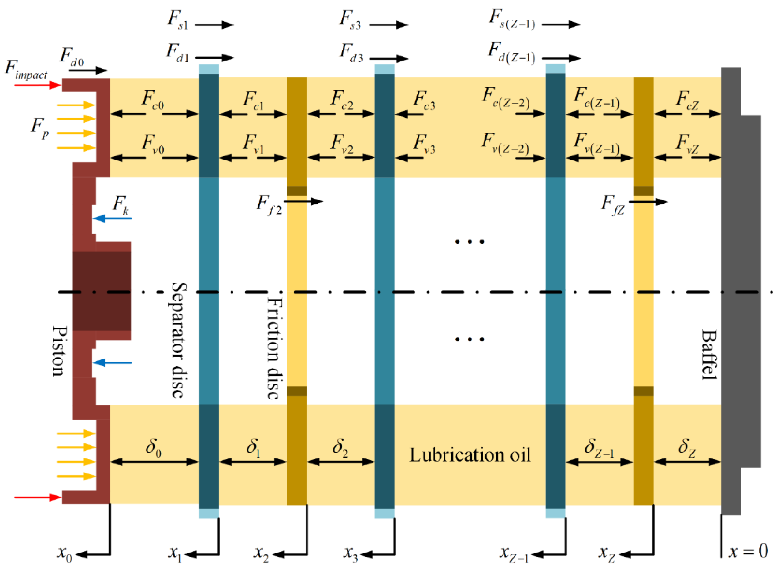
2.1. Axial Kinetic Model

During the disengaging process of a wet multi-disc clutch, the friction discs and separator discs together with the piston move axially, where the axial force analysis is illustrated in Figure 2.
Assuming that the number of friction pairs is Z, the friction components are successively numbered as 0, 1, 2, 3, …, Z − 1, and Z from the piston to the final friction disc. The force balance equation of each friction component can be expressed as:
{ F v 0 + F c 0 + F k F p F d 0 F i m p a c t = m 0 x ¨ 0 F v 1 + F c 1 F v 0 F c 0 F d 1 F s 1 = m 1 x ¨ 1 F v 2 + F c 2 F v 1 F c 1 F f 2 = m 2 x ¨ 2 F v ( Z 1 ) + F c ( Z 1 ) F v ( Z 2 ) F c ( Z 2 ) F d ( Z 1 ) F s ( Z 1 ) = m 1 x ¨ ( Z 1 ) F v Z + F c Z F v ( Z 1 ) F c ( Z 1 ) F f Z = m 2 x ¨ Z
where F k is the return spring force, F p is the hydraulic force, and F d 0 is the piston damping force; x ¨ is the acceleration of friction components; and m 0 , m 1 and m 2 are the weights of the piston, separator disc, and friction disc, respectively.
The gaps between adjacent friction components can be given as:
{ δ 0 = x 0 x 1 H s d δ 1 = x 1 x 2 H f d δ 2 = x 2 x 3 H s d δ Z 1 = x Z 1 x Z H f d δ Z = x Z
where x is the displacement of friction components; H s d and H f d are the thicknesses of the separator disc and friction disc, respectively.

2.2. Lubrication Model

It is assumed that the hydrodynamic pressure of the ATF film is axisymmetric and the boundary film pressure is equal to zero. Based on the uniform laminar flow assumption, considering the surface roughness effect and the permeability of friction material, the average oil film pressure is indicated as [4]:
p ¯ = B 4 A ( r 2 R o 2 ) + 3 η A h ¯ T t ( r 2 R o 2 ) + ln r R o ( B 4 A + 3 η A h ¯ T t ) R o 2 R i 2 ln R i ln R o
where r is the radius; R i and R o are the inner and outer radii of the friction pair, respectively; η is the dynamic viscosity of ATF; h ¯ T is the average oil film thickness. The coefficient A and B are noted as:
A = ϕ r h 3 + 12 Ψ d m
B = ϕ r ρ h 3 ( 3 ω f 1 2 + 4 ω f 1 ω f 2 + 3 ω f 2 2 ) / 5
where ϕ r is the pressure-flow factor [26], h is the nominal oil film thickness, and ρ is the density of ATF; Ψ and d m are the permeability and thickness of friction material, respectively; ω f 1 and ω f 2 are the angular velocities of the separator disc and friction disc, respectively.
With the Gaussian surface assumption [5], the change rate of average oil film thickness was deduced by Berger et al. [27]. By integrating the average oil film pressure in the ATF lubrication area A v , the hydrodynamic force of friction pairs can be deduced as:
F v = π { B 2 A + 3 η A d h d t [ 1 + erf ( h 2 σ ) ] } [ R i 4 R o 4 4 ( R o 2 R i 2 ) 2 4 ( ln R i ln R o ) ] ( 1 A red C )
where σ is the standard deviation of roughness, and A red is the non-groove area ratio.
The ATF film also exists between the piston and the first separator disc, contributing to the generation of a hydrodynamic force. As both the piston and the first separator disc are made of steel and rotate at the same speed, the hydrodynamic force between them can be expressed as follows by simplifying Equation (6).
F v = π { ρ ω f 1 2 + 3 η ϕ r h 3 d h d t [ 1 + erf ( h 2 σ ) ] } [ R i 4 R o 4 4 ( R o 2 R i 2 ) 2 4 ( ln R i ln R o ) ] ( 1 C )

2.3. Contact Model

The Cu-based friction material is mainly in the elastic–plastic contact status and the contact ratio of the real contact area A c , and the nominal contact area A n is defined as [5]:
C = A c A n = κ π 2 ( N β σ ) 2 [ 1 2 ( H 2 + 1 ) erfc ( H 2 ) H 2 π e H 2 2 ]
where κ is the plastic deformation coefficient; N and β are the density and radius of asperity, respectively; and H = h / σ is the film thickness ratio.
The asperity contact pressure is presented as [26]:
{ p c = K E 4.4086 × 10 5 ( 4 H ) 6.804 ,     H < 4 p c = 0 ,                                                                                                                       H 4
where K is the contact coefficient [5], and E is the effective Young’s modulus.
Thus, the contact force can be deduced as:
F c = π ( R o 2 R i 2 ) p c A red C

2.4. Sliding Model

For a wet clutch, the sum of the contact torque M c and the hydrodynamic torque M ν is the friction torque M f , which can be deduced as [5]:
M ν = π 2 ( 1 A red C ) η ( ϕ f + ϕ f s ) Δ ω h ( R o 4 R i 4 )
M c = 2 π 3 A red C μ p c ( R o 3 R i 3 )
where ϕ f and ϕ f s are the shear stress factors [26], and Δ ω is the angular speed difference. The coefficient of friction μ is obtained by the pin-on-disc experiments [28], which is presented as:
μ = 23 e { 2.6 V ( ln T 3.2 ) [ ( 28.3 P ) 0.4 0.87 ] 5.16 } + 0.08 ( e 0.005 T 1 ) ( e 0.2 V 1 ) + 0.01 ln ( 4 V + 1 ) e 0.005 T 0.005 ln ( 28.3 P ) + 0.035
where V is the linear velocity difference, T is the ATF temperature, and P is the applied pressure of a friction pair.
Finally, the torque balance equation of the clutch system is given as:
I f 1 d ω f 1 d t = i = 1 Z M f i M R
where I f 1 and M R are the inertia and resistance torque of the driven end, respectively.

2.5. Thermal Model

During the clutch disengaging process, the applied pressure is quickly removed and the friction heat generated is almost negligible. Thus, it is assumed that the ATF temperature keeps constant during the disengaging process. The dynamic viscosity of ATF is expressed as follows [29].
η = η 0 exp { ( ln η 0 + 9.67 ) [ ( 1 + 5.1 × 10 9 P ) s 1 × ( T 138 T 0 138 ) s 2 1 ] }
where s 1 and s 2 are the Roelands’ parameters.

2.6. Spline Resistance Model

A spline friction force will generate during the axial movement of discs [30,31]. For the friction discs, the spline friction force is deduced as:
F f = sign ( x ˙ ) μ spline M f R f cos α f
where x ˙ is the velocity of the friction components, and μ spline is the spline friction coefficient; and R f and α f are the pitch radius and pressure angle of the inner spline, respectively.
Similarly, the spline friction force of separator discs is deduced as:
F s = sign ( x ˙ ) μ spline M f R s cos α s
where R s and α s are the pitch radius and pressure angle of the outer spline, respectively.
Furthermore, the spline damping force of separator discs is demonstrated as:
F d = c s x ˙
where c s is the damping coefficient, which depends on the spline structural parameters.

2.7. Piston Impact Model

During the clutch disengaging process, the kinetic energy of the piston does not reduce to zero instantly when the piston reaches its limit position but is exhausted during the impact between the piston and clutch hub. However, the impact will affect the separation of friction pairs dramatically. To calculate the acceleration and velocity of the piston in the impact motion, the LN contact force model [32] is used to describe the impact force. Thus, the impact force of the piston is indicated as:
F i m p a c t = K 0 ξ n [ 1 + 3 ( 1 e 2 ) 4 ξ ˙ ξ ˙ ( ) ]
where K 0 is the stiffness of impact, n is the impact coefficient, e is the recovery coefficient, ξ is the local relative indentation, and ξ ˙ ( ) is the initial indentation velocity.

3. Numerical Simulation

The simulation flow chart is shown in Figure 3. Firstly, the forces are calculated using the initial status or the simulation results of the previous time step. Then, the accelerations, velocities, and displacements are obtained by solving the force balance equations. After that, the gaps and their change rates are calculated using the displacements and velocities, respectively. Finally, the calculation process above is repeated until the simulation termination time.
At the beginning of the simulation, the wet multi-disc clutch is in the disengagement status (D), then goes through the engaging process (A), the engagement status (B), and the disengaging process (C), and finally goes back to the disengagement status under the control of hydraulic oil. The variation of hydraulic pressure Papp is shown in Figure 4. From 0 s to 0.3 s, the hydraulic pressure increases linearly from 0 MPa to 0.36 MPa. From 0.3 s to 0.5 s, the hydraulic pressure continues to increase linearly from 0.36 MPa to 1.8 MPa and then keeps constant. The disengaging process starts when the hydraulic pressure starts to decline at 1.5 s. From 1.5 s to 1.6 s, the hydraulic pressure declines rapidly from 1.8 MPa to 0.05 MPa and then declines slowly to 0 MPa at 5 s.
When the ATF temperature is 80 °C, the variation of rotating speed of separator discs nf1 is shown in Figure 4, the initial and final values of which are 0 rpm. Moreover, the rotating speed of friction discs nf2 is simplified to keep constant at 1000 rpm. To show the change of the gap between the piston and the first separator disc, the initial value of which is set to 0.05 mm, and the initial gap of the first friction pair is set to 0.45 mm. The initial gap of other friction pairs is set to 0.5 mm, which is equal to the ideal uniform disengaging gap [18]. Other input parameters of the simulation are shown in Table 1. To study the influence of the ATF temperature on the disengaging dynamic characteristics, it is equally divided into five levels from 60 °C to 140 °C, and named from T1 to T5.

4. Results and Discussion

4.1. Disengaging Duration

The variation of gaps in the disengaging process with different ATF temperatures is shown in Figure 5a–e. It can be found that the friction pair gaps first increase slowly, then increase rapidly and finally stabilize after fluctuation during the disengaging process. In addition, the first friction pair gap δ1 fluctuates most dramatically and lasts the longest. Accordingly, the disengaging process is completed after the stabilization of the first friction pair gap. The disengaging moment t3 with different ATF temperatures is presented in Table 2.
As the ATF temperature increases from 60 °C to 140 °C, the disengaging moment is advanced from 1.745 s to 1.610 s, and the corresponding disengaging durations are 0.245 s, 0.174 s, 0.14 s, 0.121 s, and 0.11 s, respectively. Therefore, the increase of ATF temperature significantly shortens the disengaging duration (shortened by 55.1%), but its influence is getting weaker and weaker.

4.2. Disengaging Uniformity

The friction pair gaps after the disengaging process with different ATF temperatures are presented in Table 2. It can be found that the disengaged friction pair gaps decrease from the first friction pair to the sixth friction pair in sequence. However, it is not intuitionistic to directly evaluate the disengaging uniformity through the value of friction pair gaps for a wet multi-disc clutch. Therefore, the NUC is proposed to characterize the disengaging uniformity, which is expressed as:
NUC = 1 Z i = 1 Z 1 1 + δ i / δ *
where δ * is the ideal uniform disengaging gap. The NUC is inversely proportional to the value of friction pair gaps, the value range of which is 1 > NUC > 0.5. The smaller the NUC is, the more evenly distributed the disengaged friction pairs are.
The variation of the NUC in the disengaging process with different ATF temperatures is shown in Figure 5f. During the disengaging process, the NUC first decreases slowly then decreases rapidly and fluctuates with the fluctuation of friction pair gaps, finally stabilizing. With the decrease of the NUC, the discs separate more and more rapidly. The NUCs after the disengaging process with different ATF temperatures are presented in Table 2.
As the ATF temperature increases from 60 °C to 80 °C, the NUC decreases from 0.5825 to 0.5761. However, as the ATF temperature increases from 80 °C to 120 °C, the NUC sees a slight increase from 0.5761 to 0.5784. As the ATF temperature continues to increase, the NUC can hardly be changed. Therefore, with the increase of ATF temperature, the disengaging uniformity first increases, then decreases slightly, and the disengaged friction pair gaps at 80 °C distribute most uniformly.

4.3. Lubrication Status

During the disengaging process, the wet clutch goes through the boundary lubrication stage (C1), mixed lubrication stage (C2), and hydrodynamic lubrication stage (C3) in sequence (the division of T2 is marked in Figure 5f and Figure 6). The variations of the contact and hydrodynamic torque in the disengaging process with different ATF temperatures are shown in Figure 6. When the hydrodynamic torque starts to increase, the boundary lubrication stage finishes. When the contact torque reduces to zero (less than 10−6 N·m), the mixed lubrication stage finishes. The end moment of the boundary lubrication stage t1 and the end moment of the mixed lubrication stage t2 with different ATF temperatures are presented in Table 2.
As the ATF temperature increases from 60 °C to 140 °C, the end moment of the boundary lubrication stage brings forward from 1.575 s to 1.558 s, and the durations of the boundary lubrication stage are 0.075 s, 0.068 s, 0.063 s, 0.06 s, and 0.058 s, respectively. Similarly, the end moment of the mixed lubrication stage also brings forward from 1.674 s to 1.591 s, and the durations of the mixed lubrication stage are 0.099 s, 0.063 s, 0.047 s, 0.039 s, and 0.033 s, respectively; the durations of the hydrodynamic lubrication stage are 0.071 s, 0.043 s, 0.03 s, 0.022 s, and 0.019 s, respectively. Thus, the increase of ATF temperature accelerates the change of lubrication status between friction pairs during the disengaging process and shortens the duration of the hydrodynamic (shortened by 73.2%), mixed (shortened by 66.7%), and boundary (shortened by 22.7%) lubrication stages, respectively.

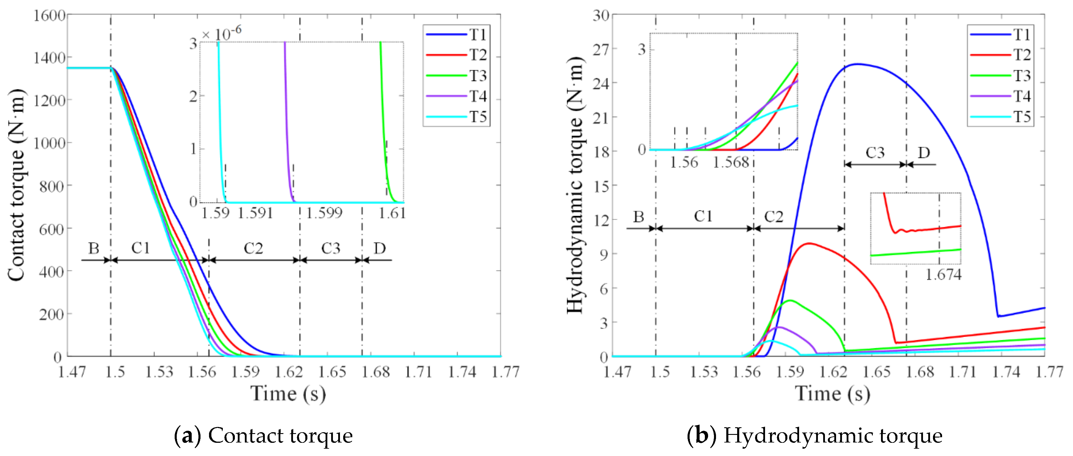
4.4. Friction Torque

As shown in Figure 6a, the contact torque first decreases rapidly, then decreases slowly in the boundary and mixed lubrication stages. As shown in Figure 6b, the hydrodynamic torque first increases dramatically, then decreases significantly, and fluctuates with the fluctuation of friction pair gaps, finally increasing slowly with the increase of speed difference in the mixed and hydrodynamic lubrication stages.
As the ATF temperature increases from 60 °C to 140 °C, the average decrease rate of contact torque increases sequentially during the boundary and mixed lubrication stages, which are 7753 N·m/s, 10298 N·m/s, 12264 N·m/s, 13626 N·m/s and 14824 N·m/s, respectively. Furthermore, the maximum value of hydrodynamic torque during the disengaging process decreases sequentially, which are 25.6 N·m, 9.89 N·m, 4.89 N·m, 2.54 N·m, and 1.35 N·m, respectively. Moreover, the hydrodynamic torque at the disengaging moment also decreases sequentially, which are 3.75 N·m, 1.24 N·m, 0.54 N·m, 0.26 N·m, and 0.14 N·m, respectively. Therefore, the increase of ATF temperature significantly enlarges the decrease rate of contact torque (enlarged by 91.2%) and dramatically decreases the hydrodynamic torque (decreased by 94.7%) during the disengaging process.

5. Conclusions

In this paper, a numerical simulation model was presented to study the disengaging process of a Cu-based wet multi-disc clutch, considering the hydrodynamic lubrication, the asperity contact, the heat transfer, the spline resistance, and the impact between the piston and clutch hub. The influence of ATF temperature on the disengaging dynamic characteristics of a six-friction-pair wet clutch was discussed. The conclusions were summarized as follows:
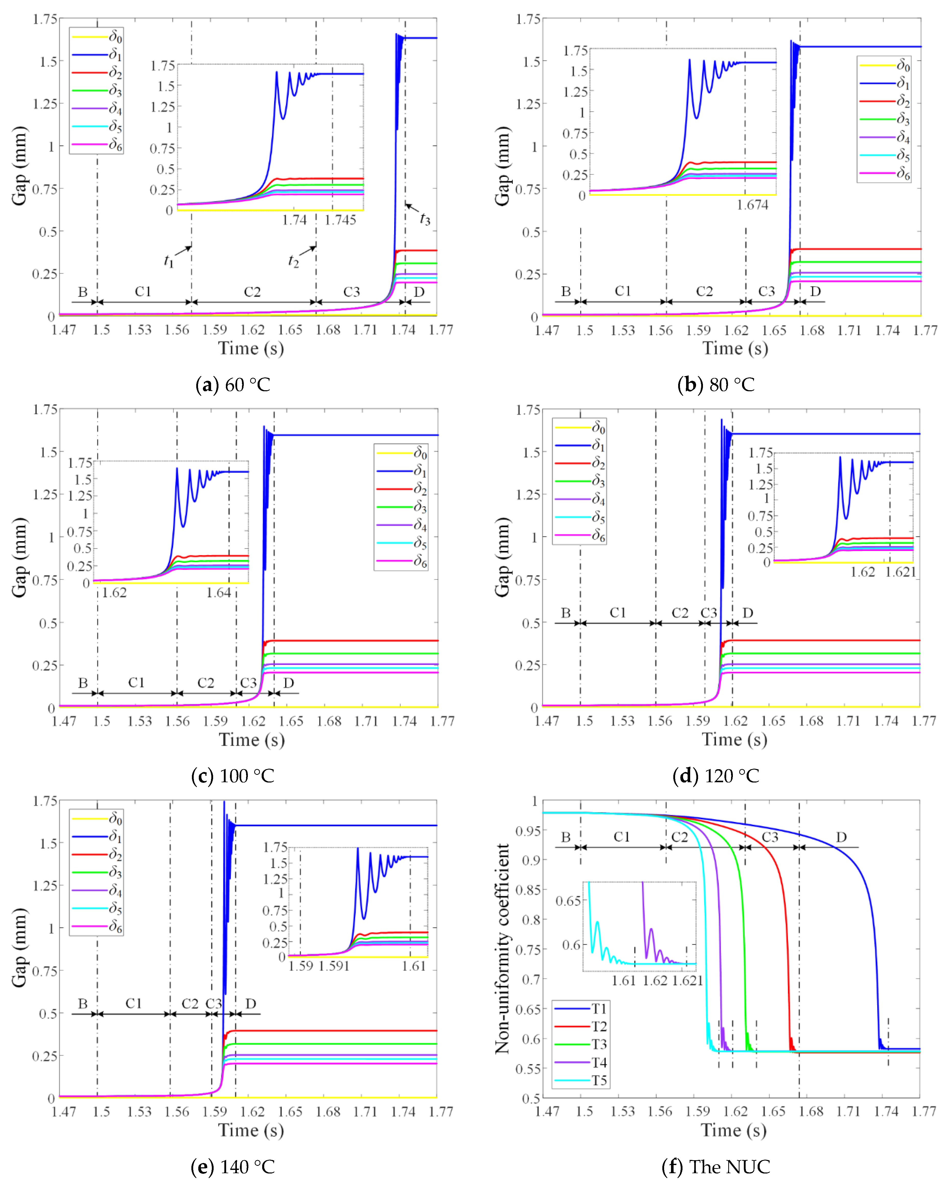
  • The friction pair gaps first increased slowly, then increased rapidly, finally stabilized after fluctuation during the disengaging process. When the first friction pair gap stabilized, the disengaging process was completed. The increase of ATF temperature (from 60 °C to 140 °C) significantly shortened the disengaging duration (shortened by 55.1% from 0.245 s to 0.11 s), but its influence became weaker and weaker.
  • The disengaged friction pair gaps decreased from the first friction pair to the sixth friction pair in sequence. With the increase of ATF temperature, the NUC first decreased then increased slightly, indicating that the disengaging uniformity first increased then decreased slightly. The disengaged friction pair gaps were distributed most uniformly when the ATF temperature was 80 °C.
  • The disengaging process of a wet multi-disc clutch included the boundary, mixed, and hydrodynamic lubrication stages in sequence. The increase of ATF temperature accelerated the change of lubrication status between friction pairs, shortened the duration of the boundary lubrication stage slightly, and lessened the duration of the mixed and hydrodynamic lubrication stages significantly in the disengaging process.
  • The contact torque decreased in the disengaging process, and the increase of ATF temperature significantly promoted its decrease (promoted by 91.2%). The hydrodynamic torque first increased sharply, then decreased significantly, and finally increased slowly after fluctuation during the disengaging process, and was dramatically reduced by the increase of ATF temperature (reduced by 94.7%).

Author Contributions

Conceptualization, B.M. and M.C.; Data curation, L.Z.; Formal analysis, B.M. and L.Y.; Funding acquisition, B.M. and M.C.; Investigation, L.Z.; Methodology, L.Z.; Project administration, M.C.; Software, L.Z.; Supervision, B.M.; Validation, L.Z.; Visualization, L.Z.; Writing—original draft, L.Z.; Writing—review & editing, L.Z., L.Y. and Q.W. All authors have read and agreed to the published version of the manuscript.

Funding

This research was funded by the National Natural Science Foundation of China (Grant No. 52175037, No. 51975047 and No. 51805289).

Institutional Review Board Statement

Not applicable.

Informed Consent Statement

Not applicable.

Data Availability Statement

Not applicable.

Conflicts of Interest

The authors declare no conflict of interest.

Nomenclature

ATFlubrication oil R i inner radius of friction pair (m)
CFDcomputational fluid dynamics R o outer radius of friction pair (m)
NUCnon-uniformity coefficient T temperature (°C)
A red non-groove area ratio V linear velocity difference (m/s)
c s damping coefficient (N·s/m) x displacement (m)
d m thickness of friction material (m) x ˙ velocity (m/s)
e recovery coefficient x ¨ acceleration (m/s2)
E Young’s modulus (Pa) Z number of friction pairs
h nominal oil film thickness (m) β asperity radius (m)
H film thickness ratio δ gap (m)
H f d thickness of friction disc (m) Δ ω angular speed difference (rad/s)
H s d thickness of separator disc (m) ξ local relative indentation (m)
I f 1 inertia of driven end (kg·m2) ξ ˙ ( ) initial indentation velocity (m/s)
K 0 stiffness of impact (N/m) η dynamic viscosity (Pa·s)
K contact coefficient μ coefficient of friction
m 0 weight of piston (kg) μ spline spline friction coefficient
m 1 weight of separator disc (kg) σ roughness (m)
m 2 weight of friction disc (kg) ϕ r pressure flow factor
M R resistance torque (N·m) ϕ f , ϕ f s shear stress factors
n impact coefficient Ψ permeability (m2)
N asperity density (/m2) κ plastic deformation coefficient
P applied pressure (Pa) ρ density (kg/m3)

References

  1. Li, M.; Khonsari, M.M.; McCarthy, D.M.C.; Lundin, J. Parametric analysis for a paper-based wet clutch with groove consideration. Tribol. Int. 2014, 80, 222–233. [Google Scholar] [CrossRef]
  2. Bao, H.; Huang, W.; Lu, F. Investigation of engagement characteristics of a multi-disc wet friction clutch. Tribol. Int. 2021, 159, 106940. [Google Scholar] [CrossRef]
  3. Leister, R.; Najafi, A.F.; Gatti, D.; Kriegseis, J.; Frohnapfel, B. Non-dimensional characteristics of open wet clutches for advanced drag torque and aeration predictions. Tribol. Int. 2020, 152, 106442. [Google Scholar] [CrossRef]
  4. Yu, L.; Ma, B.; Chen, M.; Li, H.; Liu, J.; Zheng, L. Numerical and experimental studies on the characteristics of friction torque based on wet paper-based clutches. Tribol. Int. 2019, 131, 541–553. [Google Scholar] [CrossRef]
  5. Yu, L.; Ma, B.; Chen, M.; Xue, J.; Zhao, P. Variation mechanism of the friction torque in a Cu-based wet clutch affected by operating parameters. Tribol. Int. 2020, 147, 106169. [Google Scholar] [CrossRef]
  6. Wu, B.; Qin, D.; Hu, J.; Wang, X.; Wang, Y.; Lv, H. Analysis of influencing factors and changing laws on friction behavior of wet clutch. Tribol. Int. 2021, 162, 107125. [Google Scholar] [CrossRef]
  7. Wu, B.; Qin, D.; Hu, J.; Liu, Y. Experimental data mining research on factors influencing friction coefficient of wet clutch. J. Tribol. 2021, 143, 121802. [Google Scholar] [CrossRef]
  8. Wang, Y.; Li, Y.; Liu, Y.; Zhang, W. Modeling and experimental research on engaging characteristics of wet clutch. Ind. Lubr. Tribol. 2019, 71, 94–101. [Google Scholar] [CrossRef]
  9. Wang, Y.; Yang, K.; Wu, X. Structural design and friction performance test of a new conical groove friction disks in wet clutch. Appl. Sci. 2021, 11, 7231. [Google Scholar] [CrossRef]
  10. Yu, L.; Ma, B.; Chen, M.; Li, H.Y.; Liu, J. Experimental study on the friction stability of paper-based clutches concerning groove patterns. Ind. Lubr. Tribol. 2020, 72, 541–548. [Google Scholar] [CrossRef]
  11. Bao, H.; Zhang, C.; Hou, X.; Lu, F. Wear characteristics of different groove-shaped friction pairs of a friction clutch. Appl. Sci. 2021, 11, 284. [Google Scholar] [CrossRef]
  12. Marklund, P.; Mäki, R.; Larsson, R.; Höglund, E.; Khonsari, M.M.; Jang, J. Thermal influence on torque transfer of wet clutches in limited slip differential applications. Tribol. Int. 2007, 40, 876–884. [Google Scholar] [CrossRef]
  13. Meng, Q.; Tian, Z.; Zhao, C. Non-uniform contact characteristics of the friction disc during the initial period of a braking process. J. Mech. Sci. Technol. 2018, 32, 1261–1268. [Google Scholar] [CrossRef]
  14. Bao, H.; Kong, W.; Hou, X.; Zhu, R. Analysis on temperature field of friction pair of aviation friction clutch based on different groove shapes of friction disk. J. Mech. Sci. Technol. 2021, 35, 3735–3742. [Google Scholar] [CrossRef]
  15. Zhao, E.H.; Ma, B.; Li, H.Y. Wear and lubrication behaviors of Cu-based friction pairs with asperity contacts: Numerical and experimental studies. Tribol. Lett. 2017, 65, 69. [Google Scholar] [CrossRef]
  16. Ma, B.; Yu, L.; Chen, M.; Li, H.Y.; Zheng, L.J. Numerical and experimental studies on the thermal characteristics of the clutch hydraulic system with provision for oil flow. Ind. Lubr. Tribol. 2019, 71, 733–740. [Google Scholar] [CrossRef]
  17. Wu, P.; Zhou, X.; Yang, C.; Lv, H.; Lin, T.; Wu, X. Parametric analysis of the drag torque model of wet multi-plate friction clutch with groove consideration. Ind. Lubr. Tribol. 2018, 70, 1268–1281. [Google Scholar] [CrossRef]
  18. Iqbal, S.; Al-Bender, F.; Pluymers, B.; Desmet, W. Model for predicting drag torque in open multi-disks wet clutches. ASME J. Fluid Eng. 2014, 136, 021103. [Google Scholar] [CrossRef]
  19. Hu, J.; Hou, S.; Wei, C. Drag torque modeling at high circumferential speed in open wet clutches considering plate wobble and mechanical contact. Tribol. Int. 2018, 124, 102–116. [Google Scholar] [CrossRef]
  20. Neupert, T.; Bartel, D. High-resolution 3D CFD multiphase simulation of the flow and the drag torque of wet clutch discs considering free surfaces. Tribol. Int. 2019, 129, 283–296. [Google Scholar] [CrossRef]
  21. Neupert, T.; Bartel, D. Measurement of pressure distribution and hydrodynamic axial forces of wet clutch discs. Tribol. Int. 2021, 163, 107172. [Google Scholar] [CrossRef]
  22. Cui, J.; Hou, P.; Zhang, B.; Zhao, X. Investigation of flow between deformed disks in hydro-viscous drive. Tribol. Int. 2018, 121, 287–301. [Google Scholar] [CrossRef]
  23. Cui, J.; Xie, F.; Li, H.; Zhao, X. Influences of deformed film gaps on dynamic torque behavior of hydroviscous drive. Tribol. Trans. 2021, 64, 477–500. [Google Scholar] [CrossRef]
  24. Wang, P.; Katopodes, N.; Fujii, Y. Statistical modeling of plate clearance distribution for wet clutch drag analysis. SAE Int. J. Passeng. Cars-Mech. Syst. 2018, 11, 76–88. [Google Scholar] [CrossRef]
  25. Fu, Y.; Liu, Y.; Cui, L.; Xu, X. Dynamic analysis and control strategy of wet clutches during torque phase of gear shift. J. Mech. Sci. Technol. 2016, 30, 1479–1496. [Google Scholar] [CrossRef]
  26. Patir, N.; Cheng, H.S. Application of average flow model lubrication between rough sliding surfaces. J. Lubr. Technol. 1979, 101, 220–229. [Google Scholar] [CrossRef]
  27. Berger, E.J.; Sadeghi, F.; Krousgrill, C.M. Analytical and numerical modeling of engagement of rough, permeable, grooved wet clutches. J. Tribol. 1997, 119, 143–148. [Google Scholar] [CrossRef]
  28. Zhao, E.H.; Ma, B.; Li, H.Y. Numerical and experimental studies on tribological behaviors of Cu-based friction pairs from hydrodynamic to boundary lubrication. Tribol. Trans. 2018, 61, 347–356. [Google Scholar] [CrossRef]
  29. Houpert, L. New results of traction force calculations in elastohydrodynamic contacts. J. Tribol. 1985, 107, 241–245. [Google Scholar] [CrossRef]
  30. Yu, L.; Ma, B.; Chen, M.; Li, H.; Zhang, H.; Liu, J. Thermodynamic differences of different friction pairs in a multidisc clutch caused by spline friction: Numerical simulation and experimental verification. Tribol. Trans. 2019, 62, 724–736. [Google Scholar] [CrossRef]
  31. Chen, M.; Zhang, B.; Feng, Y.; Wang, L.; Wang, H. Numerical and experimental studies of the attenuation characteristics of friction torque in a wet multidisc clutch. Appl. Sci. 2021, 11, 814. [Google Scholar] [CrossRef]
  32. Lankarani, H.M.; Nikravesh, P.E. A contact force model with hysteresis damping for impact analysis of multibody systems. J. Mech. Des. 1990, 112, 369–376. [Google Scholar] [CrossRef]
Figure 1. Structure of the wet multi-disc clutch.
Applsci 11 11299 g001
Figure 2. Force analysis of the wet multi-disc clutch.
Applsci 11 11299 g002
Figure 3. Flow chart of the simulation.
Applsci 11 11299 g003
Figure 4. Variations of the hydraulic pressure and rotating speeds.
Applsci 11 11299 g004
Figure 5. Variations of gaps and the NUC in the disengaging process with different ATF temperatures.
Applsci 11 11299 g005
Figure 6. Variations of torques in the disengaging process with different ATF temperatures.
Applsci 11 11299 g006
Table 1. Input data of the simulation.
ParameterValueParameterValueParameterValue
A red 0.68 m 0 /(kg)3 β /(m)8 × 10−4
c s /(N·s/m)0.0714 m 1 /(kg)0.45 μ spline 0.1
d m /(m)6 × 10−4 m 2 /(kg)0.6 σ /(m)8.4 × 10−6
E /(Pa)4.84 × 109 M R /(N·m)240 Ψ /(m2)2 × 10−12
H f d /(m)2 × 10−3 N /(m−2)7 × 107 κ 1.2332
H s d /(m)3.2 × 10−3 R i /(m)0.086 ρ /(kg/m3)875
I f 1 /(kg·m2)2 R o /(m)0.124
Table 2. Simulation results with different ATF temperatures.
NumberT1T2T3T4T5
T/(°C)6080100120140
δ1/(mm)1.63301.58221.59501.60341.6006
δ2/(mm)0.38520.39620.39260.39260.3956
δ3/(mm)0.30940.32000.31730.31620.3179
δ4/(mm)0.24670.25720.25480.25270.2526
δ5/(mm)0.22370.23380.23210.22980.2293
δ6/(mm)0.19680.20690.20570.20350.2025
NUC0.58250.57610.57740.57840.5782
t1/(s)1.5751.5681.5631.5601.558
t2/(s)1.6741.6311.6101.5991.591
t3/(s)1.7451.6741.6401.6211.610
Publisher’s Note: MDPI stays neutral with regard to jurisdictional claims in published maps and institutional affiliations.

