Article

An Analytical Model for Almost Conformal Spherical Contact Problems: Application to Total Hip Arthroplasty with UHMWPE Liner

Department of System Dynamics and Friction Physics, Technische Universität Berlin, Sekr. C8-4, Straße des 17. Juni 135, 10623 Berlin, Germany
*
Author to whom correspondence should be addressed.
Appl. Sci. 2021, 11(23), 11170; https://doi.org/10.3390/app112311170
Submission received: 20 October 2021 / Revised: 22 November 2021 / Accepted: 23 November 2021 / Published: 25 November 2021
(This article belongs to the Section Mechanical Engineering)

Abstract

:
Due to its high relevance for designing ball joints in mechanical engineering and (artificial) hip joints in biomechanics, the almost conformal elastic contact between a sphere and a spherical cup represents an important contact problem of current research. As no closed-form analytical solution to the problem has been found to date, full computational methods such as the finite element method are needed for analysis. However, they often require incredibly long, unacceptable calculation times, making parameter studies hardly practicable. For this reason, approximate analytical and semi-analytical models are applied, capable of predicting quantities of interest with sufficient accuracy. In the present work, a very simple model based on a radially directed Winkler foundation is presented, which provides (approximate) closed-form analytical solutions for both the pressure distribution and the dependencies between macroscopic contact quantities such as normal force and indentation depth. To ensure an optimal mapping of a specific contact problem, only the foundation modulus must be defined in a suitable way. As an example, the proposed model has been successfully adapted to adequately simulate the frictionless normal contact for hard-on-soft hip implants. For this purpose, the foundation modulus was approximated with the aid of a finite element analysis instead of adopting it from already well-established models, as the latter produce clearly erroneous results for large liner thicknesses and large Poisson’s ratios. By a comparison with extensive parameter studies of finite element simulations, it is demonstrated that the proposed model provides acceptable results for all commonly used hard-on-soft hip implants. On this basis, the influence of geometrical changes of the femoral head and the acetabular cup on the maximum pressure as well as the half-contact angle is discussed, and consequences on the wear behavior are deduced.

1. Introduction

Tribology is no longer just a field of research in mechanical engineering, it has entered almost all fields of sciences, including biology and medicine. Tribological problems from the latter areas are assigned to biotribology. It deals, for example, with human joint prosthesis, dental implants, bio-inspired adhesives, or friction-based surface haptics technologies [1,2,3,4]. Due to the multiscale roughness and a multitude of additional effects such as lubrication, adhesion or wear, such problems, if possible at all, can only be solved by full computational methods. However, they often require incredibly long, unacceptable calculation times, making parameter studies hardly practicable. For this reason, approximate analytical or semi-analytical models are still in use, which not only contribute to the qualitative understanding of contact problems but can also predict quantities of interest with sufficient accuracy [5]. One of the highest simplifications of contact problems is provided by models based on Winkler’s foundation. In a few cases, their application as approximate models has long been accepted, e.g., in railway track dynamics, as a model for ballast and subgrade, or biomechanics for mapping thin cartilage layers. Surprisingly, however, Winkler foundation models have experienced a kind of renaissance in the last decade. This is mainly due to the new recognition that from a mathematical point of view, any non-conformal contact problem with a circular contact area has an extremely simple one-dimensional equivalent in the Abel-transformed space. The latter consists of a one-dimensional Winkler foundation, which is subjected to stress by a rigid plane profile. Despite its simplicity, the one-dimensional model exactly reproduces the relationships between macroscopic quantities such as normal force, indentation depth and contact radius of the original axisymmetric contact problem [6]. This applies not only to normal contacts, but also to tangential contacts in a state of full stick, partial slip, or gross sliding and includes viscoelastic as well as elastic layered materials [7,8]. Due to the enormous reduction in degrees of freedom and the associated savings in computation time when calculating contact forces, the method is particularly well suited for mapping contact interfaces within simulations of macrodynamic systems. In addition, it can be applied for advanced tribological investigations such as wear calculations or the onset of plastic deformation, as both the stresses within the contact area as well as inside the body can be recovered from the one-dimensional model [9,10].
However, unfortunately, for the almost conformal contact problem of a sphere indenting a spherical cavity or socket with slightly larger radius of curvature, the method is not applicable. This very important problem, relevant for the design of spherical joints in engineering and (artificial) hip joints in biomechanics, requires alternative solution procedures. Although a closed form analytic solution for the analog two-dimensional problem of a pin in a conforming hole in an infinite plate has been known for almost 50 years [11], the conformal contact problem of a sphere indenting a spherical cavity has not been solved in a closed analytic way until today. An approximate numerical solution was given by Goodman and Keer [12]. Their results showed a considerably larger contact stiffness compared to that of the Hertzian theory. Further models that provide an approximate solution to the problem have emerged mainly from the field of biomechanics. This is not surprising, as intensive research is still being conducted in the field of hip arthroplasty with the aim of extending the lifespan of artificial hip joints, which is mainly limited by wear mechanisms, and improving their functionality [13]. More than 1 million artificial hip joints are implanted worldwide each year. At the same time, the age of patients who decide to undergo such a surgical intervention is decreasing more and more [14]. From contact mechanics point of view, the hip joint implant can be considered by a ball-in-socket model, where the head and the cup have approximately but not exactly the same radius of curvature, so that a small radial clearance remains (almost conformal contact). Jin [15] applied the usual procedure for non-conformal contacts and approximates the ball-in-socket model by an equivalent ball-on-plane model, which is solved numerically using the fundamental solution for the indentation into a linear elastic bonded layer. However, while the contact radius is insensitive to the mapping procedure, significant differences in the maximum pressure arises compared to FE calculations. The most frequently adopted model for a hard-on-soft implant such as a metal head on (metal backed) plastic was developed by Bartel et al. [16]. It is based on the solution of the elastic spherical vessel under uniform (internal and external) pressure, which implies that the tangential displacements present in the plastic layer are neglected. Several important findings emerged from the work of Bartel et al., e.g., bonding of the plastic layer on the metal avoids higher tensile stresses at the edge of the contact zone or the minimum thickness of the plastic layer (liner) should not be less than 4 mm. One problem of the model is that it does not provide a closed-form analytical solution for the force as a function of indentation depth; instead, a numerical solution is required. In addition, it is not applicable to liner materials with a Poisson’s ratio close to 0.5 (incompressible materials). Imado et al. [17] have demonstrated that already at a Poisson’s ratio of 0.46 the results from Bartel’s model clearly deviate from FE results. Thus, they introduced a correction factor, which is a linear function of the ratio of inner to outer radius of the cup, and was obtained by fitting on the maximum contact pressure of corresponding FE simulations. As the correction factor is always smaller than 0.883, it is concluded that the model of Bartel et al. considerably overestimates the stiffness. Jin et al. [18] performed a parametric analysis of the contact stress in ultra-high molecular weight polyethylene (UHMWPE) acetabular cups by means of a simplified model which uses the constrained column concept in radial direction (radial acting Winkler foundation) with stiffness taken from the model of Bartel et al. They studied the effects of layer thickness, radial clearance, radii of femoral head and cup, as well as contact area on maximum pressure. However, they also noted that values obtained from FEM were 10 to 20% higher than predicted by the simplified model. It is also common to adopt the original constrained column model that is often used to map contacts with thin cartilage layers attached to bones. In this model, the thin (plane) compressible elastic layer bonded to a rigid substrate acts similar to a linear Winkler foundation and its stiffness is specified by the modulus of constrained uniaxial compression [19,20,21,22,23]. However, the application of this bonded-layer-model generally requires certain assumptions to be satisfied. The Poisson’s ratio should not exceed 0.45 as the stiffness becomes unbounded in the limit of an incompressible material. Furthermore, the layer thickness must be much smaller than the linear dimensions of the contact area [18,24]. The latter condition is fulfilled for some but by no means all common geometric pairings of femoral head and acetabular cup in total hip arthroplasty.
In the present work, an approximate model for the almost conformal elastic contact between a sphere and a spherical cup is proposed, which leads to simple closed-form analytical solutions. As an application example, the frictionless normal contact of artificial hip joints is considered. It is demonstrated that the new model is able to predict the local and global contact mechanical quantities with great accuracy for all commonly used hard-on-soft hip implants. In Section 2, the kinematic and dynamic fundamentals of the model are explained and analytical equations for the normal force as a function of the indentation depth and the half-contact angle, respectively, are derived. Section 3 first deals with a special approach to optimize the foundation modulus and thus the stiffness of the model. Subsequently, the results of FE analyses are used to highlight further advantages of the new model over already well-established ones. At the end, parameter studies are performed by means of the new model and the corresponding results are rigorously discussed.

2. Methods

It is well-known that Hertzian theory can also be applied to contacts between elastic bodies whose surfaces are differently curved, one convex and the other concave. Such geometrical relations are present in a contact between a sphere and a spherical socket. If we denote the radii of curvature of the sphere and socket by R 1 and R 2 , the young’s moduli by E 1 and E 2 , and the Poisson’s ratios by ν 1 and ν 2 , Hertzian theory gives the following solution:
F N = 4 3 E * a 3 R * ,
δ = a 2 R * ,
where F N is the applied normal force, a the contact radius and δ the penetration/indentation depth. E * and R * are defined by
1 E * = 1 ν 1 2 E 1 + 1 ν 2 2 E 2 and R * = R 1 R 2 R 2 R 1 = R 1 R 2 Δ R .
However, this solution is only valid if the contact is non-conformal (incomplete). Among other things, this means that the contact radius must be much smaller than both the radii of curvature of the two surfaces, as well as the dimensions of each body. If the clearance Δ R between the sphere and the spherical socket is very small, the size of the contact area increases rapidly when a normal force is applied and can quickly reach the dimensions of the bodies themselves. In this case, an almost conformal contact is present for which the application of the half-space approximation is no longer valid. An indication that the solution according to Equation (1) does not hold for the limiting case R 1 R 2 is immediately obvious, as in this case R * approaches infinity, i.e., the transmission of a finite force would require an infinitely large contact radius. As mentioned above, there is not yet a closed-form analytical solution to this problem.
In the following, we present an approximate model, which provides quite simple closed-form analytical solutions. It consists of a rigid sphere indenting a radially directed Winkler foundation, illustrated in Figure 1 on the left, while its kinematics is shown on the right.
Straightforward application of the cosine theorem leads to the kinematic relation
R 1 2 = ( Δ R + δ ) 2 + ( R 2 + u r ( φ ) ) 2 2 ( Δ R + δ ) ( R 2 + u r ( φ ) ) cos φ ,
where u r ( φ ) denotes the radial displacement of the foundation at angle φ . The quadratic equation in R 2 + u r ( φ ) can be solved in an elementary way, yielding the radial displacement as a function of the angle:
u r ( φ ) = ( Δ R + δ ) ( cos φ + ( R 1 Δ R + δ ) 2 sin 2 φ ) R 2 .
Equation (5) was first given by Bartel et al. [16] to represent the kinematics of metal-on-plastic hip implants and has been adopted in other works as well (e.g., [23]). As an almost-conformal contact is assumed, allowing for the constraint R i Δ R (with i = 1 , 2 ), and small displacements and thus a small indentation depth R i δ are assumed, sin 2 φ under the root can be neglected with respect to the first term. In this way, a very simple, yet sufficiently accurate relationship is obtained for the almost conformal contact
u r ( φ ) = δ cos φ Δ R ( 1 cos φ ) .
At the edge of the contact, the radial displacement must be zero, i.e.,
u r ( ε ) = ! 0 ,
where ε denotes the half-contact angle. From this condition, the half-contact angle can be related to the indentation depth
cos ε = Δ R Δ R + δ .
The contact is considered as frictionless, so that no tangential stresses occur in the spherical contact area. The spring stresses of the Winkler foundation sketched on the left in Figure 1 are proportional to the spring displacements in the radial direction
p r ( φ ) = K u r ( φ ) ,
where K represents the foundation modulus. Note, that it is also called “subgrade reaction modulus” and has the unit of measure N/m3. It represents the elastic modulus of the foundation divided by the thickness of the foundation. The incremental contact force d F C in vertical direction produced by the pressure acting on an annular ring element of the spherical surface corresponding to an angle φ reads
d F C = p r ( φ ) cos φ d A an with d A an = 2 π R 2 sin φ R 2 d φ .
The whole contact force and thus the normal force result from the sum of the contributions of all loaded annular elements
F N = 2 π R 2 2 0 ε p r ( φ ) cos φ sin φ d φ .
After substituting Equation (9) into Equation (11) and taking Equation (6) into account, the integration yields
F N = 2 π R 2 2 K [ 1 3 ( Δ R + δ ) ( 1 cos 3 ε ) 1 2 Δ R sin 2 ε ] .
Thus, the normal force as a function of the half-contact angle is determined. Equation (8) can then be used to substitute the half-contact angle, which results in the normal force as a function of the indentation depth
F N = 1 3 π R 2 2 K [ 2 δ Δ R + Δ R ( Δ R Δ R + δ ) 2 ] .
Equations (8) and (12) provide an extremely simple closed-form analytical approximate solution for the almost conformal contact between a sphere and a spherical cup. Hence, the relationships between the macroscopic quantities normal force, indentation depth, and half-contact angle are completely defined. Moreover, the pressure distribution is given in a simple way via Equation (9) by taking Equation (6) into account. The proposed model can be applied to approximate the almost conformal contact of ball joints in mechanical engineering as well as ball-and-socket joints in biomechanics, e.g., (artificial) hip and shoulder joints.
One comparably simple model that also provides closed-form analytical solutions was developed by Liu et al. [25]. Unfortunately, without any physical explanation, they mapped the contact within a spherical joint with clearance onto an equivalent contact of a rigid cone and a plane Winkler foundation whose thickness is given by the radius of the original spherical cavity. They have even presumed a priori that the contact stress distribution in vertical direction along the profile of the rigid cone is ellipsoidal, as given by Hertzian theory. After fitting the maximum pressure by an introduced parameter, the force as a function of indentation depth obtained with their model agrees well with the results of an FE simulation, especially for small clearances. However, although they investigate the influence of the radial clearance, they do not vary the thickness of the spherical shell. In addition, it is explicitly stated that identical linear elastic materials are assumed.
In the following, the proposed model will be adapted to adequately simulate the frictionless normal contact for commonly used hard-on-soft hip implants. For this purpose, the foundation modulus must be determined.

3. Application to Total Hip Arthroplasty with UHMWPE Liner

As an application example, we consider the contact in total hip arthroplasty (THA) with a stiff steel head and a soft plastic liner in the acetabular cup. As the clearance between head and inner cup radius is very small, the contact can be described as almost conformal. Typically, the liner sits inside a metallic acetabular shell that is fixated to the hip bones. Thus, the maximum outer cup radius is limited by individual anatomy. Table 1 summarizes the available head radii and liner thicknesses as well as the commonly used radial clearances and outer cup radii.
The traditionally used plastic material for the plastic liner is ultra-high molecular weight polyethylene (UHMWPE). Recently, radiation cross-linking of UHMWPE has been used to increase the wear resistance. Even though the radiation changes all mechanical properties slightly, the elastic modulus is measured in the range 0.5–1 GPa for both conventional and cross-linked UHMWPE [13,28]. For the Poisson’s ratio, values of 0.4–0.46 are commonly assumed [13,29]. The material properties used for the application example are shown in Table 2.
A convenient way to configure the new model for mapping the normal contact in total hip arthroplasty is to adopt the foundation modulus from already established models. One possibility would be to take the foundation modulus from the famous model of Bartel et al. [16], which reads
K B = 2 ( 1 2 ν ) + ( 1 + ν ) κ 3 ( 1 + ν ) ( 1 2 ν ) ( 1 κ 3 ) E R 2 with κ : = R 2 R 2 + L .
In contrast to the original model of Bartel et al., which must be evaluated numerically, very simple closed-form analytical solutions are obtained. In the range of small radial clearances (almost conformal contact), both models give almost the same results. However, it is well-known that the stiffness of the model of Bartel et al. originates from the elastic spherical vessel under uniform (internal and external) pressure and thus is somewhat larger than that of the liner. Noticeable deviations occur, especially for larger Poisson’s ratios [17,18,30]. This is already evident from Equation (14), as for incompressible material, ν 1 / 2 , the foundation modulus becomes unbounded. The same holds for the foundation modulus of the constrained column model, which in the following is also called bonded-layer-model. It is defined by
K BL = ( 1 ν ) ( 1 + ν ) ( 1 2 ν ) E L .
and originates from the indentation into a very thin plane compressible layer bonded to a rigid substrate. In addition to the constraint ν < 0.45 , it is assumed that the linear dimensions of the contact area are much larger than the layer thickness to justify neglecting in-plane deformations and to ensure constrained uniaxial compression [24]. The model is widely applied to map the indentation into thin cartilage layers [19,20,21,22]. However, its application to ball-in-socket contact is questionable, at least for larger liner thicknesses that reach the order of linear dimensions of the contact area.
For the above reasons, we avoid adopting the foundation modulus from other models here. To determine the foundation modulus (stiffness of the foundation per unit area) and to validate the predictions of the new model, an axisymmetric finite element analysis was conducted with the software Abaqus FEA. For all considered geometries, the generated mesh consisted of four-noded axisymmetric quadrilateral elements with a minimum element size of 0.05 mm at the contacting interfaces. In case of a 12 mm head with an 8 mm liner, this resulted in approximately 27,000 elements for the head and 40,000 elements for the liner. Using approximately twice as many elements yielded an increase of less than 1% in normal force, contact angle and maximum contact pressure. The loading was applied by prescribing a displacement to the cross section of the lower hemisphere of the head. It is assumed that the plastic liner is bonded to a much stiffer metal backing. Thus, the displacements at the outside of the liner were fixed [18,23]. In agreement with the low coefficient of friction measured in the lubricated contact in THA ( μ 0.06   [13]), the contact was assumed to be frictionless.

3.1. Determination of the Foundation Modulus

From Equations (6) and (9), it is immediately obvious that in the proposed model, the maximum pressure p 0 and the maximum displacement (indentation depth) δ , are located at φ = 0 ° and directly proportional to each other. The foundation modulus represents the proportionality factor
K = p 0 δ .
For further evaluations, the dimensionless foundation modulus defined by
K ˜ = R 2 E K = R 2 p 0 E δ .
is introduced, where R 2 is the inner cup radius and E is the elastic modulus of the UHMWPE liner. In order to derive a universal expression for the foundation modulus that yields acceptable results for all common geometries, the maximum contact pressures p 0 of the FEM solution are considered at a given indentation depth δ . Owing to the large difference in elastic moduli (see Table 2), it is assumed that only the liner is deformed.
Figure 2 shows the dimensionless foundation stiffness per unit area as predicted by FEM for different Poisson’s ratios plotted against normal force F N , radial clearance Δ R , and ratio of inner cup radius to foundation thickness R 2 / L . As shown in the left plot, the assumption of a constant foundation stiffness is only appropriate for normal forces larger than 1000 N. Slight deviations occur only for ν = 0.45 , which consequently become noticeable in the later results as well. During gait, up to 3000 N are commonly reached [27] such that the most important loading range can be covered by the spring model. To consider the effect of clearance and cup geometry, the foundation modulus in the range of 1000–3000 N was averaged and presented in the other plots. For different clearances in the range of interest (see Table 1), it is shown that the foundation modulus can be assumed to be approximately constant. Specifying parameters for the foundation modulus are the Poisson’s ratio of the liner and the ratio of inner cup radius to liner thickness. For high Poisson’s ratios, the increasing incompressibility yields larger foundation stiffnesses in very confined situations, i.e., very small clearances or small liner thicknesses.
In order to find a universal expression of the foundation modulus in the discussed ranges, a polynomial fit of the FEM results in terms of cup geometry was obtained for each considered Poisson’s ratio:
K ˜ = C 1 ( ν ) + C 2 ( ν ) R 2 L + C 3 ( ν ) ( R 2 L ) 2 ,
where the constants C i ( ν ) are listed in Table 3. In Figure 2, the fit is plotted in dotted lines. The derived stiffness function is in very good agreement with the FEM results for all Poisson’s ratios.

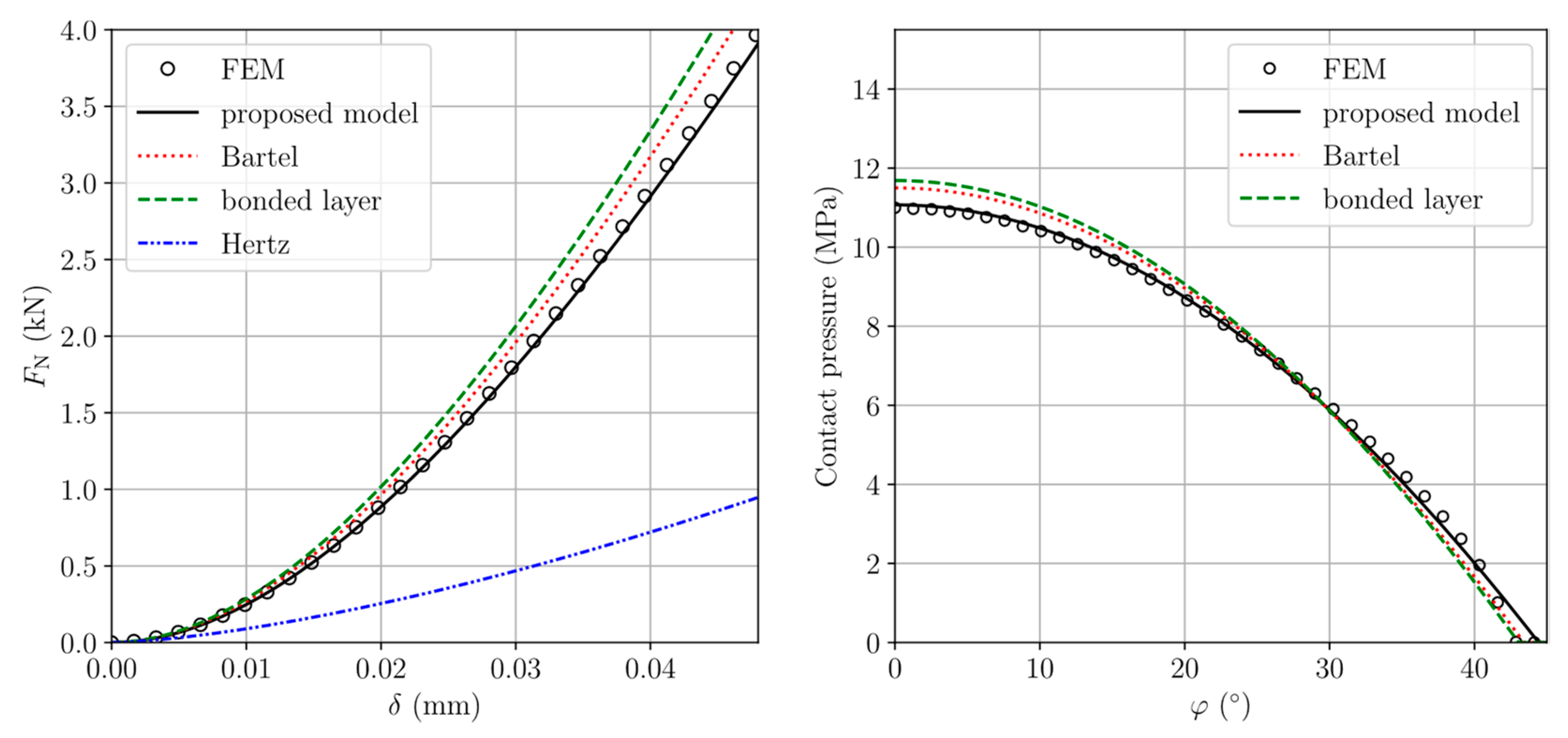
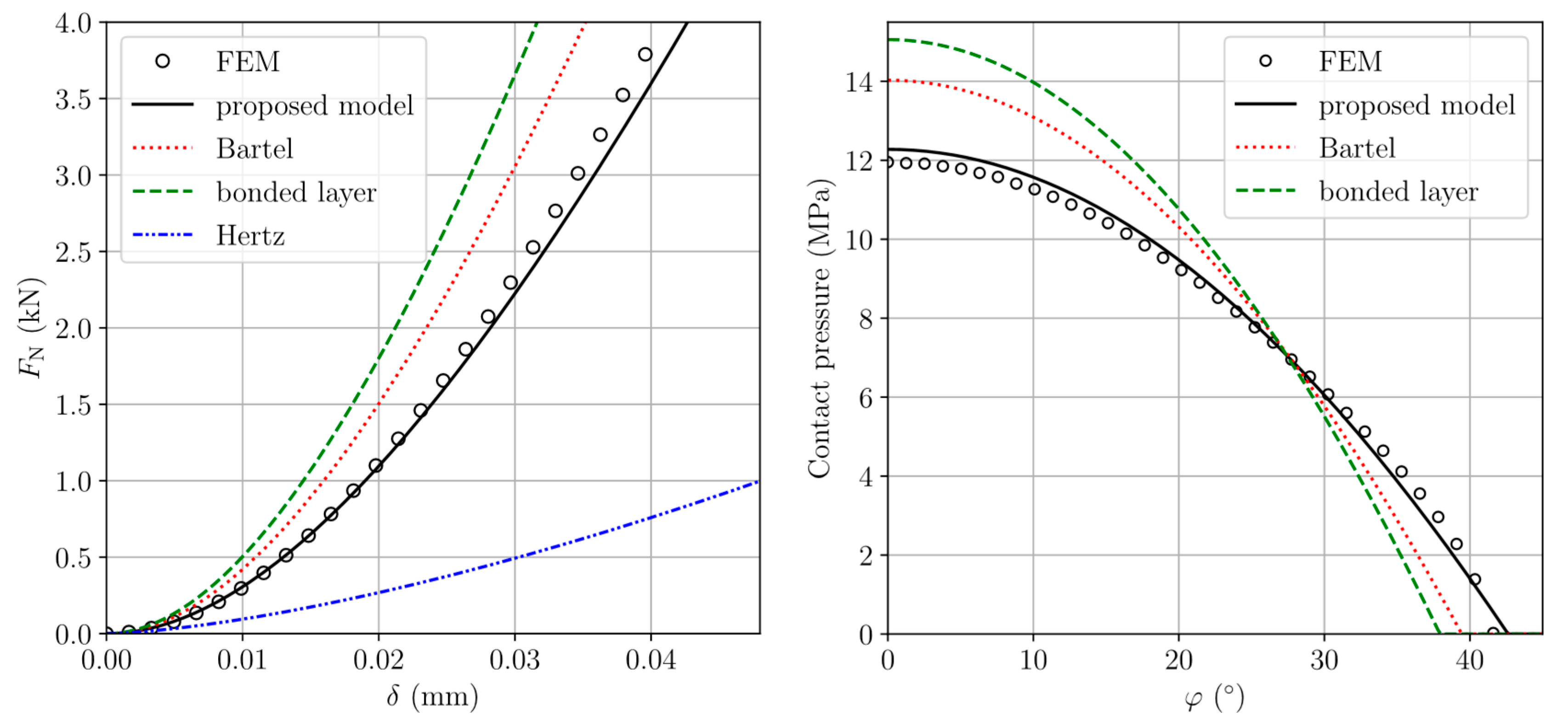
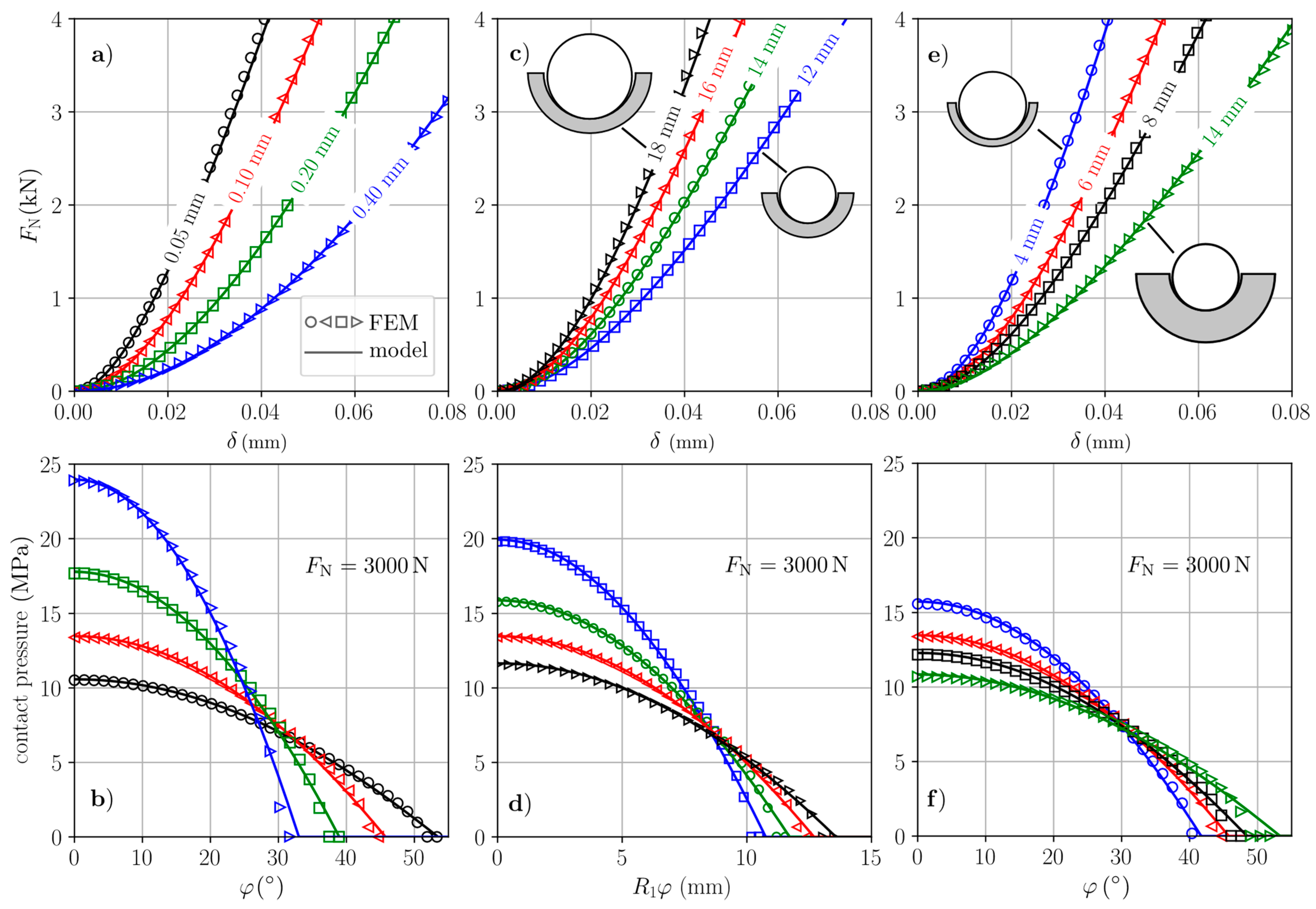
3.2. Results and Discussion

In this section, the solutions of the new analytical model are compared with the ones of the previously discussed models and finite element analysis. Furthermore, a parametric study is shown. All results presented comply with the geometrical and material properties listed in Table 1 and Table 2, respectively. In a first example, an inner cup radius of R 2 = 18   mm , a liner thickness of L = 6.75   mm , and a radial clearance of Δ R = 0.1   mm is chosen to clarify the influence of Poisson’s ratio.
Figure 3 shows the normal force in terms of normal displacement on the left for different models in comparison with the FEM solution for ν = 0.4 .
As expected, owing to the high degree of conformity, the Hertzian solution according to Equations (1)–(3) is not adequate for the investigated contact problem. For both the original model of Bartel et al. [16] and the bonded-layer-model (Note, that the analytical solution from the new model was used but with consideration of the bonded-layer-stiffness according to Equation (15)), deviations from the results of the finite element analysis are observable, but they are still within acceptable limits. The same applies to the pressure distribution as a function of angle illustrated on the right in Figure 3. The maximum pressure for both models is slightly higher than predicted by the FE simulations. On the other hand, the results with the new model considering the foundation modulus according to Equation (18) show excellent agreement with the FE results. Unfortunately, such an excellent agreement does not hold for a Poisson’s ratio of 0.45. As already discussed in the last section, this is a consequence of a small error accepting stiffness adjustment for higher Poisson’s ratios. Nevertheless, this leads to only minor deviations compared to the FE results, as demonstrated in Figure 4, which is why the model is well suited to represent the conformal contact even in the range of higher Poisson’s ratios.
It is also evident from Figure 4 that both the model of Bartel et al. and the bonded-layer-model produce results that differ significantly from the FE results. Both models react considerably stiffer and overestimate the maximum pressure by 17% and 25%, respectively.
In the following, the results obtained from the new model are compared with results of the FE analysis for common geometries of hip joint implants summarized in Table 1. A Poisson’s ratio of 0.4 is assumed. Figure 5 shows the normal force in terms of displacement, as well as the contact pressure distribution at 3000 N in comparison with FEM results for a variety of geometries. In all cases, and for both normal force and pressure distribution, the agreement with the FEM solution is very good. Only for the contact angle is a mentionable difference found as the model predictions are generally 3–8% larger than the FEM results.
As shown in Figure 5a,b, increasing the clearance decreases the contact stiffness and contact angle while increasing the maximum contact pressure. Figure 5c,e show that the overall contact stiffness is increased by increasing the head radius at constant liner thickness and decreasing the liner thickness at constant head radius.
In Figure 6, the trends with respect to the maximum contact pressure and the contact area can be studied more thoroughly. Both were calculated at a normal force of 3000 N for geometries within the limitations listed in Table 1. The contact area can be determined from the head radius and the half-contact angle by
A = 2 π R 1 2 ( 1 cos ε ) .
The lowest contact pressures are achieved for large head radii with a moderate liner thickness. The opposite trend is found for the contact area, where smaller head radii in combination with thin liners give the lowest values.
In the design of the contact pairs in THA with soft UHMWPE cups, various factors must be taken into account. In addition to low wear rates, the avoidance of edge loading due to the inclination of the cup, the risk of dislocation, and the risk of cup fracture are some important criteria [31,32]. With the proposed analytical model, it is possible to investigate significant influencing factors especially regarding the wear rate.
Recent experimental investigations of polyethylene wear indicate that minimizing the contact area is more important for low wear rates than minimizing the contact pressure [31,32,33]. As shown in Figure 5 and Figure 6, this can be achieved either by using small head radii and small liner thicknesses or increasing the radial clearance. However, the latter option may be disadvantageous, as another major influence factors for wear, the lubrication film thickness, is reducing significantly for increasing clearances [13].
Of course, the proposed analytical model in the current form can only serve as a first assessment in the dimensioning for THA with respect to a given wear law. For a thorough design, important factors such as the inclination of the cup, a lubrication regime, and explicit wear calculations must be considered as well.

4. Conclusions

A new approximate model for the almost conformal, elastic contact between a sphere and a spherical cup was proposed and successfully adapted for hard-on-soft implants in hip arthroplasty. The advantages of the proposed model over the common, well-established approximate models are the following:
1.
It provides acceptable results regardless of the liner thickness and also for Poisson’s ratios larger than 0.45.
2.
It provides very simple closed-form analytical solutions for both the pressure distribution and the dependencies between macroscopic contact quantities.
To establish the first advantage, it was assumed a priori that the dimensionless foundation modulus is a second degree polynomial function of the ratio of the inner cup radius to the liner thickness and its coefficients were estimated for different Poisson’s ratios by means of FE analyses. At this point, it is important to emphasize once again that all existing models under these conditions accept considerable errors to some extent, which has been proven by our FE analyses.
The second advantage allows easy integration of the model into macrodynamic time-dependent simulations of multibody systems, for which either the stress distribution or, directly, the contact force as a function of indentation depth can be used. An extension of the model for linear viscoelastic materials is easy to implement, although the damping constant still has to be chosen appropriately. Furthermore, by knowing the closed-form analytical solution, the corresponding adhesive contact problem can be solved under certain assumptions, as well. In this way, for example, Ciavarella [34] derived an approximate solution for the hard-on-hard almost conformal, spherical contact and found bistable behavior. However, the employed methods were originally developed for non-conformal contacts and their applicability to almost conformal contacts is not self-evident. In a future study, it is intended to clarify this. Moreover, the predictions of the proposed model should be verified under more realistic conditions, including loading, lubrication, and friction during a gait cycle.

Author Contributions

Conceptualization, M.H.; methodology, M.H. and F.F.; validation, F.F.; and writing—original draft preparation, M.H. and F.F. All authors have read and agreed to the published version of the manuscript.

Funding

We acknowledge support by the German Research Foundation and the Open Access Publication Fund of TU Berlin.

Institutional Review Board Statement

Not applicable.

Informed Consent Statement

Not applicable.

Data Availability Statement

All data is available in manuscript.

Acknowledgments

We would like to thank Dennis Gadour for his cooperation in the context of his bachelor thesis from 2017. Here, the model was presented for the first time by one of the authors (M.H.) and some preliminary FE analyses were performed by Gadour.

Conflicts of Interest

The authors declare no conflict of interest.

Abbreviations

SymbolSymbol Name
aContact radius
AContact area
C1, C2, C3Coefficients for fitting foundation modulus
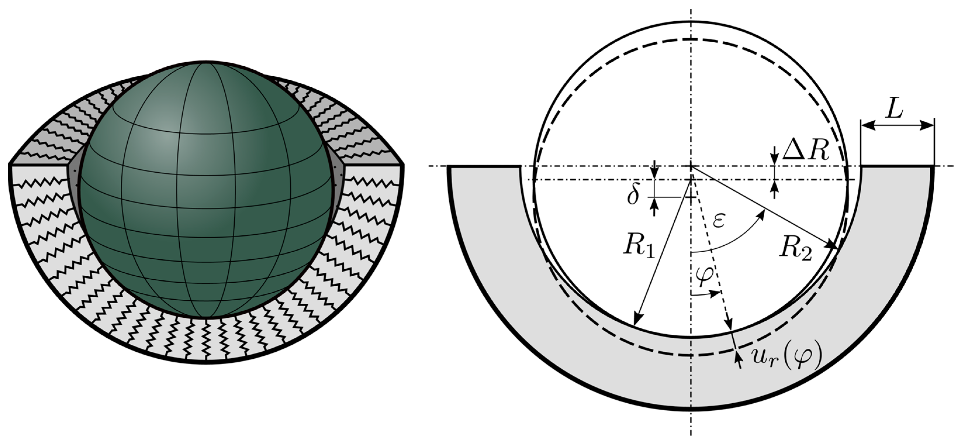
δContact/indentation depth
R Radial clearance
εHalf-contact angle
E1Elastic modulus of head material
E2, EElastic modulus of liner material
E * Effective elastic modulus
FNNormal force
KFoundation modulus
K ˜ Dimensionless foundation modulus
KBFoundation modulus introduced by Bartel et al.
KBLFoundation modulus of the bonded-layer-model
LLiner thickness
µCoefficient of friction
ν1Poisson ratio of head material
ν2, νPoisson ratio of liner material
p 0 Maximum contact pressure
p r Radial contact pressure
R 1 Radius of femoral head
R 2 Inner radius of acetabular cup
R * Effective radius of curvature
urRadial displacement of Winkler foundation

References

  1. Zhou, Z.R.; Jin, Z.M. Biotribology: Recent progresses and future perspectives. Biosurface Biotribol. 2015, 1, 3–24. [Google Scholar] [CrossRef] [Green Version]
  2. Arzt, E.; Quan, H.; McMeeking, R.M.; Hensel, R. Functional surface microstructures inspired by nature–From adhesion and wetting principles to sustainable new devices. Prog. Mater. Sci. 2021, 120, 100823. [Google Scholar] [CrossRef]
  3. Ruggiero, A.; Sicilia, A. Lubrication modeling and wear calculation in artificial hip joint during the gait. Tribol. Int. 2020, 142, 105993. [Google Scholar] [CrossRef]
  4. Basdogan, C.; Giraud, F.; Levesque, V.; Choi, S. A review of surface haptics: Enabling tactile effects on touch surfaces. IEEE Trans. Haptics 2020, 13, 450–470. [Google Scholar] [CrossRef]
  5. Vakis, A.I.; Yastrebov, V.A.; Scheibert, J.; Nicola, L.; Dini, D.; Minfray, C.; Ciavarella, M. Modeling and simulation in tribology across scales: An overview. Tribol. Int. 2018, 125, 169–199. [Google Scholar] [CrossRef]
  6. Heß, M. Über die Exakte Abbildung Ausgewählter Dreidimensionaler Kontakte auf Systeme mit Niedrigerer Räumlicher Dimension. Ph.D. Thesis, Technische Universität Berlin, Göttingen, Germany, 2011. [Google Scholar]
  7. Popov, V.L.; Heß, M. Method of Dimensionality Reduction in Contact Mechanics and Friction; Springer: Berlin/Heidelberg, Germany, 2015; ISBN 978-3-642-53875-9. [Google Scholar]
  8. Argatov, I.; Heß, M.; Popov, V.L. The extension of the method of dimensionality reduction to layered elastic media. ZAMM J. Appl. Math. Mech. Z. Für Angew. Math. Und Mech. 2018, 98, 622–634. [Google Scholar] [CrossRef]
  9. Dimaki, A.V.; Dmitriev, A.I.; Chai, Y.S.; Popov, V.L. Rapid simulation procedure for fretting wear on the basis of the method of dimensionality reduction. Int. J. Solids Struct. 2014, 51, 4215–4220. [Google Scholar] [CrossRef] [Green Version]
  10. Forsbach, F. Stress Tensor and Gradient of Hydrostatic Pressure in the Half-Space Beneath Axisymmetric Bodies in Normal and Tangential Contact. Front. Mech. Eng. 2020, 6, 39. [Google Scholar] [CrossRef]
  11. Persson, A. On the Stress Distribution of Cylindrical Elastic Bodies in Contact; Chalmers University of Technology: Göteborg, Sweden, 1964. [Google Scholar]
  12. Goodman, L.E.; Keer, L.M. The contact stress problem for an elastic sphere indenting an elastic cavity. Int. J. Solids Struct. 1965, 1, 407–415. [Google Scholar] [CrossRef]
  13. Di Puccio, F.; Mattei, L. Biotribology of Artificial Hip Joints. World J. Orthop. 2015, 6, 77–94. [Google Scholar] [CrossRef]
  14. Ferguson, R.J.; Palmer, A.J.; Taylor, A.; Porter, M.L.; Malchau, H.; Glyn-Jones, S. Hip replacement. Lancet 2018, 392, 1662–1671. [Google Scholar] [CrossRef]
  15. Jin, Z.M. A general axisymmetric contact mechanics model for layered surfaces, with particular reference to artificial hip joint replacements. Proc. Inst. Mech. Eng. Part H J. Eng. Med. 2000, 214, 425–435. [Google Scholar] [CrossRef]
  16. Bartel, D.L.; Burstein, A.H.; Toda, M.D.; Edwards, D.L. The effect of conformity and plastic thickness on contact stresses in metal-backed plastic implants. J. Biomech. Eng. 1985, 107, 193–199. [Google Scholar] [CrossRef]
  17. Imado, K.; Kido, Y.; Miyagawa, H. A method of calculation for contact pressure between femoral head and cup of artificial hip joint. Tribol. Trans. 2005, 48, 230–237. [Google Scholar] [CrossRef]
  18. Jin, Z.M.; Dowson, D.; Fisher, J. A parametric analysis of the contact stress in ultra-high molecular weight polyethylene acetabular cups. Med. Eng. Phys. 1994, 16, 398–405. [Google Scholar] [CrossRef]
  19. An, K.N.; Himeno, S.; Tsumura, H.; Kawai, T.; Chao, E.Y.S. Pressure distribution on articular surfaces: Application to joint stability evaluation. J. Biomech. 1990, 23, 1013–1020. [Google Scholar] [CrossRef]
  20. Bei, Y.; Fregly, B.J. Multibody dynamic simulation of knee contact mechanics. Med. Eng. Phys. 2004, 26, 777–789. [Google Scholar] [CrossRef] [PubMed] [Green Version]
  21. Abraham, C.L.; Maas, S.A.; Weiss, J.A.; Ellis, B.J.; Peters, C.L.; Anderson, A.E. A new discrete element analysis method for predicting hip joint contact stresses. J. Biomech. 2013, 46, 1121–1127. [Google Scholar] [CrossRef] [PubMed] [Green Version]
  22. Smith, C.R.; Won Choi, K.; Negrut, D.; Thelen, D.G. Efficient computation of cartilage contact pressures within dynamic simulations of movement. Comput. Methods Biomech. Biomed. Eng. Imaging Vis. 2018, 6, 491–498. [Google Scholar] [CrossRef]
  23. Askari, E.; Andersen, M.S. A closed-form formulation for the conformal articulation of metal-on-polyethylene hip prostheses: Contact mechanics and sliding distance. Proc. Inst. Mech. Eng. Part H J. Eng. Med. 2018, 232, 1196–1208. [Google Scholar] [CrossRef] [PubMed] [Green Version]
  24. Johnson, K.L. Contact Mechanics; Cambridge University Press: Cambridge, UK, 1985. [Google Scholar]
  25. Liu, C.S.; Zhang, K.; Yang, L. Normal force-displacement relationship of spherical joints with clearances. J. Comput. Nonlinear Dyn. 2006, 1, 160–267. [Google Scholar] [CrossRef]
  26. Revell, P.A. Joint Replacement Technology; Elsevier: Amsterdam, The Netherlands, 2014. [Google Scholar]
  27. Plank, G.R.; Estok, D.M.; Muratoglu, O.K.; Oconnor, D.O.; Burroughs, B.R.; Harris, W.H. Contact stress assessment of conventional and highly crosslinked ultra high molecular weight polyethylene acetabular liners with finite element analysis and pressure sensitive film. J. Biomed. Mater. Res. Part B Appl. Biomater. 2006, 80, 1–10. [Google Scholar] [CrossRef]
  28. Kurtz, S.M.; Villarraga, M.L.; Herr, M.P.; Bergström, J.S.; Rimnac, C.M.; Edidin, A.A. Thermomechanical behavior of virgin and highly crosslinked ultra-high molecular weight polyethylene used in total joint replacements. Biomaterials 2002, 23, 3681–3697. [Google Scholar] [CrossRef]
  29. Kurtz, S.M. 1-A primer on UHMWPE. In UHMWPE Biomaterials Handbook: Ultra-High Molecular Weight Polyethylene in Total Joint Replacement and Medical Devices; Andrew, W., Ed.; Elsevier: Amsterdam, The Netherlands, 2016; pp. 1–6. [Google Scholar]
  30. Li, G.; Sakamoto, M.; Chao, E.Y. A comparison of different methods in predicting static pressure distribution in articulating joints. J. Biomech. 1997, 30, 635–638. [Google Scholar] [CrossRef]
  31. Liu, F.; Galvin, A.; Jin, Z.; Fisher, J. A new formulation for the prediction of polyethylene wear in artificial hip joints. Proc. Inst. Mech. Eng. Part H J. Eng. Med. 2010, 225, 16–24. [Google Scholar] [CrossRef]
  32. Saikko, V. Effect of contact area on the wear and friction of UHMWPE in circular translation pin-on-disk tests. ASME J. Tribol. 2017, 139, 061606. [Google Scholar] [CrossRef]
  33. Mazzucco, D.; Spector, M. Effects of contact area and stress on the volumetric wear of ultrahigh molecular weight polyethylene. Wear 2003, 254, 514–522. [Google Scholar] [CrossRef]
  34. Ciavarella, M. A JKR solution for a ball-in-socket contact geometry as a bi-stable adhesive system. Acta Mech. 2018, 229, 2835–2842. [Google Scholar] [CrossRef] [Green Version]
Figure 1. A rigid ball indenting a radial directed Winkler foundation of a spherical cup: Three-dimensional view (left), sectional view including kinematics of contact (right).
Applsci 11 11170 g001
Figure 2. Dimensionless foundation modulus p 0 R 2 / δ E as a function of normal force F N (left), radial clearance Δ R (middle), and ratio of inner cup radius to liner thickness R 2 / L (right) for different Poisson’s ratios as determined by FEM. Dotted lines show the fitted dimensionless foundation modulus K ˜ used in the model with the constants listed in Table 3.
Applsci 11 11170 g002
Figure 3. Comparison of the FEM solutions with Hertzian theory, Bartel’s analysis, results from the bonded-layer-model, and the new proposed model, respectively, for a Poisson’s ratio of 0.4, inner cup radius 18 mm, clearance 0.1 mm, and liner thickness 6.75 mm: normal force as a function of indentation depth (left), and pressure distribution as a function of angular coordinate for a normal force of 3000 N (right).
Applsci 11 11170 g003
Figure 4. Comparison of the FEM solutions with Hertzian theory, Bartel’s analysis, results from the bonded-layer-model, and the new proposed model, respectively, for a Poisson’s ratio of 0.45, inner cup radius 18 mm, clearance 0.1 mm, and liner thickness 6.75 mm: normal force as a function of indentation depth (left), and pressure distribution as a function of angular coordinate for a normal force of 3000 N (right).
Applsci 11 11170 g004
Figure 5. Comparison of the normal force F N against normal displacement δ and contact pressure against angular coordinate φ or half arc length R 1 φ relations between FEM solution and analytical model. (a,b) different radial clearances Δ R with R 1 = 16   mm and L = 6   mm , (c,d) different head radii R 1 with Δ R = 0.1 mm and L = 6   mm , and (e,f) different liner thicknesses L with Δ R = 0.1   mm and R 1 = 16   mm .
Applsci 11 11170 g005
Figure 6. Maximum contact pressure (left) and contact area (right) in terms of head radius R 1 and liner thickness L at normal force F N = 3000   N and radial clearance Δ R = 0.1   mm . Dotted lines mark the commonly found lower and upper limit of the outer cup radius R 2 + L R 1 + L ; 16 mm and 26 mm (see Table 1).
Applsci 11 11170 g006
Table 1. Geometrical properties in THA [13,26,27].
Head Radius
R 1
Liner Thickness
L
Radial Clearance
Δ R
Outer Cup Radius
R 2 + L
11–23 mm3–15 mm0.05–0.2 mm16–26 mm
Table 2. Material properties.
MaterialElastic Modulus (GPa)Poisson’s Ratio
Steel2300.3
UHMWPE10.4, 0.45
Table 3. Dimensionless bedding stiffness constants C { 1 3 } for different Poisson’s ratios.
ν = 0.3 ν = 0.35 ν = 0.4 ν = 0.45 ν = 0.49
C 1 1.141.101.060.990.96
C 2 0.971.071.231.511.79
C 3 0.040.060.090.160.33
Publisher’s Note: MDPI stays neutral with regard to jurisdictional claims in published maps and institutional affiliations.

