Article

Experimental Research on Braking Feedback and Taxiing Feedback System of New Energy Vehicles

Department of Mechanical and Electrical Information, Weifang University of Science and Technology, Shouguang 262799, China
*
Author to whom correspondence should be addressed.
Appl. Sci. 2021, 11(23), 11093; https://doi.org/10.3390/app112311093
Submission received: 25 September 2021 / Revised: 1 November 2021 / Accepted: 1 November 2021 / Published: 23 November 2021
(This article belongs to the Special Issue Sustainable Manufacturing Systems Using Big Data)

Abstract

:
This paper took a new energy vehicle feedback system as the research object, aiming to study the energy recovery law of the new energy vehicle under braking feedback and taxiing feedback conditions. Firstly, the braking energy feedback control strategy and different forms of taxiing energy feedback were studied. Then the integration and application of braking energy recovery system were carried out on a pure electric bus and a hybrid electric bus, with each vehicle model corresponding to different integration and test schemes, which provided a guarantee for the relevant test of real vehicle environments. Finally, relevant vehicle experiments were carried out to test the impact of superposition and coordination strategies on the contribution rate of braking energy recovery under a typical Chinese city bus circle and compared the difference in vehicle energy consumption with and without taxi feedback strategy. The test results showed that the coordinated braking energy recovery control strategy can make more effective use of the maximum torque that can be fed back by the motor, and the fuel consumption of the taxiing feedback mode was lower than that of the no taxiing feedback mode under different driving conditions.

1. Introduction

Due to the oil crisis and growing environmental awareness that continues to improve, the arrival of the era of new energy vehicles is highly valued by the society. However, their short driving range and insufficient endurance have become the main problems in the development of new energy vehicles [1,2].
According to current research, improving the short-distance driving ability and range of new energy vehicles is divided into the following three ways, one is to improve the quality of the battery [3], the second is to change the charging method of new energy vehicles so that the vehicle can be charged while it is running [4,5,6,7], and the third is the new energy recovery system [8].
The energy recovery system of new energy vehicles is divided into braking energy recovery and coasting energy recovery. In the braking process, the energy consumed by friction braking accounts for approximately 50% of the total driving energy of the car. Under urban operating conditions of more frequent braking and starting, effective recovery of braking energy can reduce the energy consumption of electric vehicles by approximately 15%, which can extend the driving distance of electric vehicles by 10% to 30% [9].
The braking feedback and coasting feedback are some of the most important technologies to extend its driving range and energy efficiency [10,11,12], According to the literature, through braking feedback and coasting feedback system, vehicle economy can be improved by 15% [13,14,15]. Braking feedback technology is to recycle the energy lost during braking to improve the cruising range and driving performance of new energy vehicles [16]. Coasting feedback is the energy recovery achieved by releasing the throttle. At present, in-depth research has been conducted on braking energy recovery and conclusions have been drawn. However, it is difficult to apply it in practice due to the lack of clear research on pure electric buses and hybrid buses. The research purpose of this article was to conduct an actual vehicle test to analyze the difference between superposition’s and coordinated vehicle braking’s energy recovery economic contribution rates and the difference in the economic contribution rates of the whole vehicle with or without the recovery of coasting energy.
At present, researchers, automobile manufacturers and component manufacturers all over the world have conducted research and development on the control and design of brake energy recovery systems [17]. In the research by Chen Lv, Hong Wang, Dongpu Cao, and others, a new type of sliding mode control based on high-precision hydraulic feedback modulation was proposed. An open-loop load pressure control based on the linear relationship between the pressure drop and the coil current under the critical opening equilibrium state of the valve was proposed [18]. In [19], an electro-hydraulic brake system developed by Toyota was successfully applied to hybrid vehicles. In [20], in order to promote the realization of transient fault prevention and the detection and mitigation at the node and system levels, a new transient fault tolerance method for BBW systems was proposed. In [21], the position pressure map estimation algorithm was introduced to study the vehicle brake by wire, and the control of the electro-hydraulic brake by wire system was proposed. In [22], the economic contribution rate of the brake energy recovery of the proportional relay valve pneumatic control module was slightly higher than that of the proportional relay valve. In [23], the feasibility of using bidirectional half-bridge DC converters as chargers and brush-reduced DC (BLDC) motors provided actual data on the components in a power scale of 10:1.
In summary, although the research on braking energy recovery energy management strategies has been extensive and in depth, further system analyses will be necessary for the integration and application of braking energy recovery systems on pure electric buses and hybrid buses.

2. New Energy Vehicle Feedback-Related Technology Research

2.1. Research on the Braking Feedback of New Energy Vehicles

According to current research, one of the most extensive and in-depth studies in the field of braking energy recovery is the energy management strategy. The goal is to improve the overall vehicle energy economy and to fully exploit the braking energy recovery potential while ensuring braking stability. For brake energy recovery, brake energy management companies want to use as much electric power as possible, but also need to consider the limitations of regulations, motor external characteristics, battery SoC and other factors in the strategy design.

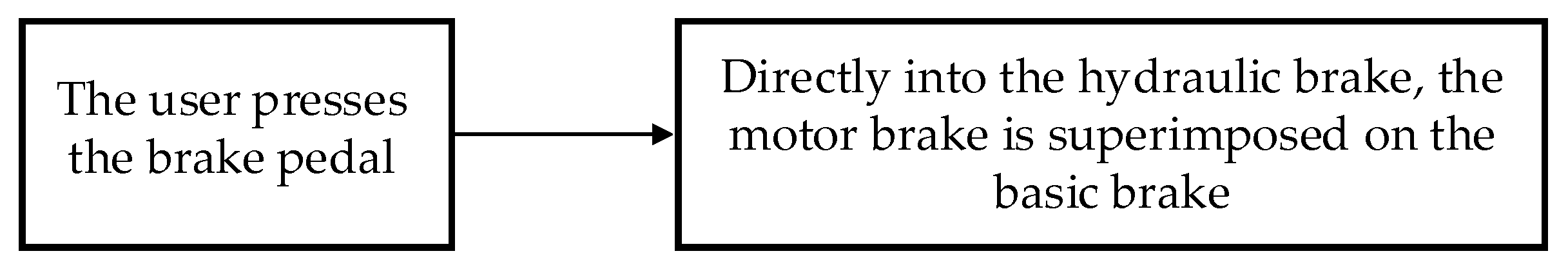
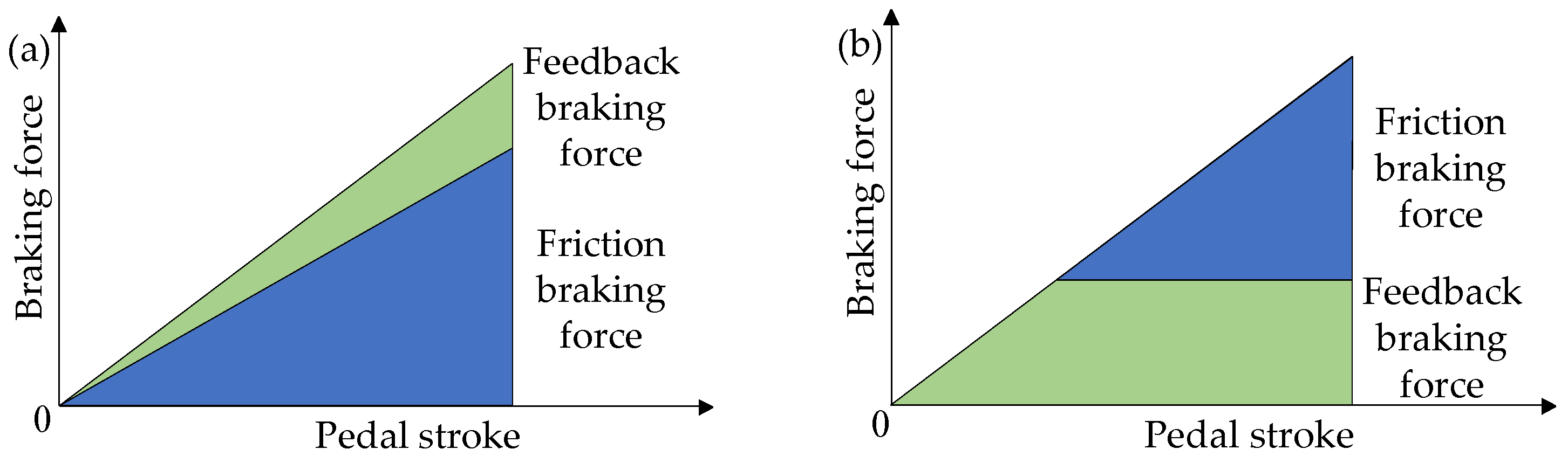
2.1.1. Stacking Type
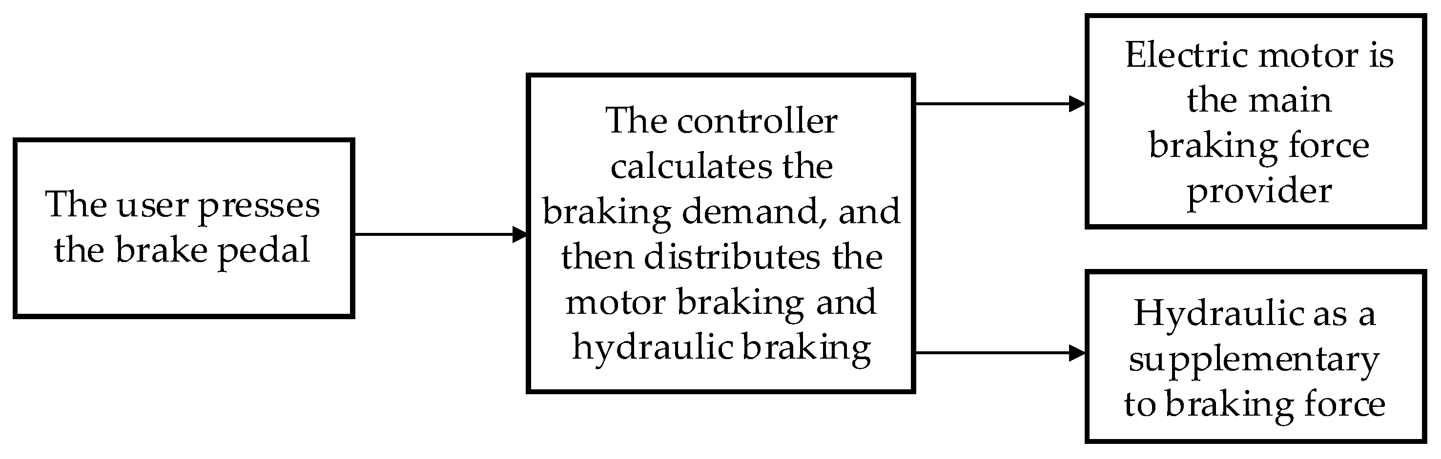
The superimposed brake energy recovery system superimposes the feedback braking force from the motor directly on the original friction braking force without adjusting the original friction braking force. As shown in Figure 1, the brake pedal and wheel brake cylinders are superimposed because they are coupled during deceleration; when the brake pedal is depressed, the wheel brake cylinders generate hydraulic pressure to apply the brakes, while the electric brake It is simply superimposed on the mechanical brake to complete the braking. This strategy is easy to implement and can be used directly with conventional braking systems. Only the control software setup is required and no new actuators need to be added, but it has inefficient feedback and poor braking feel.

2.1.2. Coordination

The principle of coordinated braking energy recovery strategy is to give priority to the use of feed-back braking force, while the hydraulic braking force is adjusted accordingly, so that the total braking demand is coordinated with the sum of the two braking forces. As shown in Figure 2, this strategy feed-back efficiency compared with the above-mentioned superposition strategy is more efficient, braking feeling is better, but the traditional hydraulic braking system needs to be redesigned or modified, the implementation is more complex. With the development of technology, coordinated feed-back braking, which has great advantages in many aspects such as feed-back efficiency, braking sensation and braking safety, has gradually become the mainstream of research and development.
Figure 3 shows the difference between superimposed and coordinated braking energy recovery system strategies. This strategy has a higher feedback efficiency and a better braking feeling, but it needs to be modified or redesigned for the traditional hydraulic braking system, which is more complicated to implement. With the development of technology, coordinated feedback braking, which has significant advantages in feedback efficiency, braking feel, and braking safety, has gradually become the mainstream in research and development.
From the above discussion, it can be seen that compared with the superimposed energy feedback control strategy, research on the coordinated energy feedback strategy shows great advantages in terms of braking efficiency and comfort. In the integration and application of a brake energy recovery system on a pure electric bus and a hybrid bus, it is still necessary to test and compare the difference in the economic contribution rates of braking energy recovery for the whole vehicle under different braking energy recovery control strategies.

2.2. Study of a New Energy Vehicle Coasting Feedback System

There are two types of energy recovery for electric vehicles, that is, braking energy recovery and coasting energy recovery, and the only criterion for differentiation is whether the brake pedal is pressed or not. Energy recovery that is achieved by pressing the brake pedal is braking energy recovery, and only relying on the loss of the throttle to achieve energy recovery is called coasting energy recovery.

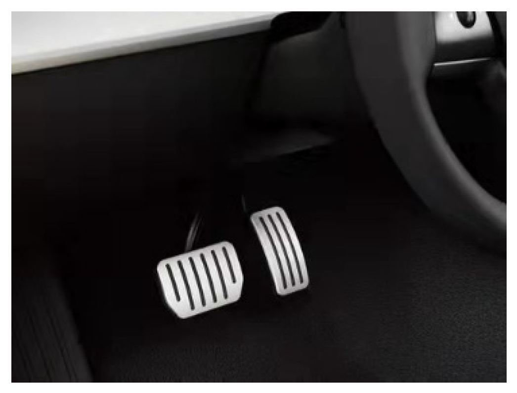
2.2.1. Double Pedal Control Type

The double pedal control type consists of a brake pedal and an accelerator pedal. As shown in Figure 4, the brake pedal is mainly used for deceleration and stopping, while the accelerator pedal, also known as the gas pedal, mainly controls the opening of the engine throttle, thus controlling the power output of the engine. When the accelerator pedal opening is fully released, the vehicle enters the coasting state and the coasting energy recovery system starts to work, and when the accelerator pedal is depressed, the coasting energy recovery system stops working. But this way cannot realize the adjustment of the energy recovery size by adjusting the accelerator pedal opening degree, and the energy recovery efficiency is low.

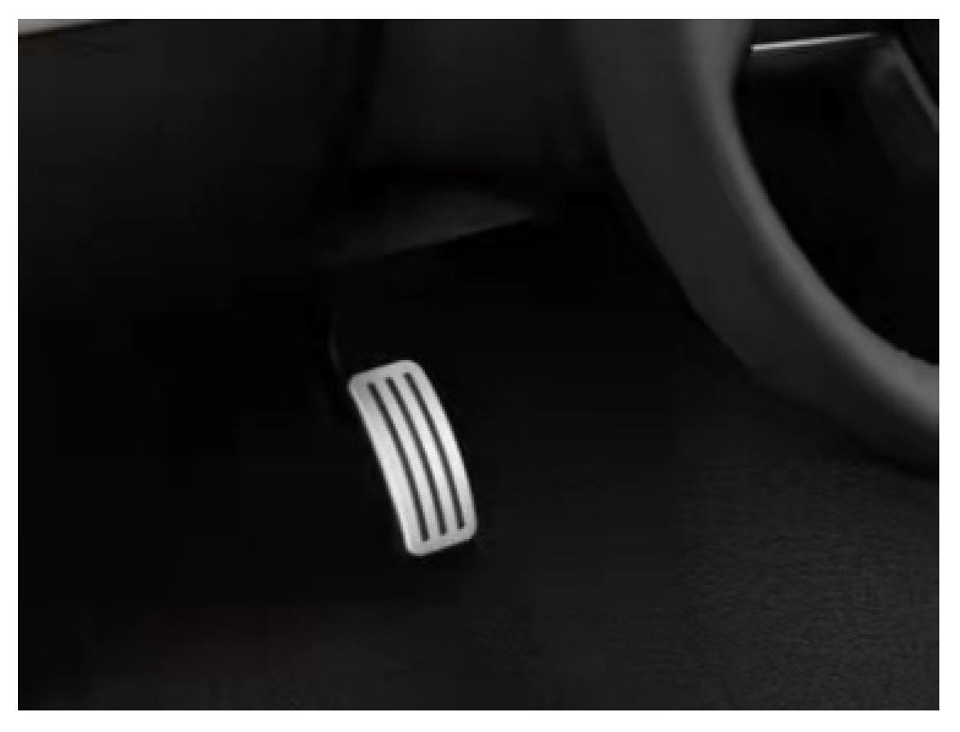
2.2.2. Single Pedal Control Type

The single pedal control type is actually also two pedals, namely, the brake pedal and the accelerator pedal, and the brake pedal is still mainly used to control deceleration and stopping, while the accelerator pedal is not only used to control the acceleration process of the vehicle but also to control the deceleration of the vehicle, that is, as shown in Figure 5, when the driver depresses the accelerator pedal, the vehicle accelerates to drive, and when the driver releases the accelerator pedal, the vehicle enters the deceleration state. This mode of a coasting energy recovery system occurs when the accelerator pedal is open less than a certain opening degree (the size of the opening degree is usually determined by the standard), and within a certain range of the accelerator pedal’s opening degree, the adjustment of the recovery energy size can be achieved; when the accelerator pedal is greater than this opening degree, the coasting energy recovery system stops working.
In the actual daily operation of a vehicle, the driver will sometimes perform a long-distance coasting driving process; considering the vehicle’s driving cycle conditions with a coasting phase, you can get a higher mileage as well as fuel economy contribution rate can be achieved, improving the actual driving regeneration recovery rate.
Conducting research on coasting energy return is important for the improvement of the economy of electric and new energy vehicles.

3. Complete Vehicle Integration and Test System for Brake Energy Recovery System

3.1. Test Subjects

In this paper, the integration and real-world tests of braking energy recovery systems were conducted for three vehicle models: a pure electric city bus, a fuel cell city bus, and a hybrid city bus [24]. Considering that the energy consumption of an air conditioner will affect the braking energy recovery due to the fact of unstable influencing factors, the test vehicles were examined without turning on their air conditioner [25].

3.1.1. Pure Electric City Bus

The pure electric bus test was based on an electric city bus of Foton. The power battery of this pure electric bus adopts Pryde’s lithium carbonate battery, which is composed of six 20 A-h capacity battery modules, and the axle adopts German ZF type axle.
The main technical parameters of the whole vehicle, including the motor and the battery are shown in Table 1.

3.1.2. Hybrid City Bus

A certain hybrid deep hybrid city bus of Yutong was the hybrid city bus used in this experiment. This bus adopts super capacitor as energy storage device, when the speed does not exceed 15 km/h, it adopts pure electric drive mode, that is, the internal combustion engine does not work and the vehicle drives by the electric motor, when the speed exceeds 15 km/h, the internal combustion engine drives the vehicle together with the electric motor.The parameters of the whole vehicle and the main technical parameters of important parts are shown in Table 2.

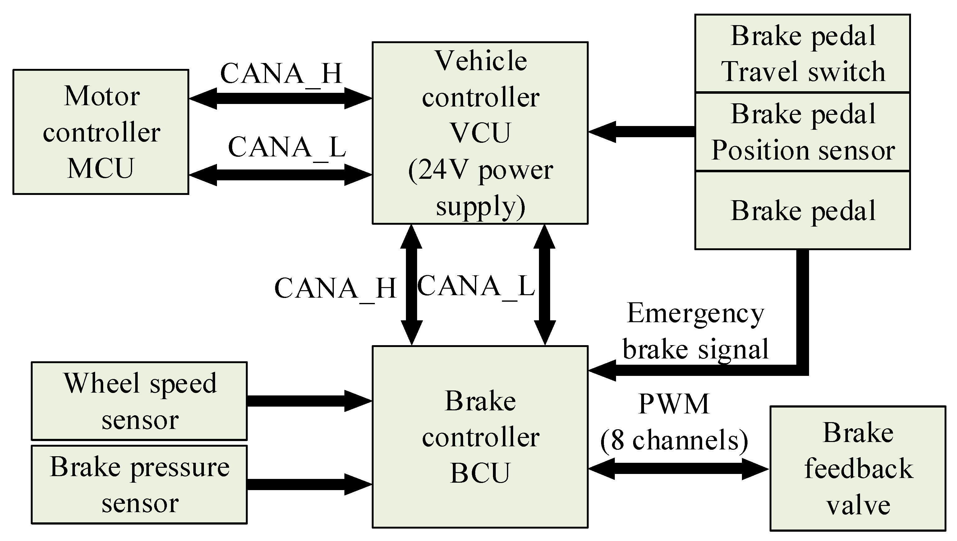
3.2. Brake Energy Recovery System Integrated into the Whole Vehicle

In the integration of a brake energy recovery system in a pure electric bus, while using the original vehicle controller (VCU), the brake energy recovery function and brake anti-lock function were integrated into one brake controller (BCU), and the CAN network was used to communicate between the controllers. The communication relationship and function division between the brake controller, vehicle controller and motor controller (MCU) are shown in Figure 6. Among them, CANA_H and CANA_L indicate that the VCU and MCU communicated through the CAN bus; A is the CAN bus A channel of the VCU. The BCU and signal control valve used an 8-channel PWM signal control, then the BCU signal control valve input used a 4-channel signal control valve for the BCU input 4- channel. The brake controller received the analog signal input from the sensors and the data, such as the brake pedal travel, front and rear axle air pressure values, real-time motor speed and torque, and the current status of the vehicle, were sent by the vehicle controller via the CAN bus, and send to the motor torque command value and the duty cycle command value of the feedback adjustment valve through the brake energy feedback control algorithm to the vehicle controller. The main functional modules of the brake controller included the solenoid drive module, wheel speed processing module, D/A and A/D modules, and the power supply module. The brake controller was shown in Figure 7.
A control unit containing the control algorithm was developed using a rapid prototype automatic code generation technology downloaded to the brake controller and applied to the test vehicle. The brake controller also had the functions of brake energy return control, hydraulic brake control and real-time communication with other controllers such as the vehicle controller and motor controller. The hardware system architecture of the controller was shown in Figure 7, which mainly included the microcontroller and its external circuit, signal acquisition circuit, driver circuit, fault diagnosis circuit and communication circuit.

3.3. Real Vehicle Test System

The test system of the hybrid bus brake energy recovery system test included the whole vehicle controller, brake controller, CAN data acquisition card, dSPACE system, driver assistant, laptop computer, fuel consumption meter, etc. In the hybrid bus, the braking energy feedback module was directly integrated into the vehicle controller, and the dSPACE was used to debug the braking energy recovery strategy, which allowed for online iterative modification of the model and algorithm parameters, greatly reducing the debugging cycle. The dSPACE system communicated with the vehicle controller in real time through the I/O expansion board [26].
Whole-vehicle fuel economy testing requires accurate measurements of whole-vehicle fuel consumption [27]. There are many hybrid bus energy subsystems, and the energy flow was complicated. If used in a working cycle to calculate the contribution of the energy economy of the whole vehicle, it was very complicated and needs the working cycle of fuel consumption, motor feedback torque and speed, super capacitor charging and discharging voltage, and other data, and there was a certain degree of error in the collected data [28]. In order to accurately examine the effect of the brake energy recovery system on the improvement of the fuel economy of the whole vehicle, the same vehicle, ensuring the same initial state, mainly, the same starting power of the supercapacitor and the starting power being lower than the threshold value of the maximum power that can be fed back, was tested on the same road section and under the same working conditions as the real vehicle with the brake energy recovery function turned off and the brake energy recovery system turned on, respectively [29]. Only the fuel consumption of the engine and the starting and ending voltages of the supercapacitor need to be collected. Compared with the battery, the instantaneous charging and discharging power of the supercapacitor was large, while the energy capacity was small. Under a suitable energy management strategy for the whole vehicle, a basically constant voltage for the supercapacitor can be achieved at the beginning and end of the cycle’s working condition. In the actual test, the energy change in the supercapacitor was two orders of magnitude smaller than the energy consumption of the whole vehicle in the cyclic condition, which can be negligible, so the engine fuel consumption can be directly used as the total energy consumption of the whole vehicle [30].

3.4. Brake Energy Recovery System Energy Economy Test Results

3.4.1. Comparison of Coordinated and Stacked Braking Energy Recovery Strategies

The energy economy was compared based on the energy recovery strategy in the previous section and the superimposed brake energy recovery strategy. The superimposed braking energy recovery strategy does not change the original air pressure braking based on the superimposed on the motor feedback braking torque, in order to get a better braking feeling, the motor feedback braking torque can not be too large. And in the coordinated braking energy recovery strategy, the maximum torque that can be fed back from the motor can be used effectively.
The braking process with an initial braking speed of 43.1 km/h and a braking deceleration of 0.58 m/s2 was selected, and the test results are shown in Figure 8 and Figure 9.
As can be seen from Figure 9, in the superimposed braking energy recovery strategy, the maximum braking torque of the motor was approximately 200 N·m, and the maximum battery charging current was approximately 100 A. In the coordinated braking energy recovery strategy, the braking torque of the motor can reach 500 N·m, and the battery charging current can reach more than 140 A, which greatly improves the braking energy recovery. The two braking energy recovery strategies were tested in a typical Chinese urban bus cycle, and the results are shown in Figure 10 and Figure 11.
The analysis of the test results calculates that the contribution of the coordinated strategy is 21.28% and the contribution of the stacked strategy is 14.57%. The test results can prove that the energy economy of the coordinated braking energy recovery strategy has a significant improvement over the stacked strategy.

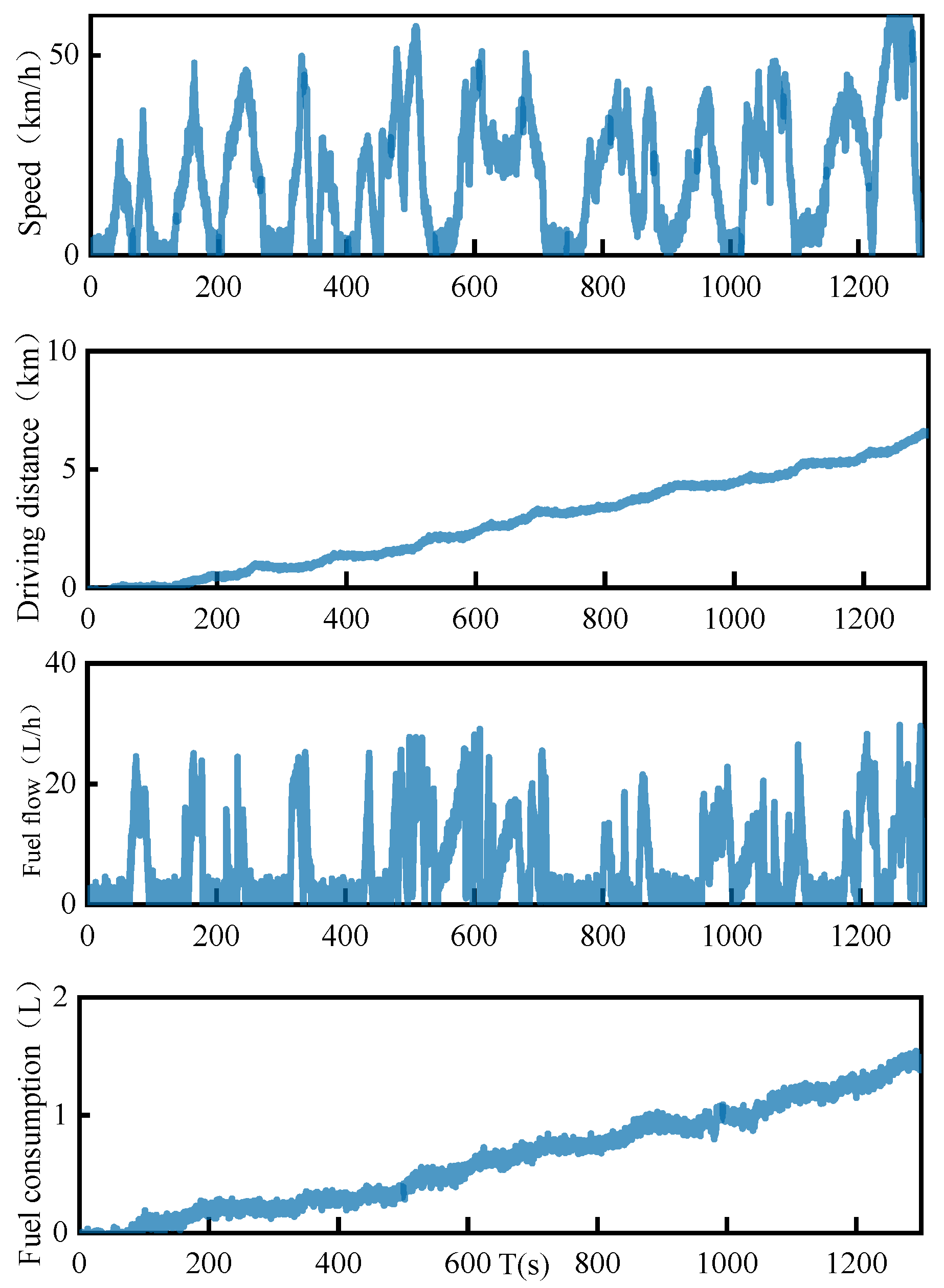
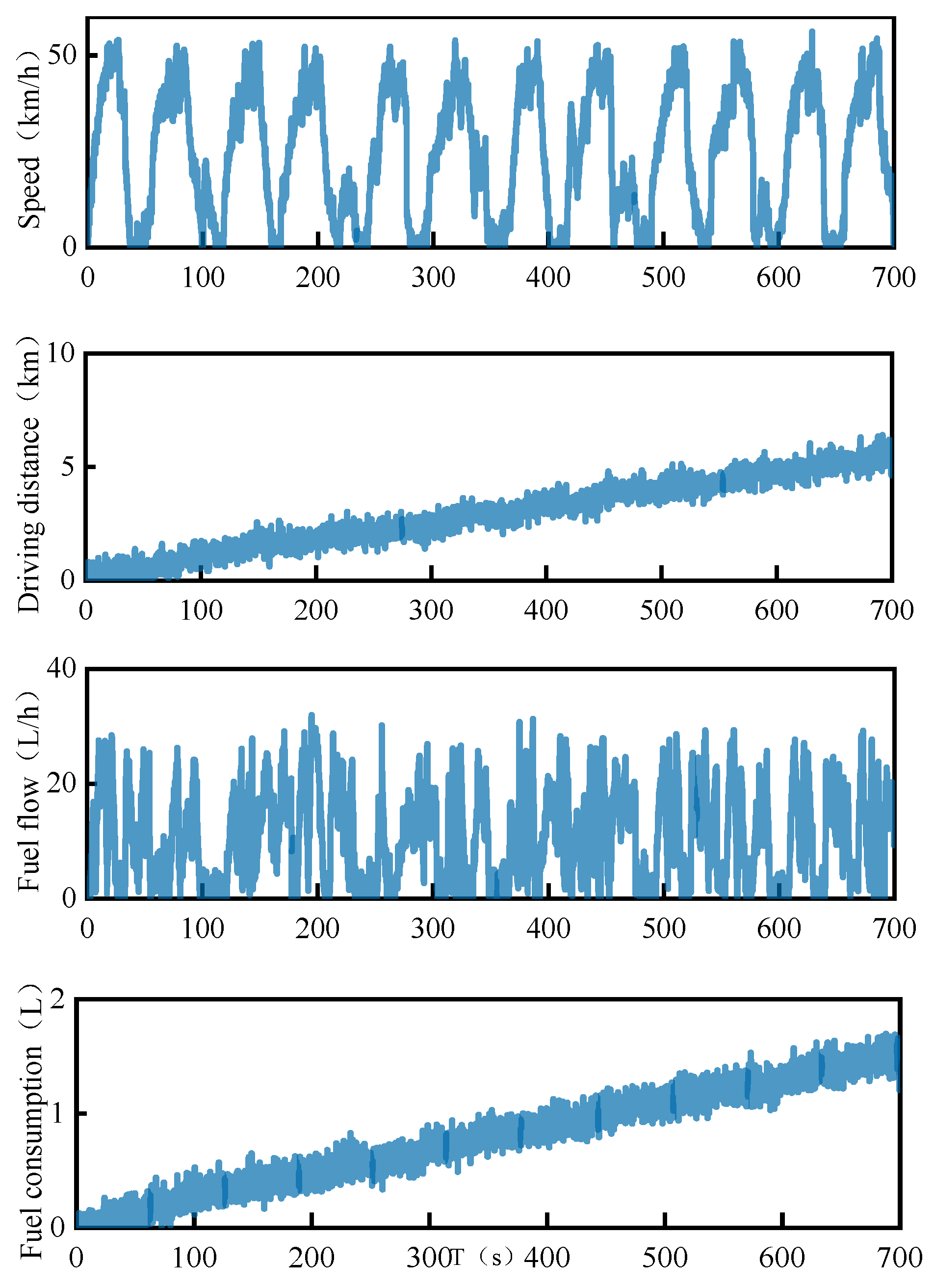
3.4.2. Comparison of the Coasting Braking Feedback Strategy and Pedal-Free Stroke Strategy

The coasting braking feedback strategy is to provide feedback braking force from the motor when the vehicle is coasting, i.e. when the accelerator pedal is released and the brake pedal travel does not exceed the mechanical free travel.
In the actual daily operation of the vehicle, the driver sometimes performs long distance coasting driving. Considering the vehicle driving cycle and coasting phase, Yutong develops Yutong working condition internal test according to the bus driving characteristics, which only stipulates the distance of each start-stop of the vehicle and does not stipulate the specific driving mode of the driver in the driving process. process for simply simulating the operation of the bus line at the stopping point [31]. The driver’s driving habits determine the speed of the vehicle at every moment and the time spent by the vehicle during acceleration, braking and coasting. In this case, the driver’s driving habit is usually to accelerate the vehicle to a certain speed by pressing the gas pedal (acceleration phase)—release the gas pedal to make the vehicle slide for a period of time (coasting phase)—press the brake pedal to slow the vehicle to a stop (braking phase). If motor braking is not performed in the coasting phase, then in the braking phase after the coasting phase, the driver is bound to increase the braking intention to stop the vehicle at the point specified in the working conditions, when the motor power may not be able to meet the total braking force demand, and pneumatic braking force is needed to compensate, thus consuming the kinetic energy of the braking process. If coasting braking feedback is introduced, the motor keeps braking during the vehicle coasting process and reaches the braking stage, the driver no longer needs excessive braking force to slow down the vehicle, thus reducing the pneumatic friction braking force in total braking and improving the utilization of braking energy [32].
Based on the hybrid city bus platform described in the previous section, fuel consumption tests were conducted for typical Chinese city bus cycle conditions, the Yutong conditions for the pedal-free travel recovery braking control strategy, and the recovery braking control strategy with coasting feedback. The results of the typical Chinese city bus cycle conditions and the Yutong conditions are shown in Figure 12, Figure 13, Figure 14 and Figure 15.
Figure 8 and Figure 9 show the working conditions of a typical city bus cycle in China. In a typical Chinese city bus cycle, the fuel consumption of the no-glide feedback strategy is 1.4 L, and the vehicle distance is 6.08 km; with the glide feedback strategy, the vehicle speed was not accelerated to 60 km/h in the last acceleration stage due to the road condition, and the distance was slightly shorter, 5.46 km, and the fuel consumption was 1.26 L.
Figure 14 and Figure 15 show the working conditions for the test of the Yutong working condition. It can be seen that since the Yutong condition is a cyclic condition based on the starting and stopping points, both had the same driving distance of 5.0 km, but the fuel consumption was significantly different. The fuel consumption of the braking energy recovery strategy without coasting feedback was approximately 1.8 L, while the fuel consumption of the braking energy recovery strategy with coasting feedback was only approximatelys 1.4 L [33].
The fuel consumption collected in the real vehicle test was divided by the vehicle distance and multiplied by one hundred to obtain the 100 km fuel consumption as shown in Table 3, and the fuel economy contribution rate was obtained by comparing the 100 km fuel consumption in the working condition test with the conventional internal combustion engine drive mode as shown in Table 4.
As can be seen from the above two tables, for typical urban bus conditions in China, the 100 km fuel consumptions of the no-glide feedback mode and the mode with glide feedback were very close, with a difference of approximately 0.4%, which is within the margin of error. For the Yutong working condition, due to the presence of a large number of coasting phases, the fuel consumption with coasting feedback mode was much lower than that without the coasting feedback mode [34], by approximately 20.8%, and the fuel economy contribution improved by approximately 17.3%.

4. Conclusions

In this thesis, an experimental study on braking feedback as well as taxiing feedback systems for new energy vehicles was conducted with the following main findings.
For stacked and coordinated brake energy recovery systems, a number of studies were conducted with and without glide feedbacks. The differences between a stacked and a coordinated system under the same operating conditions and on the same road sections were tested as well as the fuel economy contribution with and without the glide feedback system.
The integration and application of the braking energy recovery system in a purely electric bus was carried out, and the difference in the economic contribution of the braking energy recovery of the whole vehicle under different braking energy recovery control strategies was tested and compared. The results showed that the coordinated brake energy recovery control strategy can effectively utilize the maximum torque that can be fed back by the motor.
The integration and application of the braking energy recovery system was carried out on a hybrid bus, and the difference in the economic contribution of the vehicle under different cycle conditions with and without taxiing was tested and compared. The results showed that fuel consumption was reduced under different conditions in the skid feedback mode than without the skid feedback mode. In the case of the Yutong, for example, the fuel consumption was reduced by approximately 20.8%, and the fuel economy contribution increased by approximately 17.3% with a skid feedback mode than without a skid feedback mode.
In view of the developmental status and trends in the field of braking energy recovery and anti-skid control of new energy vehicles, combined with the research content and results of the subject, the research work of this paper can also be deepened and expanded upon from the following aspects.
  • The real vehicle verification of different models and driving conditions can be carried out under the different braking energy recovery control strategies and taxiing feedback strategies proposed in this paper. The effects of the superposition and coordinated braking energy feedback strategy and energy recovery strategy under taxiing condition on vehicle energy consumption can be further discussed;
  • In terms of hardware in the loop test bench, the pneumatic braking test bench and the electric drive system dynamics test bench can be integrated to be realized simultaneously in the loop test of a friction braking system and electric drive/braking system. It lays the foundation for further research on different strategies and schemes of electric vehicle energy recovery;
  • In addition, in the future, we are considering for the next step of testing the use of collected energy for the start of movement of those same vehicles to calculate how much petroleum fuel can be saved when certain cities reach 10%, 50%, or 90% of their hybrid bus fleets and to conduct a study on the total cost of oil and electricity;
  • Improving the range of new energy vehicles is not only about braking energy recovery and coasting energy recovery. Wireless charging, hybrid charging, and photovoltaic charging can also provide energy to the vehicle while it is running.

Author Contributions

Conception and writing of the original draft preparation, N.L.; assisted in implementing the research content of the paper, providing critical comments, Y.L.; visualization, S.T. All authors have read and agreed to the published version of the manuscript.

Funding

This research received no external funding.

Institutional Review Board Statement

Ethical review and approval were waived for this study due to the fact that this paper did not involve ethical issues.

Informed Consent Statement

Not applicable.

Data Availability Statement

The study did not involve important data.

Conflicts of Interest

The authors declare no conflict of interest.

References

  1. Liu, Y.S.; Tan, J.W. Green traffic-oriented heavy-duty vehicle emission characteristics of China VI based on portable emission measurement systems. IEEE Access 2020, 8, 106639–106647. [Google Scholar] [CrossRef]
  2. Liu, Y.S.; Ge, Y.S.; Tan, J.W.; Fu, M.L.; Asad, N.S.; Li, L.Q.; Ji, Z.; Ding, Y. Emission characteristics of offshore fishing ships in the Yellow Bo Sea, China. J. Environ. Sci. 2018, 65, 83–91. [Google Scholar] [CrossRef]
  3. Tan, X.M.; Li, T.Y. Analysis of challenges and opportunities in the development of new energy vehicle battery industry from the perspective of patents. IOP Conf. Ser. Earth Environ. Sci. 2021, 632, 032049. [Google Scholar] [CrossRef]
  4. Naoui, M.; Flah, A.; Zaafouri, I.; Mohit, B.; Ghoneim, S.S.M.; Mahrous, A. The impact of coil position and number on wireless system performance for electric vehicle recharging. Sensors 2021, 21, 4343. [Google Scholar] [CrossRef]
  5. Habib, K.; Aymen, F.; Naoui, M.; Majed, A.; Mohit, B.; Shailendra, M.; Naveen, K.S.; Sunil, K.S. Increasing electric vehicle autonomy using a photovoltaic system controlled by particle swarm optimization. IEEE Access 2021, 9, 72040–72054. [Google Scholar]
  6. Naoui, M.; Aymen, F.; Ben, H.M. Inductive charger efficiency under internal and external parameters variation for an electric vehicle in motion. Int. J. Powertrains 2019, 8, 343–358. [Google Scholar]
  7. Flah, A. Internal fuzzy hybrid charger system for a hybrid electrical vehicle. J. Energy Resour. Technol. 2018, 140, 12003–12008. [Google Scholar]
  8. Zhu, Y.Y.; Hao, W.; Zhen, C.C. Regenerative braking control under sliding braking condition of electric vehicles with switched reluctance motor drive system. Energy 2021, 230, 120901. [Google Scholar] [CrossRef]
  9. Han, T.L.; Zeng, B.; Tong, Y.J. Theoretical study on energy recovery rate of regenerative braking for hybrid mining trucks with different parameters. J. Energy Storage 2021, 42, 103127. [Google Scholar] [CrossRef]
  10. Zhang, J.Z.; Li, Y.T.; Lv, C.; Yuan, T. New regenerative braking control strategy for rear-driven electrified minivans. Energy Convers. Manag. 2014, 82, 135–145. [Google Scholar]
  11. Lv, C.; Zhang, J.Z.; Li, Y.T.; Sun, D.S.; Yuan, Y. Hardware-in-the-loop simulation of pressure-difference-limiting modulation of the hydraulic brake for regenerative braking control of electric vehicles. Proc. Inst. Mech. Eng. Part D J. Automob. Eng. 2014, 228, 649–662. [Google Scholar] [CrossRef]
  12. Mikolaj, B.; Marcin, P. Multiaspect measurement analysis of breaking energy recovery. Energy Convers. Manag. 2016, 127, 35–42. [Google Scholar]
  13. Tian, G.D.; Zhang, H.H.; Feng, Y.X.; Jia, H.F.; Zhang, C.Y.; Jiang, Z.G.; Li, Z.W.; Li, P.G. Operation patterns analysis of automotive components remanufacturing industry development in China. J. Clean. Prod. 2017, 164, 1363–1375. [Google Scholar] [CrossRef]
  14. Michael, P.; George, D.; Dennis, N.A. Development and use of a regenerative braking model for a parallel hybrid electric vehicle. SAE Pap. 2000, 14. [Google Scholar] [CrossRef]
  15. Samuel, F.; Jony, J.; Fabricio, L.S.; Ludmila, C.A.; Franco, G. Multi-objective optimization design and control of plug-in hybrid electric vehicle powertrain for minimization of energy consumption, exhaust emissions and artery degradation. Energy Convers. Manag. 2021, 234, 11309. [Google Scholar]
  16. Zhang, J.J.; Yang, Y.; Qin, D.T.; Fu, C.Y.; Cong, Z.P. Regenerative braking control method based on predictive optimization for four-wheel drive pure electric vehicle. IEEE Access 2020, 99, 1. [Google Scholar] [CrossRef]
  17. Tian, G.D.; Zhang, H.H.; Feng, Y.X.; Wang, D.Q.; Peng, Y.; Jia, H.F. Green decoration materials selection under interior environment characteristics: A grey-correlation based hybrid MCDM method. Renew. Sustain. Energy Rev. 2018, 81, 682–692. [Google Scholar] [CrossRef]
  18. Lv, C.; Wang, H.; Cao, D.P. High-precision hydraulic pressure control based on linear pressure-drop modulation in valve critical equilibrium state. IEEE Trans. Ind. Electron. 2017, 64, 7984–7993. [Google Scholar] [CrossRef] [Green Version]
  19. Eiji, N.; Masayuki, S.; Akira, S.; Akihiro, O.; Toshikazu, K. Development of electronically controlled brake system for hybrid vehicle. SAE Tech. Pap. 2002, 8. [Google Scholar] [CrossRef]
  20. Huang, S.; Zhou, C.J.; Yang, L.L.; Qin, Y.Q.; Huang, X.F.; Hu, B.W. Transient fault tolerant control for vehicle brake-by-wire systems. Reliab. Eng. Syst. Saf. 2016, 149, 148–163. [Google Scholar] [CrossRef]
  21. Fabio, T.; Matteo, C.; Giulio, P.; Sergio, M.S. Adaptive position–pressure control of a brake by wire actuator for sport motorcycles. Eur. J. Control 2014, 20, 79–86. [Google Scholar]
  22. Li, N.; Zhang, J.Z.; Li, C.; Gou, J.F.; Liu, Y.S. Research on the influence of the proportional ralve on the economy and safety of the electric bus through the braking energy recovery system. Energy Sources Part A Recovery Util. Environ. Eff. 2019, 10, 25–30. [Google Scholar]
  23. Nitesh, K.S.; Chaitali, K.; Sadhan, G. An implementation perspective of hybrid electric vehicle. J. Inf. Optim. Sci. 2019, 40, 1693–1708. [Google Scholar]
  24. Liu, Y.S.; Ge, Y.S.; Tan, J.W.; Wang, H.L.; Ding, Y. Research on ammonia emissions characteristics from light-duty gasoline vehicles. J. Environ. Sci. 2021, 106, 182–193. [Google Scholar] [CrossRef]
  25. Li, N.; Zhang, J.Z.; He, C.K. Research on the influence of air conditioning energy consumption on brake energy recovery contribution rate based on operating conditions. IOP Conf. Ser. Earth Environ. Sci. (EES) 2021, 2, 1–5. [Google Scholar] [CrossRef]
  26. José, H.; Luis, Q.; Michael, G.; Jenny, D. Comparison of three methods for constructing real driving cycles. Energies 2019, 12, 665. [Google Scholar] [CrossRef] [Green Version]
  27. Liu, Y.S.; Wang, H.L.; Li, N.; Tan, J.W.; Chen, D. Research on ammonia emissions from three-way catalytic converters based on small sample test and vehicle test. Sci. Total Environ. 2021, 795, 148926. [Google Scholar] [CrossRef]
  28. Francesc, C.; Roberto, Á.F. Predictive model for energy consumption of battery electric vehicle with consideration of self-uncertainty route factors. J. Clean. Prod. 2020, 276, 124–188. [Google Scholar]
  29. Zhao, X.; Ye, Y.M.; Ma, J.; Shi, P.L.; Chen, H. Construction of electric vehicle driving cycle for studying electric vehicle energy consumption and equivalent emissions. Environ. Sci. Pollut. Res. 2020, 27, 37395–37409. [Google Scholar] [CrossRef]
  30. Tian, G.D.; Liu, Y.M.; Ke, H.; Chu, J.G. Energy evaluation method and its optimization models for process planning with stochastic characteristics: A case study in disassembly decision-making. Comput. Ind. Eng. 2012, 63, 553–563. [Google Scholar] [CrossRef]
  31. Wawrzyniec, G.; Maciej, L. Theoretical analysis of electric vehicle energy consumption according to different driving cycles. IOP Conf. Ser. Mater. Sci. Eng. 2018, 23, 11–22. [Google Scholar]
  32. Li, N.; Zhang, J.Z.; Zhang, S.Y.; Hou, X.H.; Liu, Y.H. The influence of accessory energy consumption on evaluation method of braking energy recovery contribution rate. Energy Convers. Manag. 2018, 166, 545–555. [Google Scholar] [CrossRef]
  33. Tian, G.D.; Chu, J.W.; Liu, Y.M.; Ke, H.; Zhao, X.; Xu, G. Expected energy analysis for industrial process planning problem with fuzzy time parameters. Comput. Chem. Eng. 2011, 35, 2905–2912. [Google Scholar] [CrossRef]
  34. Sun, H.; Liu, Y.S.; Tan, J.W. Research on Testing Method of Oil Characteristic Based on Quartz Tuning Fork Sensor. Appl. Sci. 2021, 11, 5642. [Google Scholar] [CrossRef]
Figure 1. Working principle of a superimposed brake energy recovery.
Applsci 11 11093 g001
Figure 2. Coordinated brake energy recovery principle of operation.
Applsci 11 11093 g002
Figure 3. (a) Superposition braking energy recovery system, (b) coordinated braking energy recovery system.
Applsci 11 11093 g003
Figure 4. Double pedal type.
Applsci 11 11093 g004
Figure 5. Single pedal type.
Applsci 11 11093 g005
Figure 6. Communication relationship diagram of each controller.
Applsci 11 11093 g006
Figure 7. Hardware architecture of the brake controller.
Applsci 11 11093 g007
Figure 8. Coordinated braking energy recovery strategy for a particular braking process.
Applsci 11 11093 g008
Figure 9. Stacked brake energy recovery strategy for a particular braking process.
Applsci 11 11093 g009
Figure 10. Coordinated braking energy recovery strategy cycling condition test.
Applsci 11 11093 g010
Figure 11. Cyclic tests of the stacked brake energy recovery strategy.
Applsci 11 11093 g011
Figure 12. Typical urban bus cycle conditions in China (no taxiing feedback).
Applsci 11 11093 g012
Figure 13. The typical Chinese city bus circle driving conditions (with taxiing feedback).
Applsci 11 11093 g013
Figure 14. Yutong driving conditions (no taxiing feedback).
Applsci 11 11093 g014
Figure 15. Yutong driving conditions (with taxiing feedback).
Applsci 11 11093 g015
Table 1. Main parameters of the pure electric bus.
ParameterParameter Value and Unit
Curb weight12,400 kg
Full load quality18,000 kg
Motor rated power100 kw
Main reducer reduction ratio6.2
Battery capacity120 A·h
Maximum charging rate4 C
Speed69 km/h
Power150 kw
Table 2. Main parameters of the hybrid bus.
ParameterParameter Value and Unit
Curb quality12,000 kg
Full load quality18,000 kg
Motor rated power60 kw
Motor rated torque820 N·m
Main reducer reduction ratio6.166
Maximum voltage of super capacitor550 V
Super capacitor capacity165 F
Speed69 km/h
Power170 kw
Table 3. Hybrid electric bus fuel consumption per 100 km.
Working ConditionFuel Consumption per Hundred Kilometers (L/100 km)
Traditional Internal Combustion EngineBraking Energy RecoveryBraking Energy Recovery
DriveNo Taxiing FeedbackTaxiing Feedback
China’s typical city37.0423.0223.49
bus conditions
Yutong working conditions38.5332.0325.34
Table 4. Fuel economy contribution rate.
Working ConditionFuel Consumption
per Hundred Kilometers (L/100 km)
No Taxiing FeedbackTaxiing Feedback
China’s typical city37.85%36.58%
bus conditions
Yutong working conditions16.87%34.23%
Publisher’s Note: MDPI stays neutral with regard to jurisdictional claims in published maps and institutional affiliations.

