Article

Pressure Loss in Ducts by Dissipative Splitter Silencers: Comparative Study of Standardized, Numerical and Experimental Results

by
Bartosz Chmielewski
*,
Iván Herrero-Durá
* and
Paweł Nieradka
KFB Acoustics Sp. z o. o. Mydlana 7, 51-502 Wrocław, Poland
*
Authors to whom correspondence should be addressed.
Appl. Sci. 2021, 11(22), 10998; https://doi.org/10.3390/app112210998
Submission received: 22 October 2021 / Revised: 10 November 2021 / Accepted: 17 November 2021 / Published: 20 November 2021

Abstract

:
Dissipative splitter silencers are widely used in industry for the reduction of propagated sound waves in ducts. Even though these systems are effective from the acoustics point of view when they are properly designed, they also introduce a pressure loss in the system, due to the modification of the properties of the flow circulating inside the duct. This effect is not desired in some industrial applications, so it is necessary to be able to predict the pressure loss as precisely as possible to design silencers according to the needs. Nevertheless, the prediction made by standards are usually limited to given geometries or flow speed. In this work, we present a comparative study on the results obtained for the pressure loss by means of the standards ISO 14163 and VDI 1801-1, numerical simulations with the finite element method, and experimental measurements. Additionally, two different profile shapes and four input face velocities are tested in order to know the influence of these parameters in the variations of the flow and the accuracy of the prediction of the different methods.

1. Introduction

Dissipative splitter silencers are the most used mechanical dissipative silencers in industry [1]. These systems are used for a wide variety of applications in different fields of industry, such as noise control in fans [2], vehicles [3,4] and gas turbine engines [5], among many others. Although they have been studied and developed for decades [6,7,8], splitter silencers are still under study, as demonstrated by the analytical model presented by Venegas et al. in 2018 [9] in which the homogenization-based theory of sound propagation in heterogeneous media is used to derive the effective acoustic parameters of various types of silencers. Some recent works additionally introduce the possibility of a hybrid approach with active and passive silencers for noise control [10]. Consequently, the challenge nowadays is optimizing the design of silencers to maximize their efficiency in given applications [11].
Dissipative splitter silencers usually consist of a bulk reacting porous material with a given cross section and a perforated plate that protects this material from the conditions in the duct in which a low Mach number flow circulates [12]. This configuration provides them with good performance and effectiveness in the reduction of the propagated sound waves in ducts and, at the same time, simplifies their design and reduces the manufacturing costs. Nevertheless, despite the good performance of splitter silencers for acoustic purposes, placing these devices in ducts reduces the cross-section available for the circulation of air and flow. In those cases in which the flow is circulating through the duct, this leads to the modification of the local behavior of the duct in the vicinity of the silencers.
Pressure loss is the main indicator used for evaluating the aerodynamic performance of a silencer, as it has a negative influence on the efficiency of an engine [13]. This parameter is widely considered in the design of silencers, as the pressure loss is an undesired effect of the use of silencers in ducts [14,15,16].
Some works have been published in recent years related to the study of the pressure loss in splitter silencers [17,18]. Nevertheless, most of these publications focus on the numerical [19,20] and/or experimental study of the silencers, and less attention is paid to the standards applied in industry and their agreement with the numerical models and experimental results. This is especially relevant in those configurations that differ, to a greater or lesser extent, from the cases shown in the standards.
In this work, the pressure loss due to the presence of dissipative splitter silencers in a duct is studied. The system to be considered in this work consists of two baffle silencers, made of stainless steel and filled with rockwool as an absorbing material (which is protected by a perforated plate and a veil). The influence of the shape of both terminations of the splitters in the produced pressure loss is studied by considering rectangular and semihexadecagonal shapes. These shapes are chosen in order to study a shape that is considered in the formulations of the standards (rectangular profiles) and a shape that slightly differs from those presented in them (semihexadecagonal profiles, as an approximation of the semicircular profiles defined in the standards). This allows to perform a comparative analysis of the results obtained by using standards (ISO 14136 [21] and VDI 2081-1 [22]), numerical methods (finite element method) and experimental measurements in order to check the validity and accuracy of the standards in the prediction of the pressure loss under given conditions and the suitability of the numerical simulations for improving the predictions of the standards. Additionally, since the pressure loss is dependent on the flow velocity and the flow rate in the duct, four input face velocities (5 m/s, 10 m/s, 15 m/s and 20 m/s) are considered in the study.
The work is structured as follows: Section 2 describes the formulation proposed by two standards that are widely used in industry (ISO 14163 and VDI 2081-1). The characteristics of the implemented numerical model and the experimental setup are described in Section 3 and Section 4, respectively. The results of the study are presented and analyzed in Section 5, and the main conclusions are shown in Section 6.

2. Theoretical Formulation

The formulation proposed by two different standards, ISO 14136 and VDI 2081-1, is used in this work in order to compare them with each other as well as with the numerical and experimental results. In this section, the authors introduce the general equations specified in both standards regarding the calculation of the pressure loss (for more detailed information about this formulation, we urge the reader to consult the original references).

2.1. The Formulation in ISO 14163

ISO 14163 defines the pressure loss, Δ p t , as the difference between the mean total (i.e., static and dynamic) pressures upstream and downstream of the silencer. The standard also mathematically defines the pressure loss as follows:
Δ p t = ( ξ s + ξ f ) ρ 2 ν 2 = ξ ρ 2 ν 2
where ξ s is the pressure loss coefficient in relation to the total duct cross section, ξ f is the pressure loss coefficient due to friction, ρ is the density of the medium, and ν is the mean flow velocity in the inlet cross section.
The pressure loss coefficient in relation to the total duct cross section, ξ s , is defined as follows:
ξ s = d 2 2 0.5 ξ 1 s d + 1 + ξ 2
where ξ 1 is the form factor for the upstream side (for rectangular splitters, ξ 1 = 1 ; for splitters with a semihexadecagonal upstream side profile, ξ 1 = 0.1 ), ξ 2 is the form factor for the downstream side (for rectangular splitters, ξ 2 = 1 ; for splitters with a semihexadecagonal upstream side profile, ξ 1 = 0.7 ), s is the width of the airway, and d is the thickness of the splitters.
The pressure loss coefficient due to friction, ξ f , can be estimated from the following:
ξ f = 0.025 l s 1 + d s 2
where the value 0.025 is typical for half the friction coefficient of dissipative silencers and l is the length of the silencer.
It is important to note that the pressure loss coefficients vary depending on the adopted profiles. Nevertheless, since the main goal of this work is to consider the limitations of the standards, the original coefficients shown in the ISO standard are considered.

2.2. The Formulation in VDI 2081-1

The VDI 2081-1 standard [22] proposes a formula similar to that in ISO 14163 to define the pressure loss:
Δ p t = ξ ρ 2 ν 2
where ξ is the pressure loss coefficient, as it was previously defined for the ISO standard.
Nevertheless, the formulations of both standards differ in the definition of the pressure loss coefficient, which is defined in the VDI as follows:
ξ = a 1 s s + d b 1 + a 2 s s + d b 2 l d h
where s is the clear gap width between the splitters, d is the splitter thickness, d h is the hydraulic diameter of the splitter gap, and l is the splitter length. The constants a 1 , a 2 , b 1 and b 2 are obtained from the values in Table 1.

3. Numerical Model

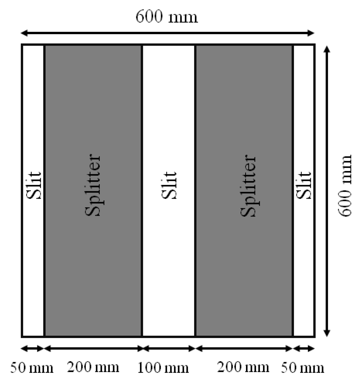
A numerical model is implemented to simulate the pressure loss in a system composed of two dissipative splitter silencers, with a length of 0.9 m, embedded in a duct (see Figure 1). The average pressure at the inlet and outlet of the system is analyzed by using the finite element method (FEM).
The stationary turbulent flow k- ε model is used for the numerical calculations. This is a two-equation turbulence model that provides the computation of the turbulent kinetic energy, k, defined as the kinetic energy associated with eddies in turbulent flow and the dissipation rate, ε , which is a parameter that is commonly used in the characterization of turbulent flow to determine the amount of energy that is lost due to viscous effects [23]. The turbulent kinetic energy and its dissipation rate are calculated from transport equations solved simultaneously with those governing the mean flow behavior [24]. This model has also the advantages of being computationally efficient and widely validated [25].
Two different profile shapes are simulated in order to study the influence of the profile shape of the silencer in the behavior of the flow and, consequently, in the pressure drop. In this work, the semihexadecagonal shape is used as an approximation of the semicircular shape described in the ISO standard.
It is also important to note that, due to the geometrical symmetry of the system, and with the purpose of saving computational power and cost, symmetric boundary conditions are considered to simulate only one quarter of the system.
Figure 2 shows the geometries of the implemented models, both with rectangular and semihexadecagonal profiles. The considered lengths of the duct downstream and upstream are chosen according to the ISO 14163, in which it is specified that the minimum distances from the silencers for measuring the pressure downstream and upstream are, respectively, 0.5 d and 6 d (d being the thickness of the splitter).
The velocity at which the flow approaches the silencers has also a significant influence on the pressure loss, as high velocities may cause turbulence that increases the drop in the pressure associated with the presence of the splitters and their influence in the behavior of the flow inside the duct. This effect is also studied by considering four different input face velocities, U 0 , in the models: 5 m/s, 10 m/s, 15 m/s and 20 m/s.
The splitter silencers used in the experimental stage of the work (see Section 4) are made of stainless steel, so the contours of these structures are considered rigid walls for the flow in the numerical simulations.
The resulting models consist of 172,953 elements in the case of rectangular profiles and 68,407 in the case of semihexadecagonal profiles. The significant difference between the number of elements generated in both meshes, even though they are set by following the same criteria, is associated with the resolution of the mesh required in the vicinity of the profiles to solve the proposed problem. On the one hand, a rectangular profile implies a drastic change in the cross section of the duct, as it is a straight wall that is perpendicular to the propagation of the flow. On the other hand, a semihexadecagonal profile leads to a gradual change that creates a smooth transition from the section of the empty duct to the section in which the silencer is present.

4. Experimental Setup

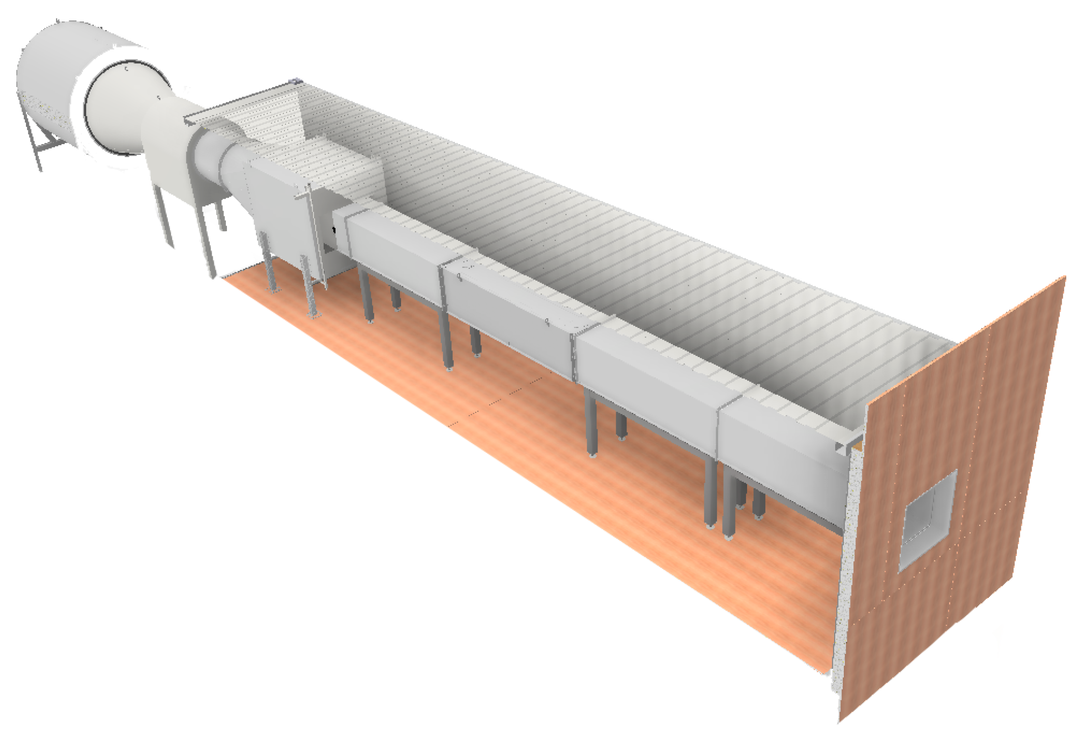
The same configurations described for the numerical models in Section 3 are experimentally measured. The test bench in which the measurements are carried out consists of a square duct with a length of 8 m and a cross section of 0.36 m 2 ( 0.6 m × 0.6 m), which is open in one ending and has an axial fan attached to the other ending (see Figure 3).
The major loss factor, h f , can be calculated by using the Darcy friction loss equation as follows:
h f = f D L D U 0 2 2 g
where f D is the Darcy friction factor, L is the length of the duct, D is the diameter of the duct, U 0 is the input face velocity (previously defined), and g is the acceleration due to gravity.
The Darcy friction factor is calculated by using the Colebrook–White equation as follows:
1 f D = 2 log ε 3.7 D h + 2.51 R e f D
where ε is the duct’s effective roughness (in this case, ε = 0.045 ), and D h is the hydraulic diameter of the duct.
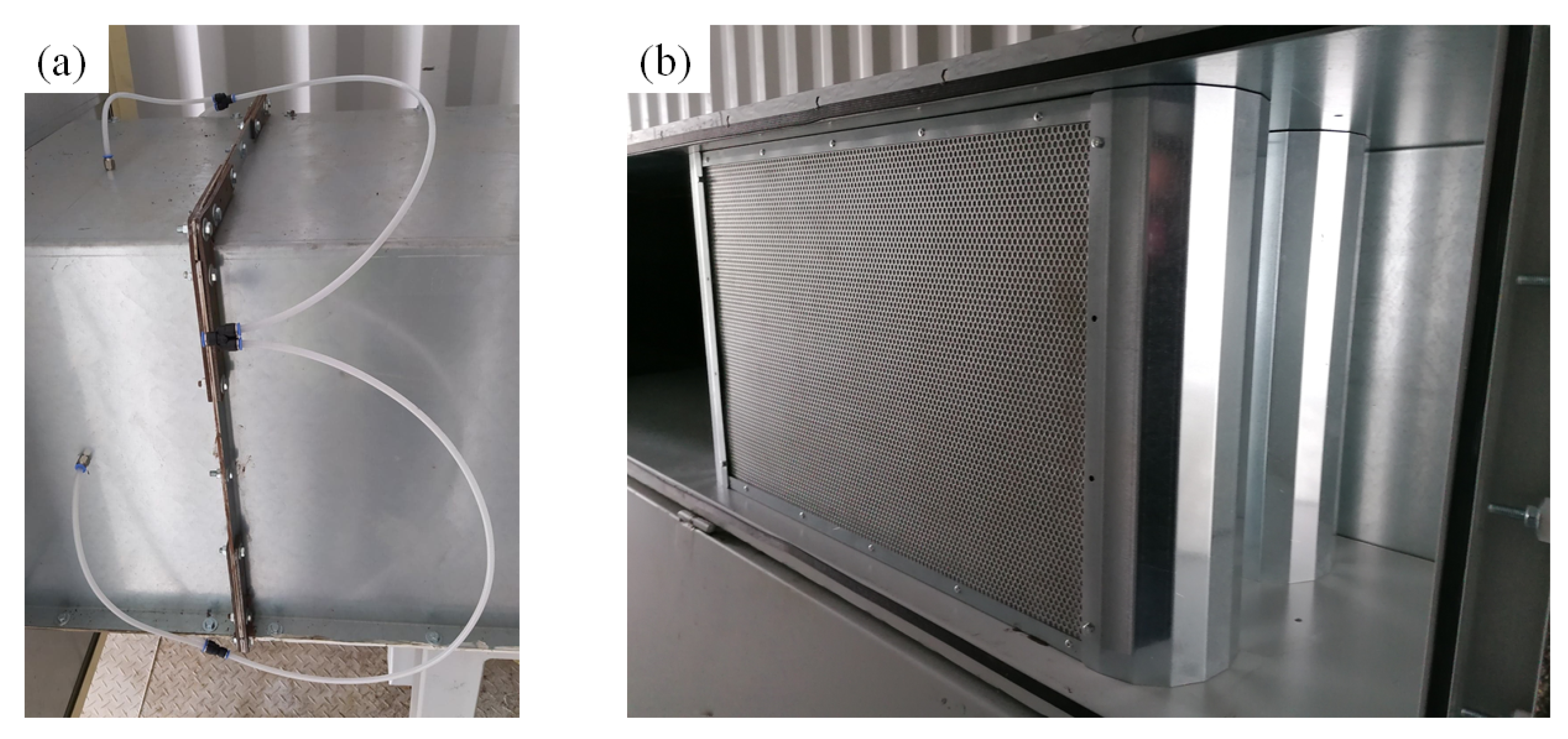
When started, the fan sucks the air entering the duct through the open-ended termination, causing a pressure difference between the downstream and upstream sections in the presence of the splitters. The pressure is measured at the center of each wall of the duct by placing eight probes, four downstream and four upstream, at the distances specified in the ISO standard ( 0.5 d downstream and 6 d upstream), as it is shown in Figure 4a. The pressures measured in the four probes placed downstream are averaged, as well as those measured upstream, in order to obtain the average total pressure at both sides of the silencer. The position of the splitter silencers in the duct is shown in Figure 4b.
In order to properly set the input face velocities to be tested, a Pitot tube is placed in the center of the cross section of the duct at a distance of 30 cm from the open-ended termination. The rotation speed of the fan is set in order to obtain the desired flow speed at the measurement point.

5. Results and Discussion

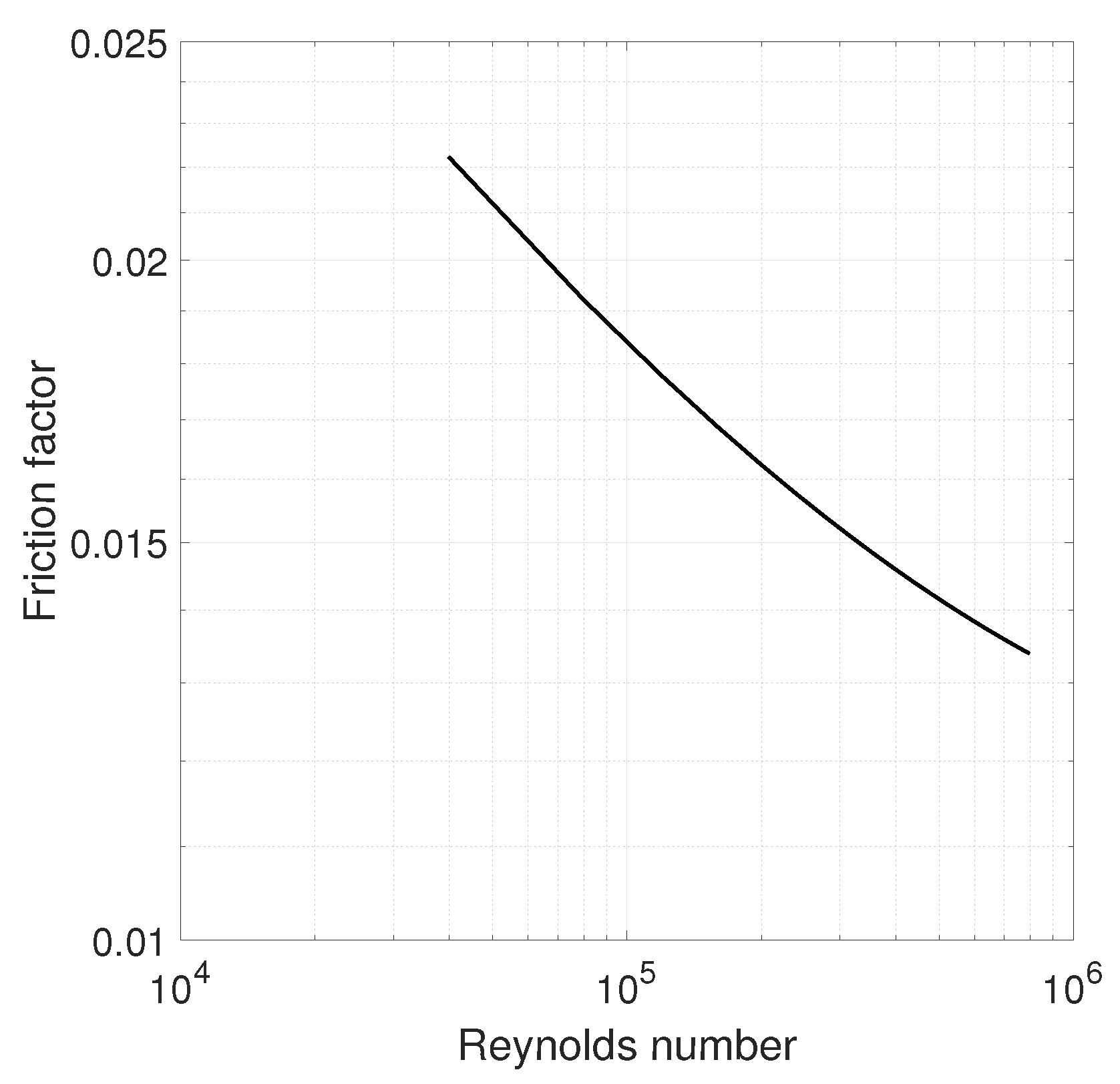
Table 2 provides the information about the Reynolds number, Darcy friction factor and major friction loss in the duct as a function of different input face velocities. With this information, it is possible to show the Moody diagram, plotted in Figure 5.
The results obtained by using the four methods described above (ISO, VDI, FEM and experimental measurements) are shown in Table 3 and Table 4, in which it is possible to see at a glance the differences in the values of the pressure loss induced by the two types of profiles. When low input face velocities are considered (around 5 m/s), there are no significant differences in the pressure loss experimentally obtained with both shapes. This is due to the fact that, even though the flow is propagating in a turbulent regime ( R e > 2100 ), its interaction with the silencers has a similar effect in the turbulence in the medium, independently of the shape of the profile. The predicted value obtained by using the four methods is also relatively similar in the four methods.
Nevertheless, for input face velocities equal to or greater than 10 m/s, the pressure loss obtained by using rectangular profiles is approximately 1.5 times that obtained with semihexadecagonal profiles. This indicates, as it was mentioned in Section 3, that the fact of inserting a rigid wall (rectangular profile) in the duct perpendicular to the direction of the propagation of the flow leads to an increase in the turbulence and loss in kinetic energy of the flow.
It is important to note that the VDI standard, unlike the ISO standard, does not include references to the shape of the silencer profile. Therefore, the same pressure loss values are predicted for both rectangular and semihexadecagonal profiles (third column in Table 3 and Table 4, respectively) when this standard is used.
Table 3 and Table 4 also show that, even if all the methods follow the same overall tendency in the prediction of the pressure loss, the differences between them increase with the considered input face velocity. This is because the behavior of the system becomes more complex as the flow velocity increases, due to the presence of turbulence and other associated phenomena that are difficult to predict.
The increase in the turbulence in the system is associated, among other factors, both to the profile shape and to the input face velocity. Figure 6 shows the numerical result of the variation of the flow velocity in the duct as a function of the position and the input face velocity. The flow velocity highly increases in the slit between both silencers, as the cross section in this region is reduced to 1 / 3 of the original cross section of the duct. This leads to a near tripling of the flow velocity in this section.
It is also remarkable the fact that the flow velocity in the case of semihexadecagonal profiles progressively increases until in reaches its maximum and, from that point on, it stays relatively flat until the flow leaves the section of the duct occupied by the splitters. In contrast to this case, when rectangular profiles are considered, a higher peak is produced in the first interaction of the flow with the silencer, which explains the greater pressure loss in this configuration.
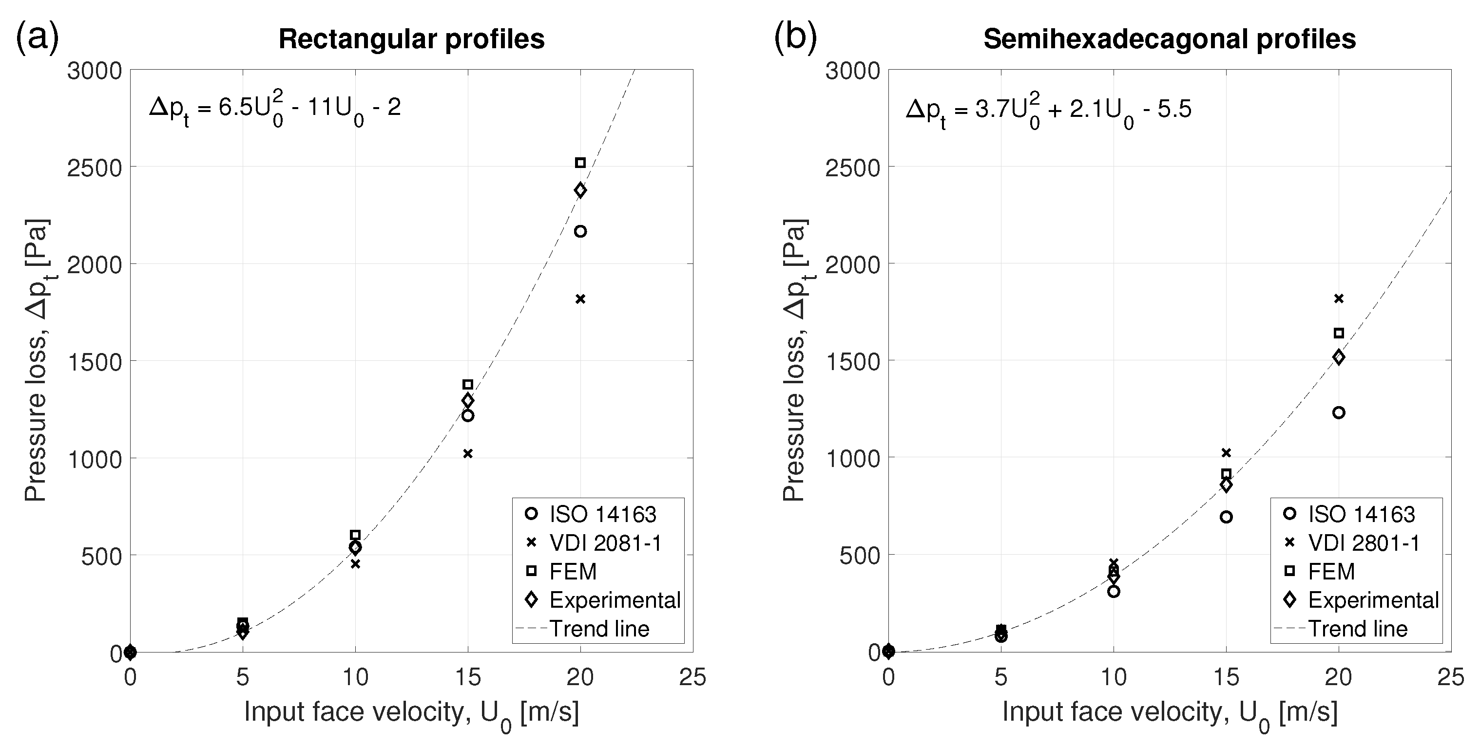
Figure 7 depicts the results presented in Table 3 and Table 4. The experimental values of the pressure loss are considered a reference for the validation of the results given by the standards and the numerical model; consequently, the trend line followed by the experimental results is also shown in this figure. The behavior of the trend lines for both types of profiles can be described by means of the second order parabolic equations that can be observed in the insets of the figure.
The coefficient of determination R 2 between the results of the pressure loss obtained by using the ISO standard and numerical methods, as a function of those obtained by means of experimental measurements, are shown in both configurations in Figure 8 and Figure 9. For the system of splitter silencers with rectangular profiles, the coefficient of determination is found to be slightly higher in numerical simulations, meaning that this model can reproduce experimental results with a slightly higher quality. On the contrary, the coefficients of determination for the system of splitter silencers with semihexadecagonal profiles are very close when the ISO standard and numerical simulations are used (a difference of 0.0001 is found).
In general, when only the R 2 coefficient is analyzed, it is possible to observe that both models can reproduce experimental results with a similar quality. Nevertheless, the difference between the results obtained with the used methods can be also studied. The difference between the predicted pressure loss obtained with ISO 14163, VDI 2081-1 and FEM with that of experimental measurements with rectangular and semihexadecagonal profiles is shown in Table 5 and Table 6. On the one hand, for the configuration in which the silencers have a rectangular profile, both ISO and FEM predict relatively similar values for the pressure loss, while the VDI clearly differs for velocities greater than 10 m/s. On the other hand, when semihexadecagonal profiles are considered, the use of numerical simulations provides results that are clearly in better agreement with the experimental results (average error of 8%) than both standards (with average errors of 20% and 18% for ISO and VDI, respectively). Consequently, it is possible to observe that the standards can accurately predict the value of the pressure loss in the cases for which they are developed, but their accuracy is reduced when slight variations of the proposed geometries are implemented.
Negative (positive) values in these tables indicate an underestimation (overestimation) of the pressure loss by a given method (ISO, VDI or FEM), compared to the experimental results. It is important to note that in many industrial sectors, the machinery is not always working in the same regime and, consequently, a buffer in these predictions is necessary. Additionally, given that some machines have technical requirements for a proper working regime, a slight overestimation of the values of the pressure loss reduces the risk in the design of the silencers to be applied. An underestimation of the pressure loss can reduce the efficiency of the machine and, consequently, affect its proper working. In this sense, the predictions resulting from the application of the FEM are more suitable for the prediction of the pressure loss in industrial applications of dissipative splitter silencers in ducts, as both standards tend to underestimate the value of the predicted pressure loss.
6. Conclusions

This work presents a comparative study on the prediction of the pressure loss in a system composed of two dissipative splitter silencers embedded in a duct by using standards (ISO 14163 and VDI 2081-1), numerical simulations (FEM) and experimental measurements. The consideration of two different profile shapes in the silencers and four different input face velocities show the importance of these factors in the resulting pressure loss, as they can strongly modify the behavior of the flow in the duct. The simulations performed by means of the FEM also show a significant improvement in the predicted results compared to both standards when semihexadecagonal profiles are considered and, at the same time, demonstrate a similar performance in the calculation of the pressure loss for rectangular profiles than the ISO standard. The results obtained by means of the FEM also show their feasibility in the prediction of the pressure loss of dissipative splitter silencers in ducts, especially in those cases that are not considered in the standards. Additionally, the FEM-implemented simulations tend to slightly overestimate this value and, consequently, the results allow a safety buffer in the design of these devices.

Author Contributions

Conceptualization, B.C.; methodology, B.C. and I.H.-D.; software, I.H.-D.; validation, B.C. and I.H.-D.; formal analysis, B.C., I.H.-D. and P.N.; investigation, B.C., I.H.-D. and P.N.; resources, B.C.; data curation, B.C. and I.H.-D.; writing—original draft preparation, I.H.-D.; writing—review and editing, B.C., I.H.-D. and P.N.; visualization, I.H.-D.; supervision, B.C. and I.H.-D.; project administration, B.C.; funding acquisition, B.C. All authors have read and agreed to the published version of the manuscript.

Funding

This research was funded by Narodowe Centrum Badań i Rozwoju (NCBR) under the project POIR.01.01.01-00-0852/18 “Development of the innovative line of “Rocket” and “Rocket-Active” types of silencers, aimed at implementing a series of next-generation acoustic products”.

Institutional Review Board Statement

Not applicable.

Informed Consent Statement

Not applicable.

Data Availability Statement

Not applicable.

Conflicts of Interest

The authors declare no conflict of interest. The funders had no role in the design of the study; in the collection, analyses, or interpretation of data; in the writing of the manuscript, or in the decision to publish the results.

References

  1. Mechel, F.P. Theory of baffle-type silencers. Acta Acust. United Acust. 1990, 72, 93–111. [Google Scholar]
  2. Allam, R.; Åbom, M. Fan noise control using microperforated splitter silencers. J. Vib. Acoust. 2014, 163, 031017. [Google Scholar] [CrossRef]
  3. Blanco, J.; Earnshaw, A. Study of the noise characteristics of motorcycles. In SAE Technical Paper Series; No. 2001-01-1209; 2001; Available online: https://www.sae.org/publications/technical-papers/content/2001-01-1209/ (accessed on 1 November 2021).
  4. Åbom, M. Micro-perforates for duct noise control. In Proceedings of the Baltic-Nordic Acoustics Meeting, Harpa, Reykjavik, Iceland, 15–18 April 2018. [Google Scholar]
  5. Baek, S.; Lee, K.; Kang, K.; Lee, I. An experimental study on acoustic performance of splitter silencers in large maritime gas turbine engines. Trans. Korean Soc. Noise Vib. Eng. 2015, 27, 503–509. [Google Scholar] [CrossRef] [Green Version]
  6. Leskov, E.A.; Osipov, G.L.; Yudin, E.J. Experimental investigation of splitter duct silencers. Appl. Acoust. 1970, 3, 47–56. [Google Scholar] [CrossRef]
  7. Cummings, A. Sound attenuation in ducts lined on two opposite walls with porous material, with some applications to splitters. J. Sound Vib. 1976, 49, 9–35. [Google Scholar] [CrossRef]
  8. Brandstät, P.; Frommhold, W.; Fisher, M.J. Program for the computation of absorptive silencers in straight ducts. Appl. Acoust. 1994, 43, 19–38. [Google Scholar] [CrossRef]
  9. Venegas, R.; Arenas, J.P.; Boutin, C. Analytical modeling of dissipative silencers. J. Acoust. Soc. Am. 2018, 144, 2998. [Google Scholar] [CrossRef] [PubMed]
  10. Murao, T.; Nishimura, M.; Gan, W.-S. A hybrid approach to active and passive noise control for open windows. Appl. Acoust. 2019, 155, 338–345. [Google Scholar] [CrossRef]
  11. Taratorin, A.; Mukhametov, A. Optimization of complexly shaped dissipative silencers. J. Akust. 2021, 39, 39. [Google Scholar]
  12. Kirby, R. A comparison between anaytic and numerical methods for modelling automotive dissipative silencers with mean flow. J. Sound Vib. 2009, 325, 565–582. [Google Scholar] [CrossRef]
  13. Zhang, H.; Fan, W.; Guo, L.-X. A CFD results-based approach to investigating acoustic attenuation performance and pressure loss of car perforated tube silencers. Appl. Sci. 2018, 8, 545. [Google Scholar] [CrossRef] [Green Version]
  14. Panigrahi, S.; Munjal, M.L. Backpressure considerations in designing of cross flow perforated-element reactive silencers. Noise Control. Eng. J. 2007, 55, 504–515. [Google Scholar] [CrossRef]
  15. Liu, C.; Ji, Z.L.; Fang, Z. Numerical analysis of acoustic attenuation and flow resistance characteristics of double expansion chamber silencers. Noise Control. Eng. J. 2013, 61, 487–499. [Google Scholar] [CrossRef]
  16. Liu, C.; Ji, Z. Computational fluid dynamics-based numerical analysis of acoustic attenuation and flow resistance characteristics of perforated tube silencers. J. Vib. Acoust. 2014, 136, 021006-1. [Google Scholar] [CrossRef]
  17. Cummings, A.; Astley, R.J. Finite element computation of attenuation in bar-silencers and comparison with measured data. J. Sound Vib. 1996, 196, 351–369. [Google Scholar] [CrossRef]
  18. Kirby, R.; Williams, P.T. A three dimensional investigation into the acoustic performance of dissipative splitter silencers. J. Acoust. Soc. Am. 2014, 135, 2727. [Google Scholar] [CrossRef] [PubMed] [Green Version]
  19. Kirby, R.; Lawrie, J.B. A point collocation approach to modelling large dissipative silencers. J. Sound Vib. 2005, 286, 313–339. [Google Scholar] [CrossRef] [Green Version]
  20. Yang, L.; Want, P.; Wu, T.W. Boundary element analysis of bar silencers using the scattering matrix with two-dimensional finite element modes. Eng. Anal. Bound. Elem. 2017, 74, 100–106. [Google Scholar] [CrossRef]
  21. ISO. ISO 14163:2017. Acoustics—Guidelines for Noise Control by Silencers; International Organization for Standardization: Genève, Switzerland, 2017. [Google Scholar]
  22. Verein Deutsche Ingenieure. VDI 2081-1:2001. Noise Generation and Noise Reduction in Air-Conditioning Systems; Verein Deutsche Ingenieure: Berlin, Germany, 2001. [Google Scholar]
  23. Wilcox, D.C. Turbulence Modeling for CFD, 3rd ed.; DCW Industries: La Canada Flintridge, CA, USA, 2008. [Google Scholar]
  24. Launder, B.E.; Spalding, D.B. The numerical computation of turbulent flows. Comput. Methods Appl. Mech. Eng. 1974, 3, 269–289. [Google Scholar] [CrossRef]
  25. Versteeg, H.K.; Malalasekera, W. An introduction to Computational Fluid Dynamics, 2nd ed.; Pearson Education Limited: Harlow, UK, 1995. [Google Scholar]
Figure 1. A 2D scheme of the studied system, composed of two dissipative splitter silencers embedded in a duct.
Applsci 11 10998 g001
Figure 2. Geometry of the implemented numerical model with (a) rectangular profiles and (b) semihexadecagonal profiles in the silencer.
Applsci 11 10998 g002
Figure 3. A 3D model of the test bench setup used for the experimental measurements of pressure loss.
Applsci 11 10998 g003
Figure 4. (a) Sampling probes for the pressure in the walls of the duct, (b) position of the splitter silencers in the duct.
Applsci 11 10998 g004
Figure 5. Moody diagram of the duct used for experimental measurements.
Applsci 11 10998 g005
Figure 6. Numerical result of the variation of the flow velocity along the duct as a function of the position and the input face velocity in splitter silencers with (a) rectangular and (b) semihexadecagonal profiles.
Applsci 11 10998 g006
Figure 7. Pressure loss in splitter silencers with (a) rectangular and (b) semihexadecagonal profiles as a function of the input face velocity, U 0 . The dashed black lines show the trend lines followed by the experimental results, used to obtain the fitting equation.
Applsci 11 10998 g007
Figure 8. Coefficient of determination R 2 between (a) analytical (ISO) and experimental results and (b) numerical and experimental results for the configuration of splitter silencers with rectangular profiles.
Applsci 11 10998 g008
Figure 9. Coefficient of determination R 2 between (a) analytical (ISO) and experimental results and (b) numerical and experimental results for the configuration of splitter silencers with semihexadecagonal profiles.
Applsci 11 10998 g009
Table 1. Values of the coefficients for the calculation of the pressure loss coefficient (Equation (5)) in VDI 2081-1.
Thickness of Splitter a 1 a 2 b 1 b 2
100 mm0.2350.017−2.78−2.70
200 mm0.2550.015−2.82−2.91
300 mm0.2940.0167−2.83−2.95
Table 2. Reynolds number, Darcy friction factor and major friction loss as a function of the input face velocity.
U 0 [m/s] Re f D h f [m]
139,8410.02220.02
279,6810.01920.06
3119,5220.01780.14
4159,3630.01690.24
5199,2030.01620.38
6239,0440.01580.54
7278,8840.01540.74
8318,7250.01510.97
9358,5660.01481.22
10398,4060.01461.51
11438,2470.01441.83
12478,0880.01422.18
13517,9280.01412.55
14557,7690.01402.96
15597,6100.01383.40
16637,4500.01373.87
17677,2910.01364.37
18717,1310.01364.90
19756,9720.01355.46
20796,8130.01346.05
Table 3. Pressure loss (in Pascals) obtained with ISO 14163, VDI 2081-1, FEM and experimental measurements for the system of splitters with rectangular profiles.
U 0 [m/s]ISO 14163VDI 2081-1FEMExperimental
5135114153106
10542455604538
151218102313781295
202166181825192378
Table 4. Pressure loss (in Pascals) obtained with ISO 14163, VDI 2081-1, FEM and experimental measurements for the system of splitters with semihexadecagonal profiles.
U 0 [m/s]ISO 14163VDI 2081-1FEMExperimental
57711411098
10308455411386
156921023914859
201230181816401517
Table 5. Difference between the predicted pressure loss (in Pascals) obtained with ISO 14163, VDI 2081-1 and FEM with that of experimental measurements for the system of splitters with rectangular profiles.
U 0 [m/s]ISO 14163VDI 2081-1FEM
529847
104−8366
15−77−27283
20−212−560141
Table 6. Difference between the predicted pressure loss (in Pascals) obtained with ISO 14163, VDI 2081-1 and FEM with that of experimental measurements for the system of splitters with semihexadecagonal profiles.
U 0 [m/s]ISO 14163VDI 2081-1FEM
5−21−1612
10−78−6925
15−167−16455
20−287−301123
Publisher’s Note: MDPI stays neutral with regard to jurisdictional claims in published maps and institutional affiliations.