
Tailored Lace: Moldless Fabrication of 3D Bio-Composite Structures through an Integrative Design and Fabrication Process


Abstract
:1. Introduction
1.1. Fibre-Reinforced Polymers
1.2. Natural Fibre-Reinforced Polymers
1.3. Production Methods
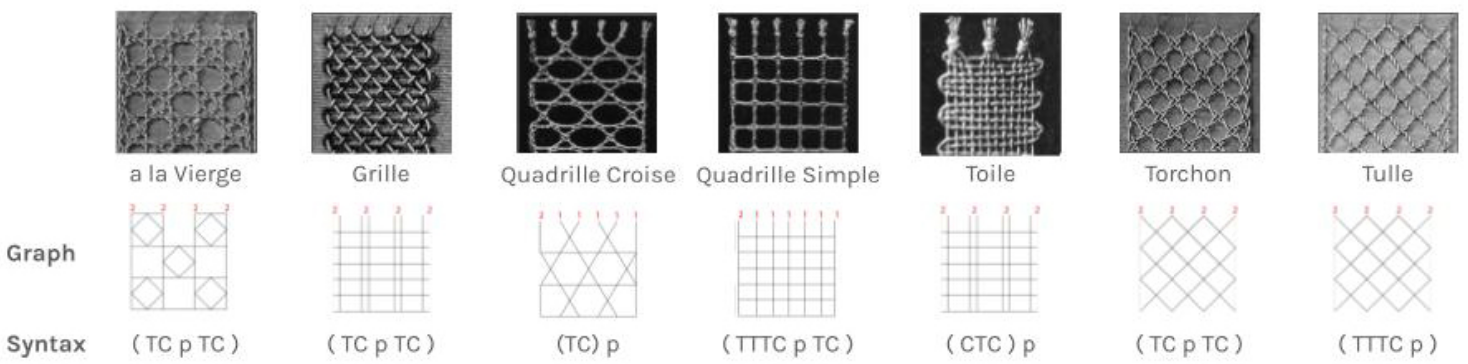
1.4. Bobbin Lace Making
“like endangered plants and animals, not only is the loss of handcraft a reduction in the beauty and diversity of the world, but it is also the loss of solutions to medical, social and environmental problems”[13].
1.5. State of the Art
1.6. Scope
2. Materials and Methods
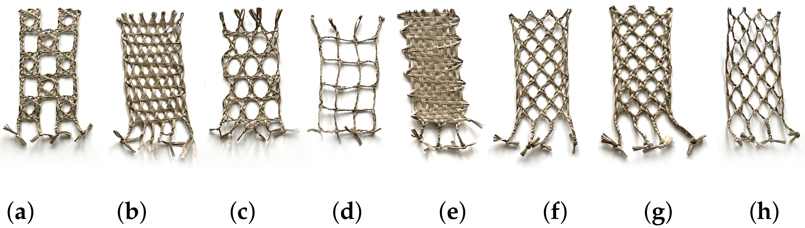
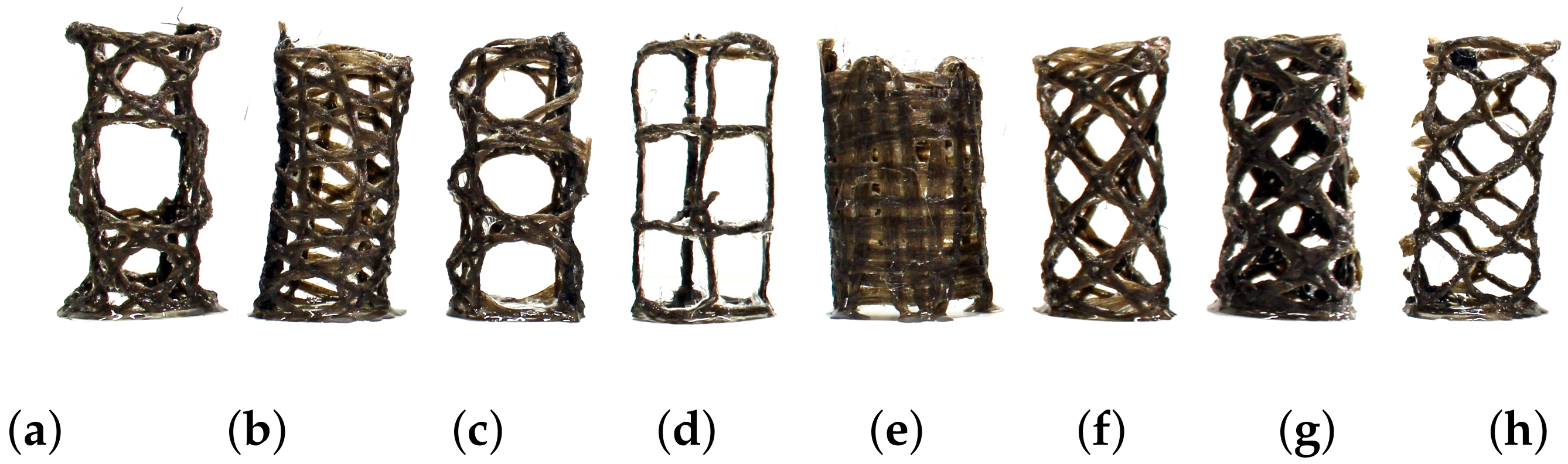
2.1. Bobbin Lace Analysis
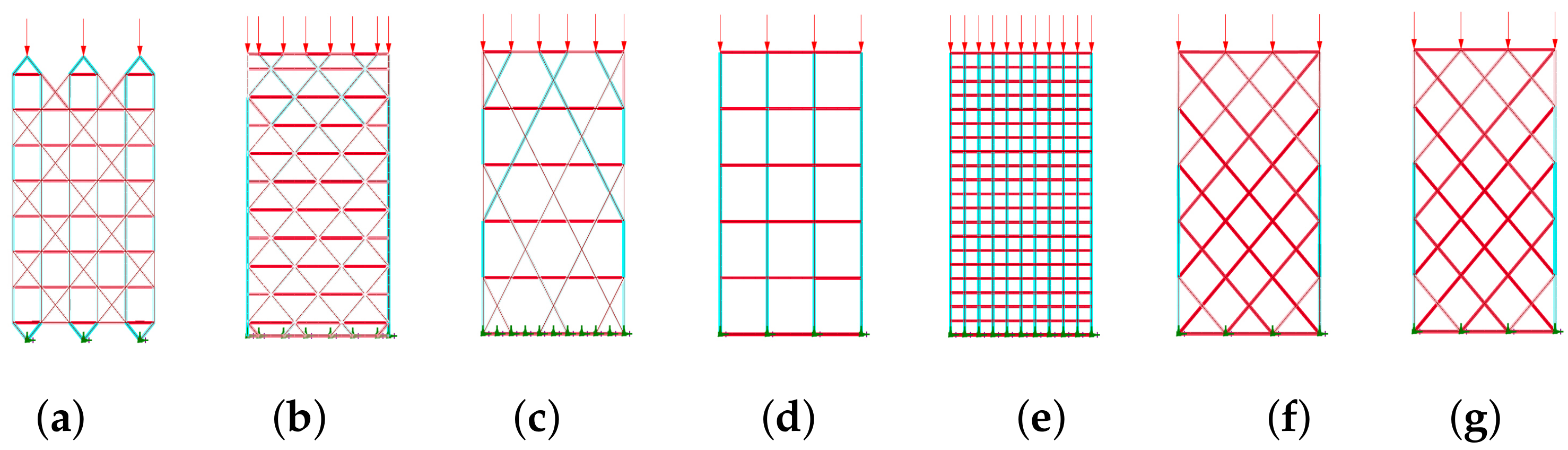
2.2. Structural Analysis
2.2.1. Physical Tests
2.2.2. Digital Analysis
2.3. Computational Design
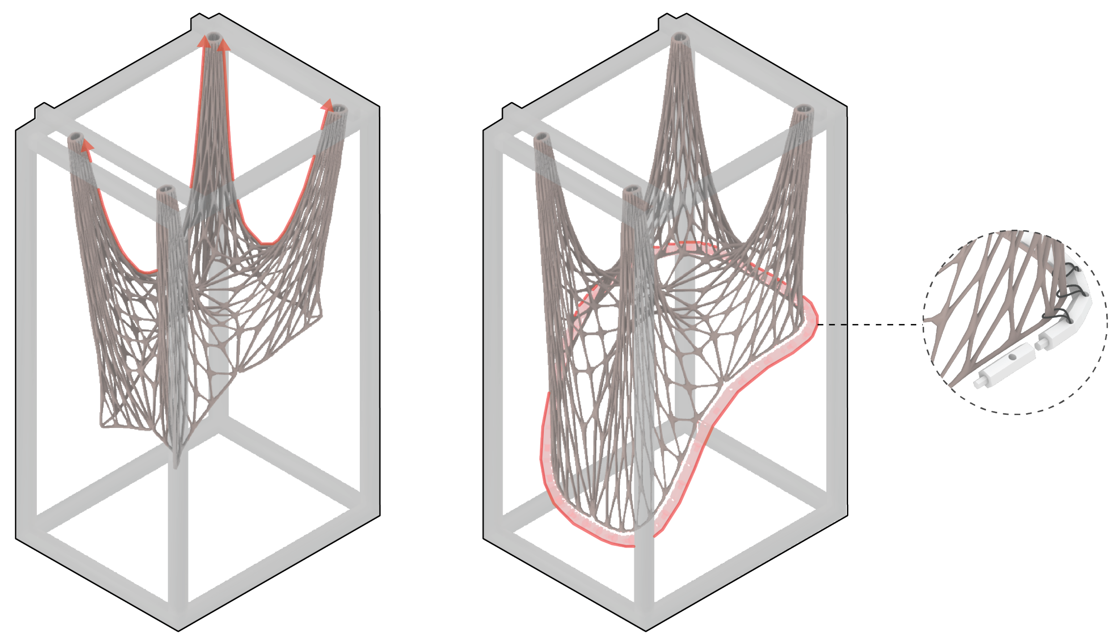
2.3.1. Form Finding
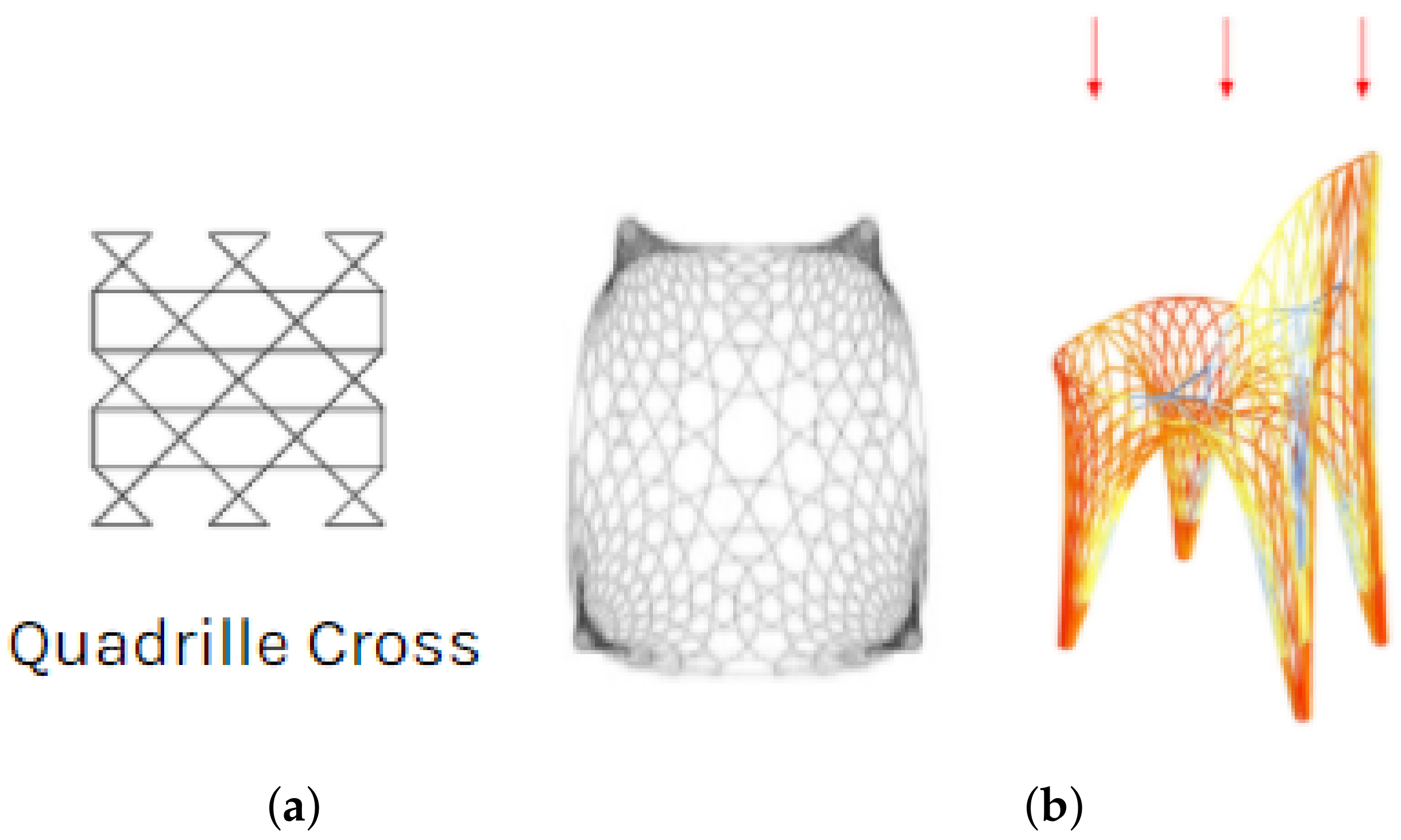
2.3.2. Applied Patterning
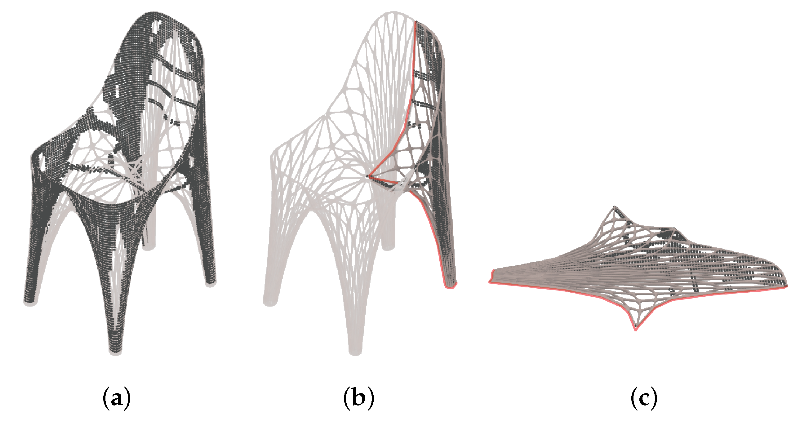
2.3.3. Topology Optimisation
2.3.4. Fabrication Preparation
2.4. Fabrication Methods
2.4.1. Templates
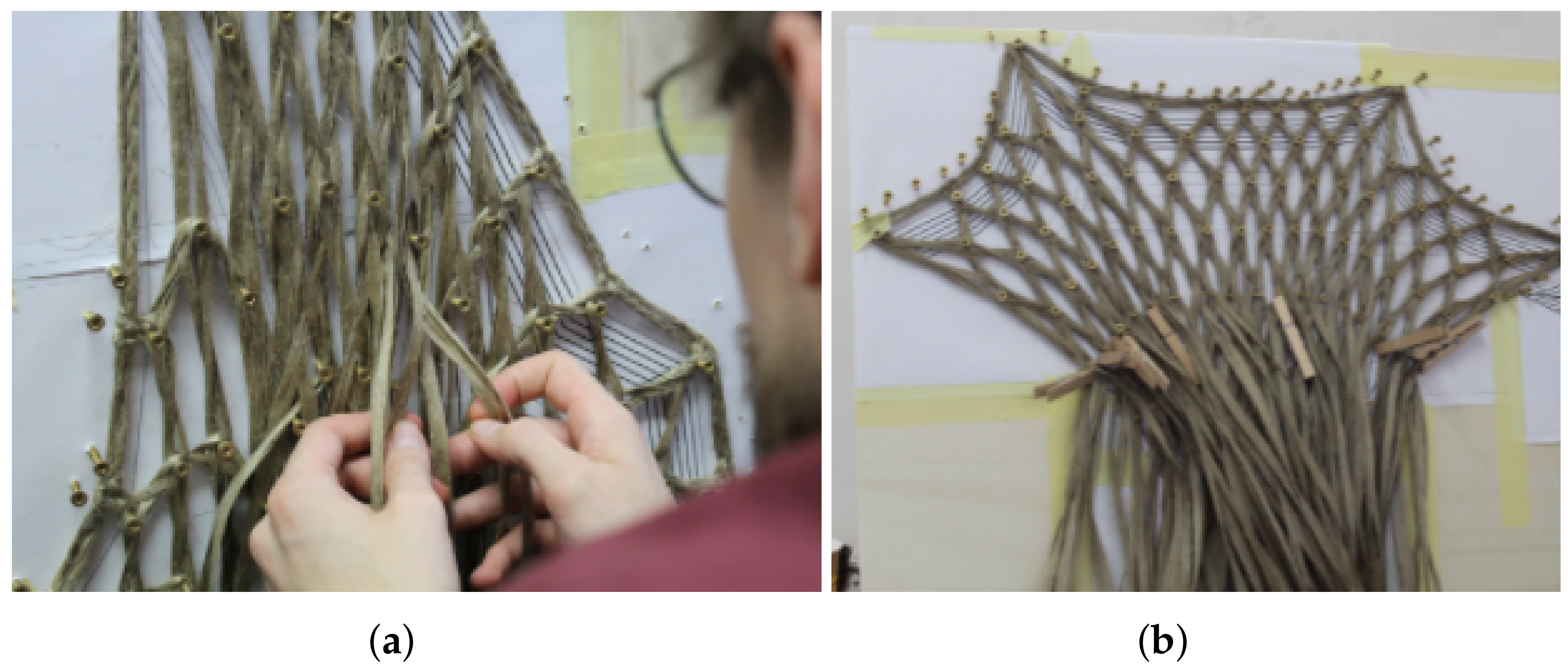
2.4.2. Lacing
2.4.3. Stitching
2.4.4. Resin Infusion
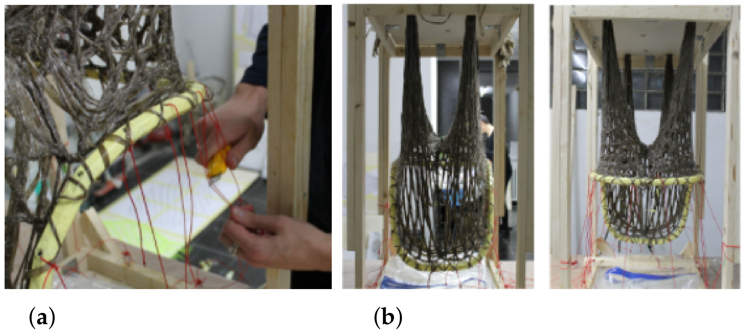
2.4.5. Forming
2.4.6. Assembly
3. Results
3.1. Integrated Workflow
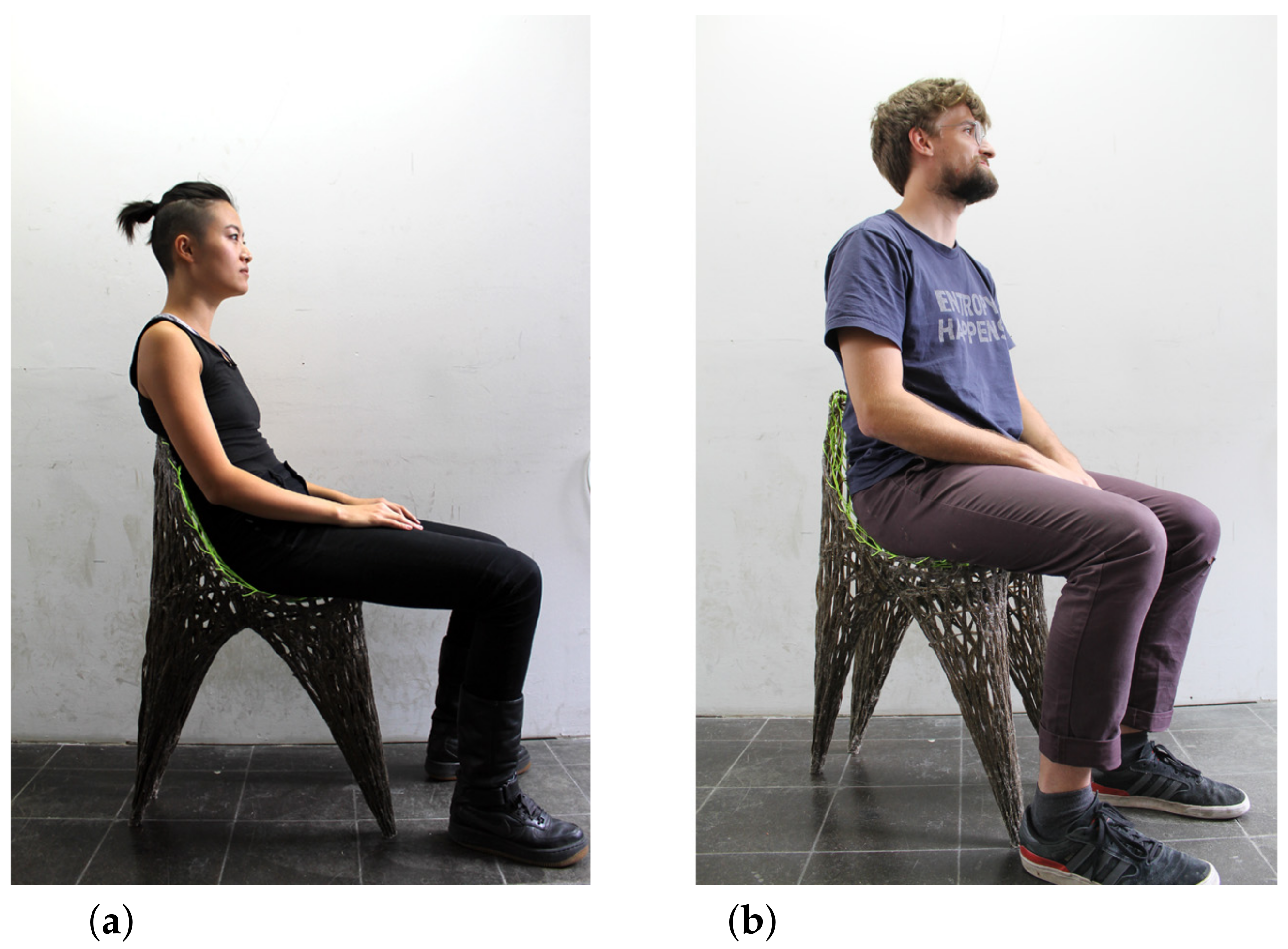
3.2. Demonstrator
3.3. Performance
4. Outlook
- i
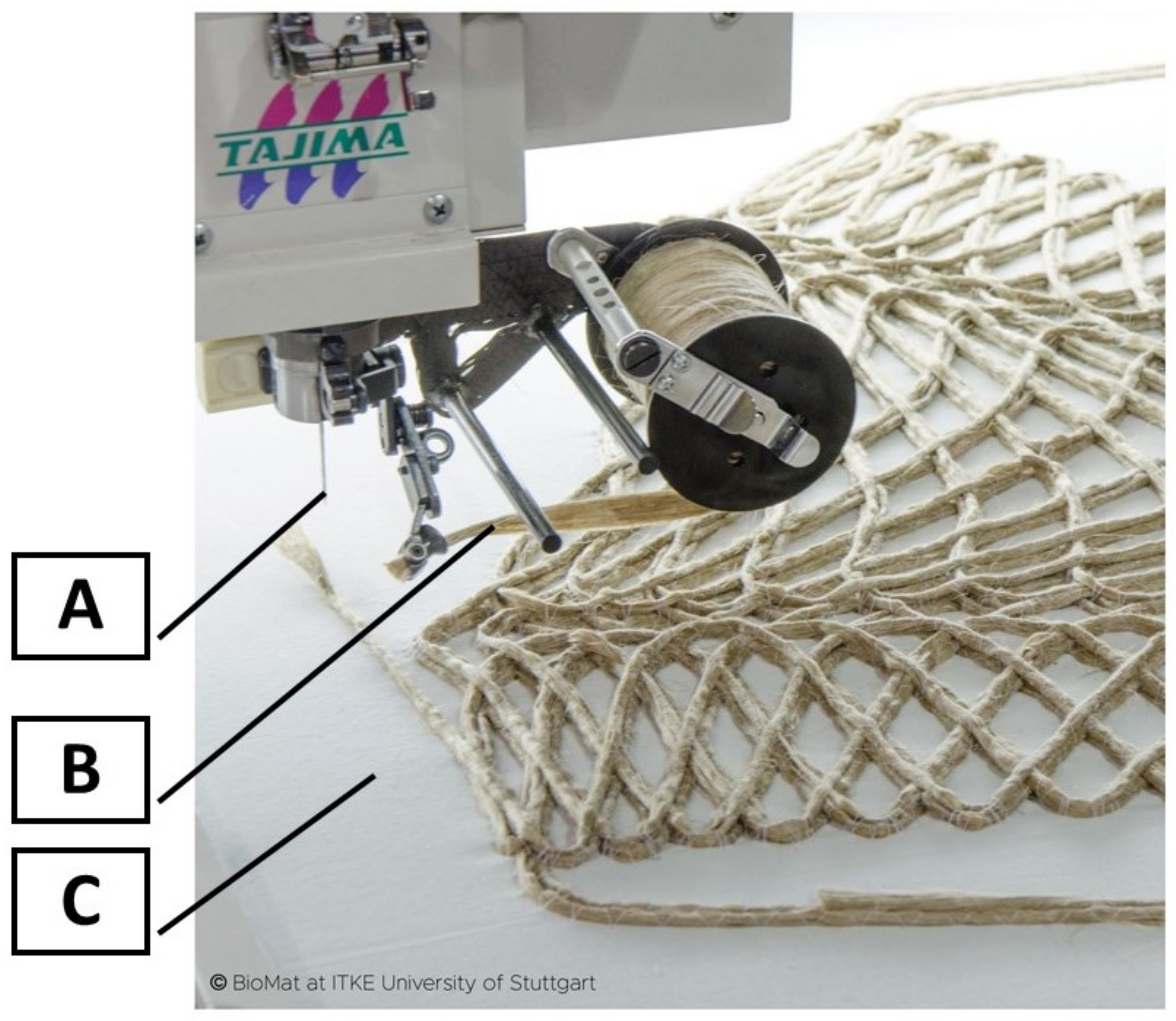
- Maximum preform size: The maximum size of a single preform produced is limited by the size of the machine working area. In case of the Tajima TFP machine, which was used in the experiment, it required discretization of the chair design into preforms of max. 70 × 70 cm. The individual pieces were later stitched together and hung on the frame.
- ii
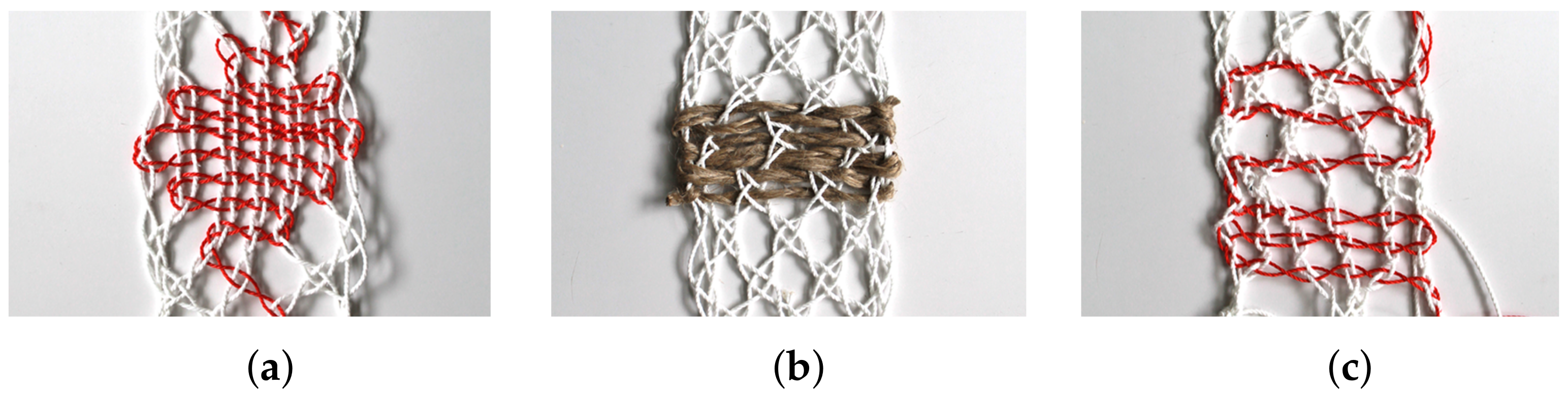
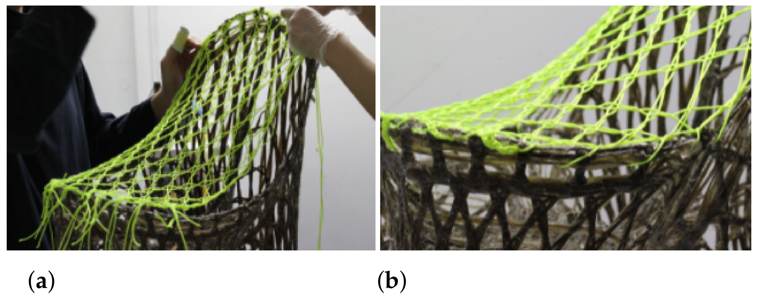
- Fibre interactions: TFP specimens lack the unique fibre–fibre interactions in bobbin lace. Manually laced pieces allow fibre movement at each node, giving the global pattern freedom to deform when it is stretched. In the hanging process, this means the nodes can slip and hinge to “find” a suitable form. However, in TFP, fibres are layered on top of each other and fixed with cotton threads, constraining the angle between conjoining fibres. This change in the mechanism of fibre interaction adversely affects forming by constraining movement at the lace nodes. Fibres are prevented from self-adjusting, resulting in a less natural global form. A more deformable, knitted membrane material could be used to compensate for this effect, which might allow the geometry to find its natural equilibrium shape when hung. This can be verified in the future through physical testing.
5. Discussion
Supplementary Materials
Author Contributions
Funding
Institutional Review Board Statement
Informed Consent Statement
Data Availability Statement
Acknowledgments
Conflicts of Interest
References
- Alberto, M. Introduction of Fibre-Reinforced Polymers—Polymers and Composites: Concepts, Properties and Processes. In Fiber Reinforced Polymers—The Technology Applied for Concrete Repair; Masuelli, M., Ed.; InTech: London, UK, 2013. [Google Scholar] [CrossRef] [Green Version]
- Rajak, D.; Pagar, D.; Menezes, P.; Linul, E. Fiber-Reinforced Polymer Composites: Manufacturing, Properties, and Applications. Polymers 2019, 11, 1667. [Google Scholar] [CrossRef] [PubMed] [Green Version]
- Humphreys, M. The Use of Polymer Composites in Construction; Queensland University of Technology: Brisbane, Australia, 2003; pp. 1–9. [Google Scholar]
- Cherif, C. (Ed.) Textile Materials for Lightweight Constructions; Springer: Berlin/Heidelberg, Germany, 2016. [Google Scholar] [CrossRef]
- United Nations Environment Programme; Global Alliance for Buildings and Construction. 2020 Global Status Report for Buildings and Construction: Towards a Zero-emissions, Efficient and Resilient Buildings and Construction Sector—Executive Summary; UN Environment Programme (UNEP): Nairobi, Kenya, 2020. [Google Scholar]
- Dahy, H. Natural Fibre-Reinforced Polymer Composites (NFRP) Fabricated from Lignocellulosic Fibres for Future Sustainable Architectural Applications, Case Studies: Segmented-Shell Construction, Acoustic Panels, and Furniture. Sensors 2019, 19, 738. [Google Scholar] [CrossRef] [PubMed] [Green Version]
- Universität Freiburg. Robotically Wound Natural Fibre Construction. 2021. Available online: https://www.pr.uni-freiburg.de/pm-en/press-releases-2021/robotically-wound-natural-fibre-construction (accessed on 10 October 2021).
- Rihaczek, G.; Klammer, M.; Başnak, O.; Petrš, J.; Grisin, B.; Dahy, H.; Carosella, S.; Middendorf, P. Curved Foldable Tailored Fiber Reinforcements for Moldless Customized Bio-Composite Structures. Proof of Concept: Biomimetic NFRP Stools. Polymers 2020, 12, 2000. [Google Scholar] [CrossRef] [PubMed]
- Reichert, S.; Schwinn, T.; La Magna, R.; Waimer, F.; Knippers, J.; Menges, A. Fibrous structures: An integrative approach to design computation, simulation and fabrication for lightweight, glass and carbon fibre composite structures in architecture based on biomimetic design principles. Comput.-Aided Des. 2014, 52, 27–39. [Google Scholar] [CrossRef]
- Prado, M.; Dörstelmann, M.; Schwinn, T.; Menges, A.; Knippers, J. Core-Less Filament Winding. In Robotic Fabrication in Architecture, Art and Design 2014; McGee, W., de Leon, M., Eds.; Springer: Berlin/Heidelberg, Germany, 2014; pp. 275–289. [Google Scholar] [CrossRef]
- Dahy, H. Biocomposite materials based on annual natural fibres and biopolymers—Design, fabrication and customized applications in architecture. Constr. Build. Mater. 2017, 147, 212–220. [Google Scholar] [CrossRef]
- Fuhrmann, B. Bobbin Lace: An Illustrated Guide to Traditional and Contemporary Techniques; Dover Books on Needlepoint, Embroidery: Dover, UK, 1985. [Google Scholar]
- Irvine, V. Lace Tessellations: A Mathematical Model for Bobbin Lace and An Exhaustive Combinatorial Search for Patterns. Ph.D. Thesis, University of Victoria, Victoria, BC, Canada, 2016. [Google Scholar]
- Noel, V.A.A. Situated Computations: Bridging Craft and Computation in the Trinidad and Tobago Carnival. Dearq 2020, 27, 62–75. [Google Scholar] [CrossRef]
- Estrada, R.D.; Wyller, M.; Dahy, H. Aerochair Integrative design methodologies for lightweight carbon fiber furniture design. In Blucher Design Proceedings; Editora Blucher: Sao Paulo, Brazil, 2019; pp. 691–702. [Google Scholar] [CrossRef]
- Costalonga Martins, V.; Cutajar, S.; van der Hoven, C.; Baszyński, P.; Dahy, H. FlexFlax Costalonga Martins, V.; Cutajar, S.; van der Hoven, C.; Baszyński, P.; Dahy, H. FlexFlax Stool: Validation of Moldless Fabrication of Complex Spatial Forms of Natural Fiber-Reinforced Polymer (NFRP) Structures through an Integrative Approach of Tailored Fiber Placement and Coreless Filament Winding Techniques. Appl. Sci. 2020, 10, 3278. [Google Scholar] [CrossRef]
- Elberfeld, N.; Waller, A.; Tessmer, L. A Case for Lace: Braided Textiles for Architectural Fabrication. In Distributed Proximities, Proceedings of the 40th Annual Conference of the Association of Computer Aided Design in Architecture (ACADIA), Online, 24–30 October 2020; ACADIA Publishing Company: Lafayette, LA, USA, 2020. [Google Scholar]
- Irvine, V.; Ruskey, F. Developing a mathematical model for bobbin lace. J. Math. Arts 2014, 8, 95–110. [Google Scholar] [CrossRef] [Green Version]
- De Dillmont, T. Les Dentelles aux Fuseaux, 1st ed.; Bibliothèque DMC: Mulhouse, France, 1921. [Google Scholar]
- Preisinger, C. Linking Structure and Parametric Geometry. Archit. Des. 2013, 83, 110–113. [Google Scholar] [CrossRef]
- Piker, D. Kangaroo: Form Finding with Computational Physics. Archit. Des. 2013, 83, 136–137. [Google Scholar] [CrossRef]
- Bialkowsk, S. tOpos: GPGPU Accelerated Structural Optimisation Utility for Architects. In Proceedings of the 35th International Conference on Education and Research in Computer Aided Architectural Design in Europe, Rome, Italy, 20–22 September 2017; pp. 679–688. [Google Scholar]
- Dahy, H.; Petrš, J.; Baszyński, P. Design and Fabrication of two 1:1 Architectural Demonstrators based on Biocomposites from Annually Renewable Resources displaying a Future Vision for Sustainable Architecture. In Proceedings of the FABRICATE 2020, Online, 9–12 September 2020. [Google Scholar]


| Pattern | Fibre | Weight | F Max | dL at Fmax | Strength |
|---|---|---|---|---|---|
| (mm) | (g) | (N) | (mm) | (mPa) | |
| (a) A la Vierge | 340 | 20 | 360 | 10 | 0.18 |
| (b) Grille * | 320 | 20 | 568 | 8.2 | 0.28 |
| (c) Quadrille Croise | 320 | 20 | 520 | 5.1 | 0.26 |
| (d) Quadrille Simple | 240 | 13 | 251 | 6.7 | 0.13 |
| (e) Toile * | 280 | 22 | 1090 | 18.1 | 0.55 |
| (f) Torchon | 270 | 19 | 489 | 17 | 0.24 |
| (g) Torchon Double | 540 | 34 | 1230 | 8.8 | 0.62 |
| (h) Tulle | 280 | 18 | 234 | 10.6 | 0.12 |
| Pattern | Fibre Length | dL max | Normal Force max |
|---|---|---|---|
| (mm) | (mm) | (N) | |
| (a) A la Vierge | 310 | 2.2 | 1010 |
| (b) Grille * | 316 | 9.8 | 860 |
| (c) Quadrille Croise | 318 | 1.9 | 710 |
| (d) Quadrille Simple | 140 | 2.4 | 810 |
| (e) Toile * | 430 | 3.1 | 250 |
| (f) Torchon | 216 | 7.9 | 1740 |
| (g) Torchon Double | 432 | 1.9 | 1740 |
| (h) Tulle | 216 | 7.9 | 1740 |
Publisher’s Note: MDPI stays neutral with regard to jurisdictional claims in published maps and institutional affiliations. |
© 2021 by the authors. Licensee MDPI, Basel, Switzerland. This article is an open access article distributed under the terms and conditions of the Creative Commons Attribution (CC BY) license (https://creativecommons.org/licenses/by/4.0/).
Share and Cite
Lehrecke, A.; Tucker, C.; Yang, X.; Baszynski, P.; Dahy, H. Tailored Lace: Moldless Fabrication of 3D Bio-Composite Structures through an Integrative Design and Fabrication Process. Appl. Sci. 2021, 11, 10989. https://doi.org/10.3390/app112210989
Lehrecke A, Tucker C, Yang X, Baszynski P, Dahy H. Tailored Lace: Moldless Fabrication of 3D Bio-Composite Structures through an Integrative Design and Fabrication Process. Applied Sciences. 2021; 11(22):10989. https://doi.org/10.3390/app112210989
Chicago/Turabian StyleLehrecke, August, Cody Tucker, Xiliu Yang, Piotr Baszynski, and Hanaa Dahy. 2021. "Tailored Lace: Moldless Fabrication of 3D Bio-Composite Structures through an Integrative Design and Fabrication Process" Applied Sciences 11, no. 22: 10989. https://doi.org/10.3390/app112210989
APA StyleLehrecke, A., Tucker, C., Yang, X., Baszynski, P., & Dahy, H. (2021). Tailored Lace: Moldless Fabrication of 3D Bio-Composite Structures through an Integrative Design and Fabrication Process. Applied Sciences, 11(22), 10989. https://doi.org/10.3390/app112210989