Article

Design and Experimental Study of Potato-Soil Separation Device for Sticky Soils Condition

1
College of Mechanical and Electrical Engineering, Hunan Agriculture University, Changsha 410128, China
2
Hunan Key Laboratory of Intelligent Agricultural Machinery and Equipment, Changsha 410128, China
*
Author to whom correspondence should be addressed.
Appl. Sci. 2021, 11(22), 10959; https://doi.org/10.3390/app112210959
Submission received: 11 October 2021 / Revised: 13 November 2021 / Accepted: 17 November 2021 / Published: 19 November 2021
(This article belongs to the Section Agricultural Science and Technology)

Abstract

:
The potato-soil separation device comprising five function areas (i.e., shearing, bending, throwing, cleaning, and conveying) was developed to address the mentioned problems (e.g., soil with high moisture content, large viscosity, and poor separation efficacy) in the harvesting process for winter idle paddy fields of Southern China. Given the kinetic analyses for the potato-soil mixture of five function areas, the crucial factors of the effect of potato-soil separation were determined. Subsequently, the orthogonal test of 4 factors and 3 levels was performed, and the percentage of small soil λ, the percentage of soil adhering to potato tuber γ, and damage rate of potato tuber K were adopted as assessment indexes. Regression analyses and programming for the orthogonal test result were conducted to optimize the device run parameters, and the optimal run parameters included the rotational speed of the soil-crushing mechanism of 84.18 r/min, linear velocity of second-stage lifting chain of 0.75 m/s, and inclination angle of lifting chain of 15.87°. The field experiments were performed with the modified potato harvester. As indicated from the result, the visible potato rate was 94.31% and damage rate of potato was 0.89%, and the requirement of the national standard was satisfied. This study presented technical feasibility data and equipment for potato-soil separation under sticky soils condition.

1. Introduction

To cultivate potatoes in winter-fallowed paddy fields of Southern China, the arable land required does not compete with other crops, thereby elevating land use rates and creating vast economic benefits [1]. The winter potato is harvested in the rainy season per year (March–May), and the soils are significantly sticky as compared with other areas, which are attributed to high moisture content in soils [2]. The moisture content in soils significantly impacts the potato harvester performance [3,4,5], thereby directly causing the difficulty of mechanically harvesting in Southern China. At this time, the coarse-textured (sand) soils in the North China Plain are currently targeted by most of all marketed potato harvesters, instead of for the wet soil in hilly and mountainous areas of Southern China. For this reason, a potato harvester suitable for operation under wet soil conditions should be developed.
The prime targets for potato harvester working consist of soil excavation and potato-soil separation. To meet the mentioned objectives under wet soil conditions, a systemic study on the two critical devices (i.e., digging shovel and separation device) was conducted by predecessors. For digging devices, digging depth and overcoming resistance performance are determined by the shape size and structural form of the shovel. Vibratory [6,7], bionic [8,9], curved [10,11], and other digging shovels are widely studied and applied to sticky soils to achieve resistance reduction, thus reducing the power consumption of the whole machine. Digging depth is an important indicator, as the digging depth increases, the power consumption increases, the probability of potatoes not being harvested decreases. Due to the reduced soil-to-potato ratio, this makes subsequent soil separation more difficult, but also creates a buffer between the machine and the potato tubers, reducing the rate of potato damage [12,13]. For the separation device, its design plays a decisive role in the soil separation effect. Numerous research have been done on the innovative design of the separation mechanism, such as swing sieve [14,15,16], lifting chain [13,17,18,19], rotating disc [20,21], and different types of separation mechanisms are suitable for different soil conditions. Under sticky clay soil conditions, the soil adheres to the surface of the mechanism, making it difficult to separate and break. To solve the problem, a rubber roller and auger blade grate cleaning mechanisms mounted below the lifting chain were used to assist in cleaning the soil, and the results showed that the thickness of soil adhering to the chain rods with the cleaning mechanism was much lower than that of the chain rods without the cleaning mechanism, and the separation efficiency was improved [22]. At the same time, clay tends to adhere to the potato surface, so that potatoes are not easily found after harvesting. To improve visible potato rate, a cross rotating agitator was installed at the lifting chain, so that the process of separating the potato-soil mixture is improved [23]; in addition, in order to effectively break the soil, a finger wheel type rubber roller was applied to the back of the digging shovel, which accelerated the breaking of the potato-soil mixture through the rotating strike of the finger [24]. A V-type distributor was also used to directly crush the potato/soil mixture to facilitate separation, and the optimal feeding speed was defined by theoretical calculations [18]. In addition to the structural innovation of the separation mechanism, the structure and operating parameters had been evaluated and optimized by a large number of studies to improve the separation efficiency and reduce damage rate of potato. Regarding the structural parameters, the length [14,25], shape [17], inclination angle, spacing between chain rods [26,27] and arrangement of lifting chain directions [28,29] were considered to have an effect on the separation performance. There were some studies that showed that a new type of lifting chain under the condition of heavy soil had the best harvesting effect when the length of the lifting chain was 3.1 m, the linear speed of the lifting chain was 1.5 m/s, and the forward speed of the machine was 1.2 m/s [22]; a multi-stage separation buffer potato harvester achieved the visible potato rate of 99.1% by selecting a working speed of 1.05 m/s, a digging depth of 180 mm, and a screen inclination angle of 22° [27]. Other researchers found that the potato-soil mixture has different motion states on the vibration and wave segments [17]. In terms of operating parameters, numerous studies had revealed the relationship between machine forward speed [4,13,14,16,21], amplitude and vibration frequency of lifting chain [19], and separation screen operating speed [12,17] and harvester separation performance. There are mathematical models showed that forward speed of 1.1 m/s, linear speed of transverse conveyor belt of 1.5 m/s, and circular track speed of 7 r/min were the best combination performances for efficient separation [21]. Likewise, the mathematical model based on each influencing factor on the evaluation index was established, and the result showed that the amplitude of 34.1 mm, the vibration frequency of 5.24 Hz, and the operating speed of the separation screen of 2.05 m/s was conducive to potato-soil separation [19]. For potato harvesters with alternating direction, the experiment found that a reasonable combination of machine operation parameters was a forward speed of 1.3 m/s, a separation screen operating speed of 1.2 m/s, and a separating screen inclination angle of 15° [28]. The material used to make the separation device was thought to be related to the potato-soil separation performance [30], such as the use of rubber sleeves to wrap the paddle fingers on finger-wheel potato harvesters, thus reducing the potato damage rate [24]. At the same time, research methods for potato-soil separation devices are being innovated. Technical means such as high-speed camera [12,16,19,27], discrete element method (DEM) [26], and machine vision-assisted separation [3] had been used in the study of potato-soil separation.
From the available studies, the reported potato harvesters are designed for specific conditions in the local area. Combined with research and production experience, there are currently a few models for mechanized harvesting of potatoes in winter idle paddy fields in South of China, so it is necessary to develop corresponding machine models in a targeted manner, and optimize the design of structural parameters.
In this study, a new type of potato harvester, aiming at the problem of potato harvest in idle winter paddy field in South China, was developed. Potato-soil separation device (i.e., a soil-crushing mechanism and multi-stage lifting chain) based on the force analysis in the potato-soil separation and transportation and by complying with the characteristics of clay soil was designed to separate potato-soil mixture under combined shearing, bending, and collision. By the kinetic analyses for the potato-soil mixture of five function areas (i.e., shearing, bending, throwing, cleaning, and conveying), the vital factors of the separation effect are determined. Single-factor experiments and orthogonal tests considering both separation effect and potato injury were conducted, and the structure and operating parameters of the separation device were optimized.

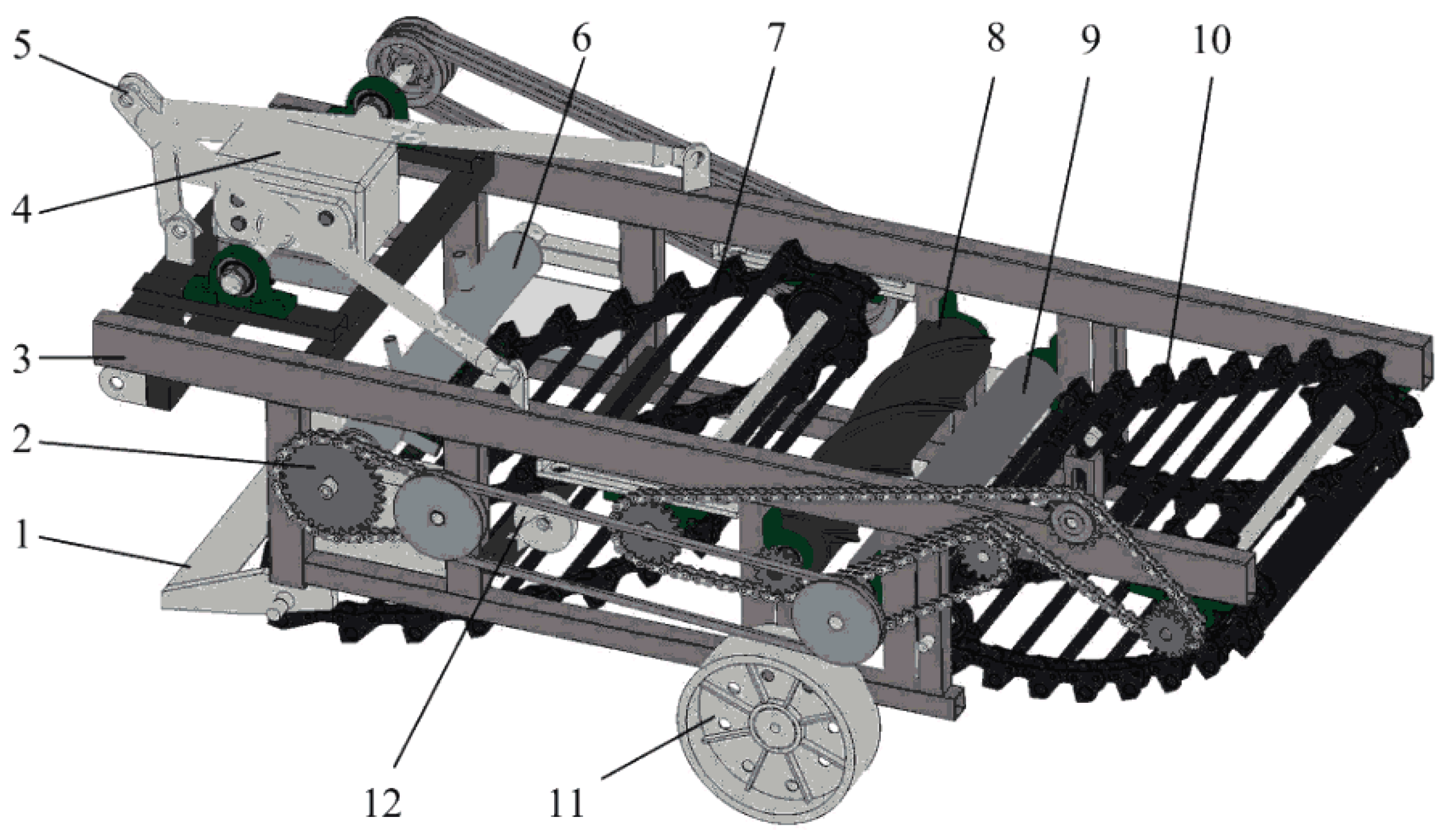
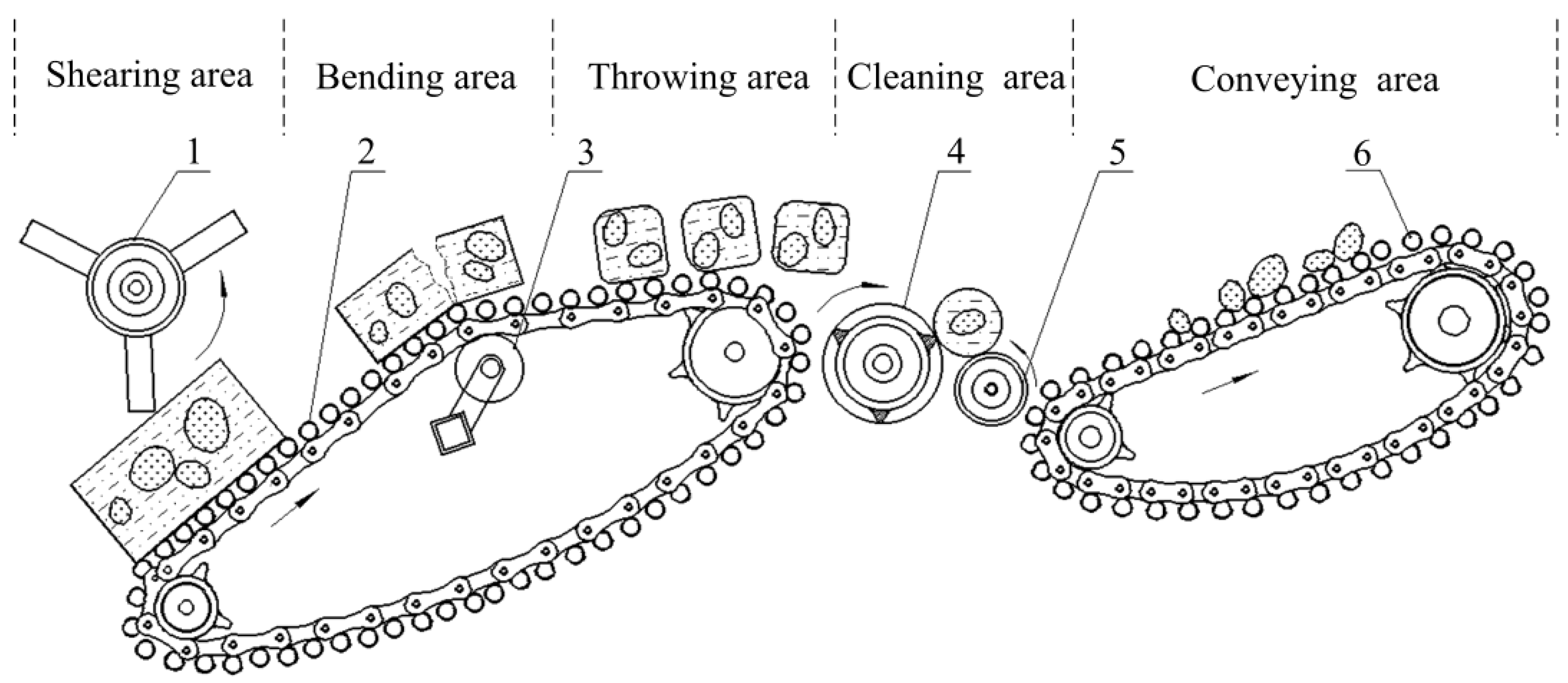
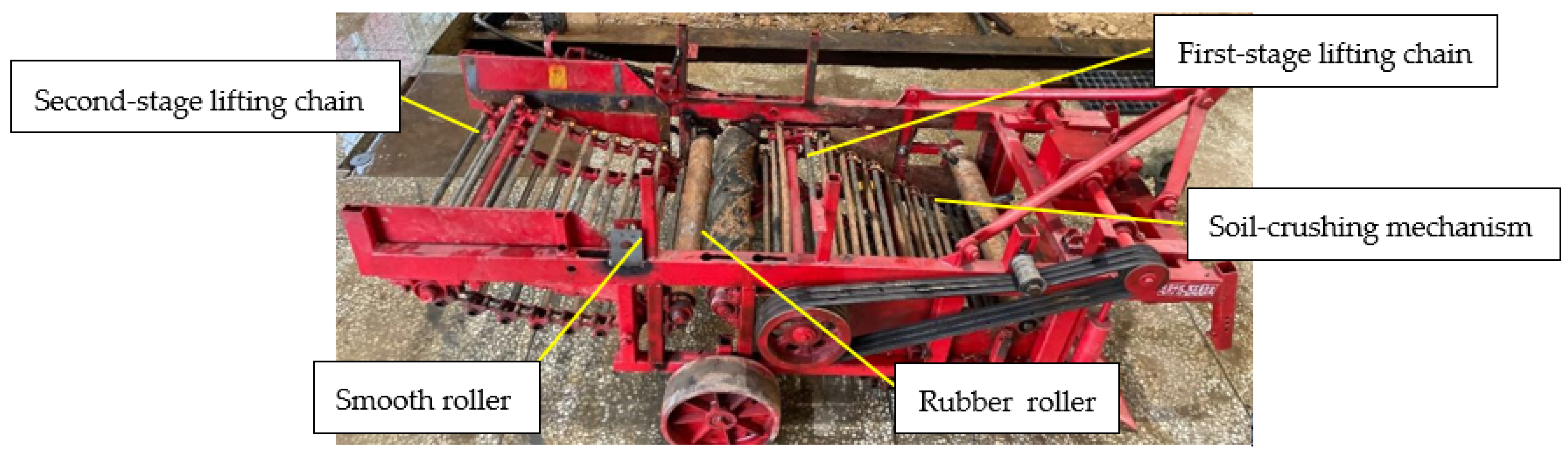
2. Structure and Working Principle

To address the mentioned problems (e.g., soil with high moisture content, large viscosity and poor separation efficacy) in the harvesting process for winter idle paddy fields of Southern China, a new type of potato harvester was designed. Figure 1 shows the 3D model built with Solidworks.
The potato-soil separation device is the most important part of the harvester which mounted at the rear of the digging shovel, comprising a soil-crushing mechanism, a first-stage lifting chain, a debris-cleaning mechanism, as well as a second-stage lifting chain. A rotating roller filled with a hard tooth was mounted on the first-stage lifting chain, and the direction of rotation was counterclockwise. On the whole, the mechanism of the lifting chain with first-stage and second-stage lifting chains comprised chain rods with a particular gap. A support wheel was provided on the bottom of the first-stage lifting chain to form a bulge of chain face, and the second-stage lifting chain was located at the back end of the potato-soil separation device. The debris-cleaning mechanism was mounted in the middle between the first-stage and second-stage lifting chains, which comprised a rubber roller and smooth roller with relative rotation. Furthermore, the spiral-shaped prism was provided on the rubber roller.
Figure 2 is a schematic diagram of the separation device abstracted from the 3D model by using AutoCAD (Autodesk Inc., San Rafael, CA, USA), which illustrates the operating principle of the potato-soil separation device.
By complying with the different action modes of the machine on the potato-soil mixture, the functional areas can fall into five types, i.e., shearing, bending, throwing, cleaning, and conveying. The potato-soil mixture was dug by digging shovel and then transferred to the potato-soil separation device. In the shearing area, the potato-soil mixture was broken initially by the shearing and collision of a rotating roller filled with a hard tooth. In the bending area, when the potato-soil mixture moved to the bulge of the chain face, bending deformation and failure could be generated by gravity action. In the throwing area, the potato-soil mixture was thrown up as impacted by the movement of the first-stage lifting chain, and it was collided and then dispersed when falling. In the cleaning area, the gripping force was determined by the relative rotation between the rubber roller and the smooth roller to clean the inclusion of the flexible haulm and mulching film. Moreover, the potatoes and large soil blocks were continuously transported backwards. In the conveying area, the potatoes, large soil blocks, and stones were transported backwards and fell on the field through a second-stage lifting chain.

3. Key Component Parameter Design and Analysis

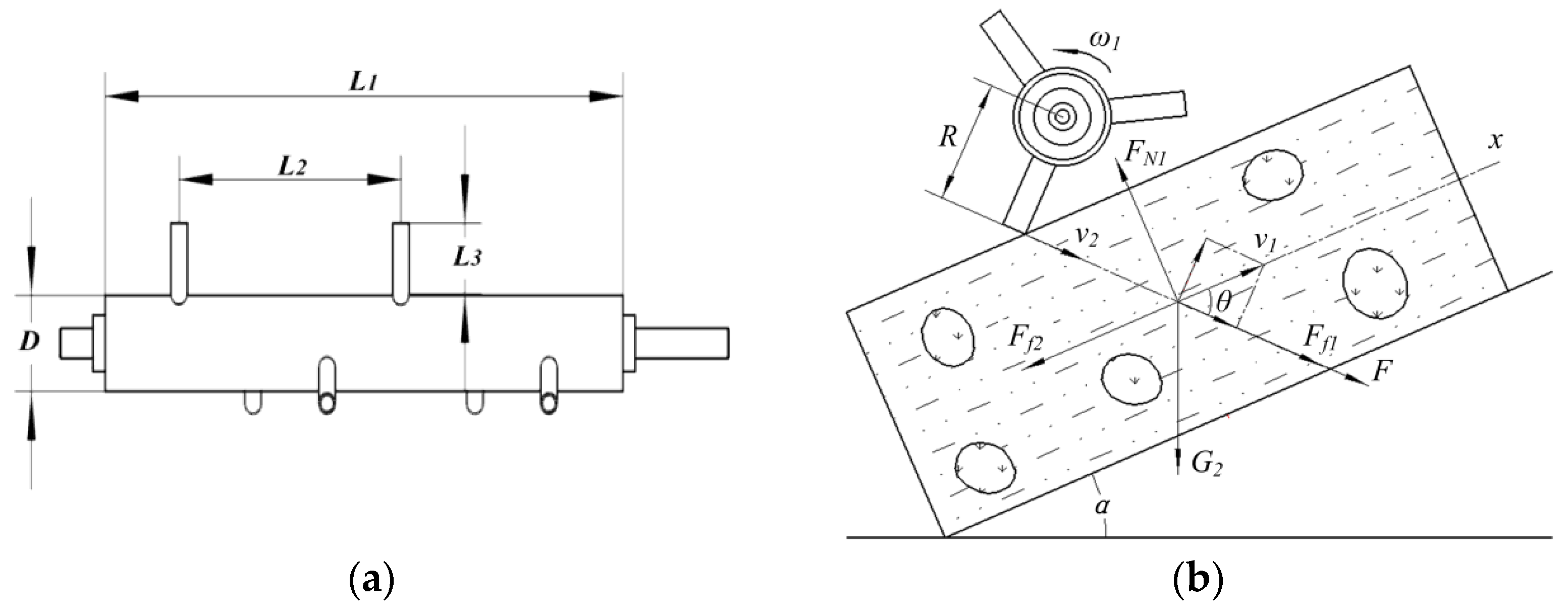
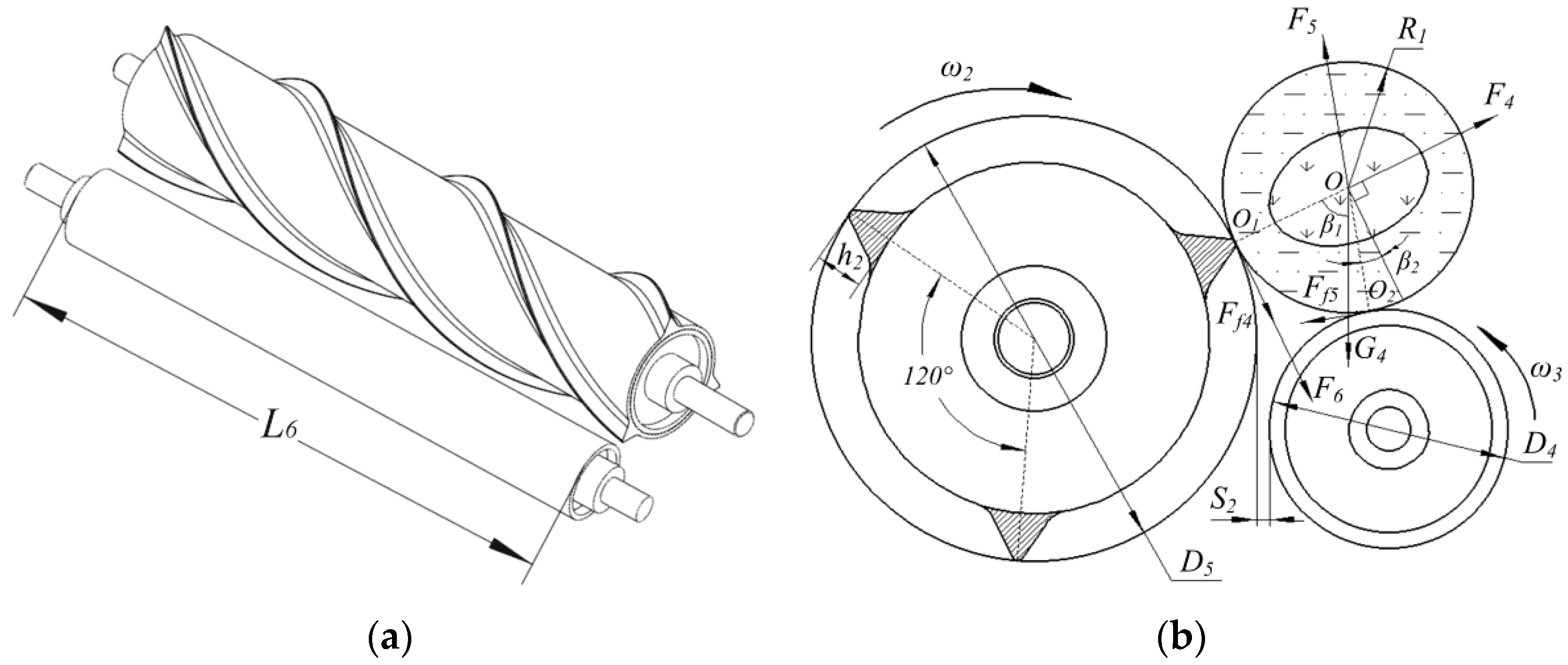
3.1. Parameters of Soil-Crushing Mechanism and Kinetic Analyses during Shearing Area

According to Figure 3a, the soil-crushing mechanism consisted of an installing axis, a roller core, as well as a roller tooth. Its principal effects were the striking and shearing on potato-soil mixture. Moreover, the potato-soil mixture was transported, backward assistant. As indicated from existing studies, the broken soil effect and the degree of potato damage were impacted by parameters of the soil-crushing mechanism (e.g., the tooth number of roller and the spacing between teeth) [31,32]. Accordingly, the soil-crushing mechanism with a roller core length of 630 mm (L1), a roller core diameter of 80 mm (D) and six roller tooth lengths of 60 mm (L3) were set. To ensure the homogeneity of force and crushing, three rows of roller teeth were aligned uniformly and circumferentially with an included angle of 120° between rows. Two adjacent rows were arranged in a misaligned axial direction, and the distance between adjacent teeth in the identical line was set to 115 mm (L2). According to the field study, the potato tubers were planted at a depth of 150 mm, and the growth of the tubers range was nearly 100 mm [33]. Thus, the potato-soil mixture exhibiting a height of approximately 150–200 mm was transported to the potato-soil separation device after being dug by a digging shovel. For this reason, the distance adjustable between the roller tooth tip and the surface of the first-stage lifting chain was set to 80–150 mm.
The potato-soil mixture was transported backwards on the first-stage lifting chain after being dug with a digging shovel. In Figure 3b, when the potato-soil mixture passed over the surface of the first-stage lifting chain beneath the soil-crushing mechanism, the potato-soil mixture would be broken and transported backward efficiently as impacted by the striking and shearing of rotarod roller tooth. The friction force (Ff1) and shear force (F) were applied to the potato-soil mixture since the roller tooth was partially cut into the soil when the roller tooth was in contact with the potato-soil mixture. The potato-soil mixture slides backward relative to the chain surface due to the driving force of roller teeth. Moreover, the potato-soil mixture was subjected to gravity (G1), and friction force (Ff2) and supporting force (FN1) of the chain surface. Shear force (F) was calculated by:
F = M R = Δ v J R 2
From Figure 3:
{ Δ v = v 2 v 1 cos θ v 2 = ω 1 R
Shear force (F) was calculated by Equations (1) and (2):
F = ( ω 1 R v 1 c o s θ ) J R 2
where F denotes the shear force applied from the roller tooth, N; M represents the moment of momentum when the soil-crushing mechanism rotated, N·m; R expresses the radius when the soil-crushing mechanism rotated, m; v1 denotes the linear speed of the first-stage lifting chain, m/s; ω1 represents the angular velocity of the crushing roller, rad/s; v2 expresses the linear velocity at the tip of the soil-crushing roller tooth, m/s; J is the moment of inertia of the soil-crushing mechanism; θ is the angle between the linear speed of the first-stage lifting chain and the shear force (F), °.
Besides the shearing, the potato-soil mixture was further impacted by thrust ( F x ) upward following the chain surface. The equation of resultant force by complying with the linear velocity direction of the first-stage lifting chain for the calculation is written as.
Σ F x = ( F + F f 1 ) cos θ G 1 sin α F f 2
where Ff1 denotes the friction force between the roller tooth and the potato-soil mixture, N; Ff2 represents the friction force between the first-stage lifting chain and the potato-soil mixture, N; G1 expresses the gravity of the potato-soil mixture, N; α is the inclination angle of lifting chain, °.
Equations (3) and (4) indicate that the shear force and thrust on the potato-soil mixture are correlated with the inclination angle of the lifting chain (α), the linear speed of the first-stage lifting chain (v1), and the angular velocity of the soil-crushing roller (ω1).

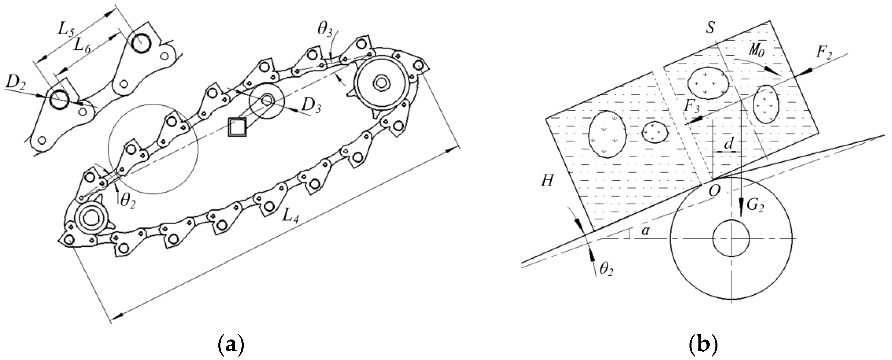
3.2. Parameters of First-Stage Lifting Chain and Kinetic Analyses during Bending Area

As presented in Figure 4a, the first-stage lifting chain consisted of a support wheel, chain rod, chain and sprocket, and its principal effects consisted of vibration, bending, sieving, and delivery. In this study, the length of the first-stage lifting chain was 980 mm (L4), and a support wheel of 100 mm diameter (D3) was mounted under the first-stage lifting chain to form a bulge-shaped domain on the upper chain surface. The angle of a front bulge of 4.26° (θ2) and angle of behind bulge of 7.67° (θ3)as indicated after the position of the support wheel was fixed. The chain rods of the lifting chain were arranged in equal spacing, and its principal effect was the sieving of small soil blocks during transportation. Accordingly, the separation efficacy was impacted by the gap between chain rods. As revealed from the field study, the diameter of winter potatoes during the harvest period in South China was generally more than 40 mm. For this reason, the diameter of the chain rod of 15 mm (D2), the wheelbase of 50 mm (L5), and the spacing of 35 mm (L6) were set.
The first half of the potato-soil mixture hung due to a chain bulge formed by the support wheel when the potato soil mixture passed via the support wheel, and the potato-soil mixture was snapped by gravity at the point O. The force situation of the first half of the potato-soil mixture was sketched in Figure 4b.
M O = G 2 d = 1 2 m g [ S cos ( α + θ 2 ) H sin ( α + θ 2 ) ]
where M0 denotes the crushing moment, N·m; G2 represents the gravity of the first half of potato-soil mixture, N; d expresses the distance between point O and gravity G2, m; m denotes the mass of the first half of potato-soil mixture, kg; H represents the thickness the potato-soil mixture, m; S expresses the length of the first half of potato-soil mixture, m; α represents the inclination angle of lifting chain, °; θ2 is the angle of the front bulge, °.
If the potato-soil mixture was snapped, its crushing moment would be more significant than the adsorption moment of internal force. The equation is as follows:
M O 1 2 F 2 H + 1 2 F 3 H
where F2 denotes the force of the surrounding objects on the potato-soil mixture, N; F3 represents the soil cohesion force, N.
The mass and length of the first half of the potato-soil mixture and crushing moment increased since the potato-soil mixture was delivered backward. The potato-soil mixture was designated as snapping when the crushing moment was more significant than the adsorption moment of internal force.
Equation (6) shows that the magnitudes of the crushing moment were impacted by the inclination angle of the lifting chain (α) and the angle of the front chain bulge (θ2), and the angle of the front chain bulge is tiny and negligible.

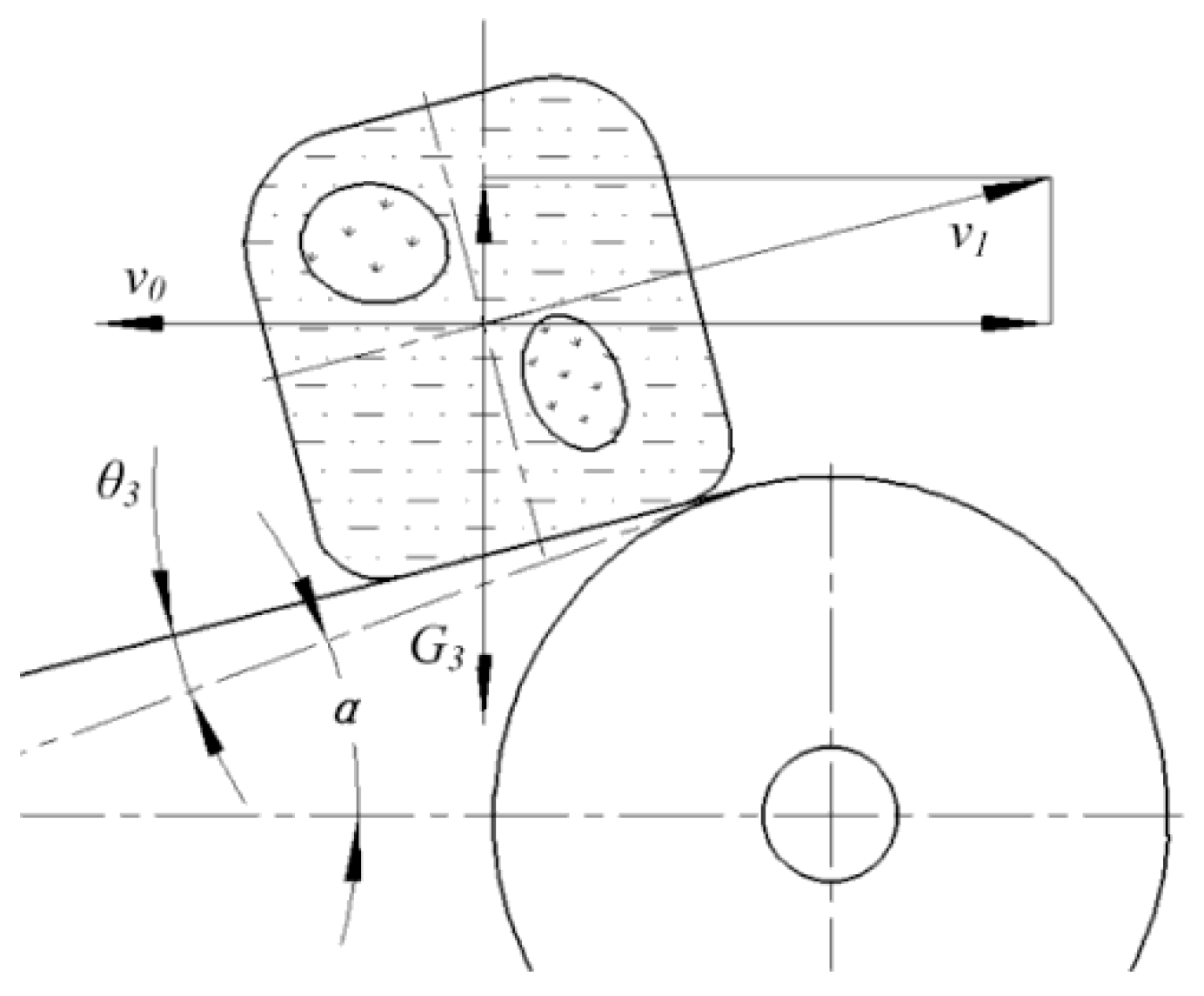
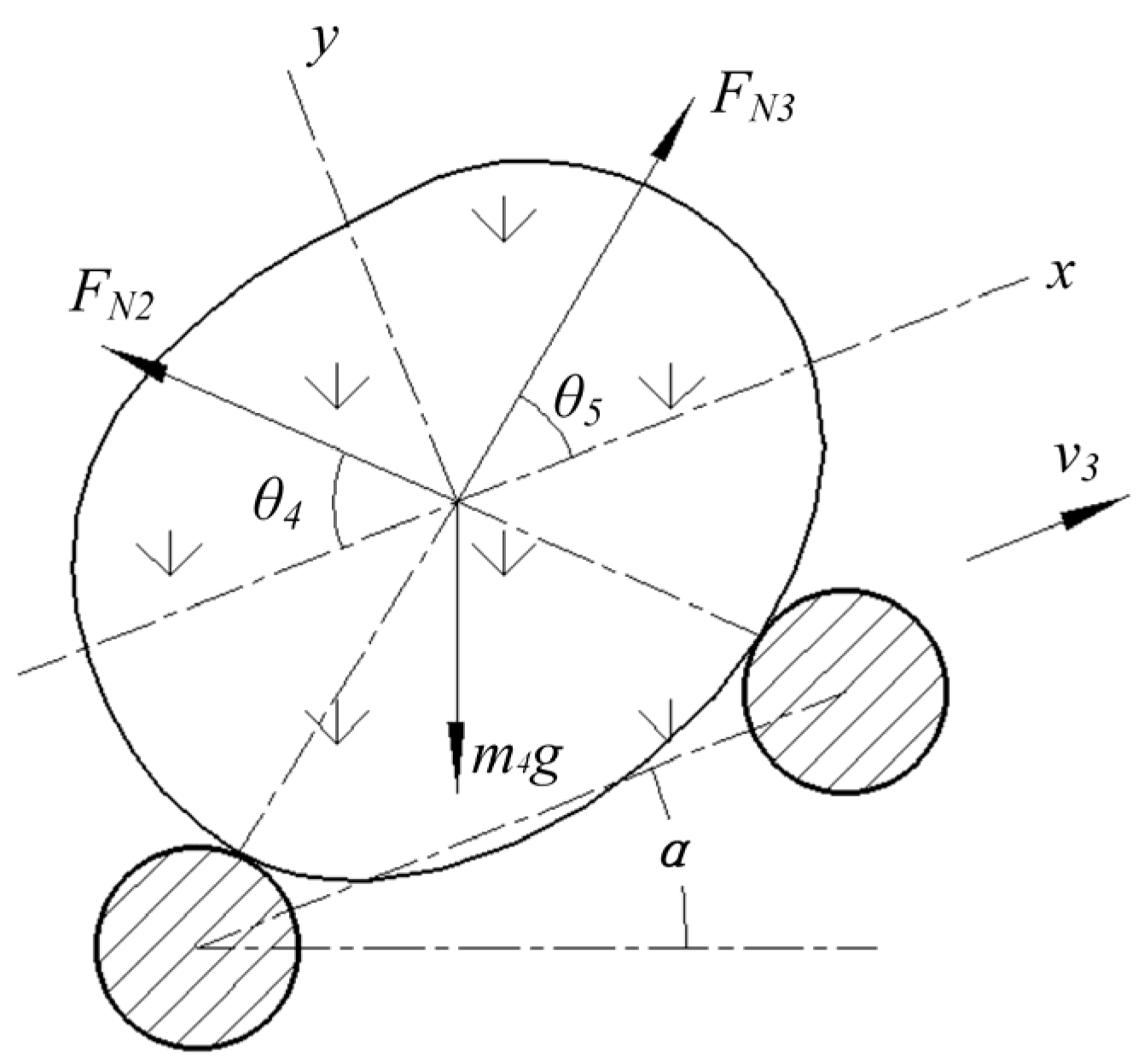
3.3. Kinetic Analyses during Throwing Area

After the first-stage lifting chain, the potato-soil mixture was thrown up, and the potato-soil mixture was then collided after falling and crushed further. To be specific, throwing height acted as a vital factor in collision-crushing degree. As presented in Figure 5, a linear velocity was v1 when the potato-soil mixture left the first-stage lifting chain. The energy conservation equation in the vertical direction was expressed as:
G 3 h = 1 2 m 2 v 1 2 sin 2 ( α θ 3 )
where G3 denotes the gravity of potato-soil mixture, N; h represents the throwing height, m; m2 expresses the mass of potato-soil mixture, kg; v1 denotes the linear speed of the first-stage lifting chain, m/s; α is the inclination angle of lifting chain, °; θ3 is the angle of behind bulge, °.
The throwing height was yielded from Equation (7):
h = v 1 2 sin 2 ( α θ 3 ) 2 g
Equation (8) indicates that the throwing height of potato-soil mixture was impacted by the inclination angle of lifting chain (α), the angle of behind chain bulge (θ3), and the linear speed of the first-stage lifting chain (v1). Besides, the angle of front chain bulge was tiny and negligible.

3.4. Parameters of Debris-Cleaning Mechanism and Kinetic Analyses during Cleaning Area

Winter potatoes in southern China are primarily planted with grass and film mulching [34]. In the mechanical harvesting, other than soil and potatoes, weeds and broken mulch film were mixed. To clean the flexible haulm and mulch, a debris-cleaning mechanism was designed. According to Figure 6a, a debris-cleaning mechanism consisted of a rubber roller and smooth roller with relative rotation. Its principal effect was cleaning the inclusion of the flexible haulm and mulch. Moreover, the potato-soil mixture was transported backward. For the debris-cleaning mechanism, the rubber roller and smooth roller were 630 mm in length (L6), with a gap of 5 mm (S2), and the smooth roller diameter was 75 mm (D4), and the rubber roller diameter was 140 mm (D5). On the rubber roller surface, three prisms aligned in a spiral line were set. The pitch of the helix was equated with the length of the roller (L6), and the prism height (h2) was 15 mm. The convex prisms were aligned uniformly and circumferentially with an included angle of 120° between the adjacent prisms. Furthermore, the cross-section was an isosceles triangle.
Under the debris-cleaning mechanism, to ensure an uneventful delivery of the potato-soil mixture, the kinetic analyses of the potato-soil mixture were performed. According to Figure 6b, the potato-soil mixture on the debris-cleaning mechanism was assumed as a sphere with radius R1 and fell between the rubber roller and smooth roller through the first-stage lifting chain throwing. The frictions were expressed as:
{ F f 4 = F 4 μ F f 5 = F 5 μ
where Ff4 denotes the friction between potato-soil mixture and rubber roller, N; Ff5 represents the friction between potato-soil mixture and smooth roller, N; F4 expresses the support force of the rubber roller to the potato-soil mixture, N; F5 denotes the support force of the smooth roller to the potato-soil mixture, N; μ represents friction coefficient between potato-soil mixture and rubber roller; μ is friction coefficient between potato-soil mixture and smooth roller.
The collision force (F6) applied to the potato-soil mixture was expressed as:
F 6 = 2 M 2 D 5 = 2 ω 2 J 2 D 5
where M2 denotes the moment of momentum when the rubber roller rotates, N·m; D5 expresses the diameter of rubber roller, m; ω2 is the angular velocity when the rubber roller rotates, rad/s; J2 is the moment of inertia of the rubber roller.
According to Figure 6b, the potato-soil mixture rotated backwards around position O2. The rotational centrifugal forces of rubber roller and smooth roller were disregarded, and the moment equation for point O2 was expressed as:
Σ M O 2 = F 4 R 1 cos β 2 R 1 ( F f 4 + F 6 ) ( 1 sin β 2 ) G 4 R 1 cos ( β 1 + β 2 )
where G4 denotes the gravity of potato-soil mixture, N; R1 represents the radius of potato-soil mixture, m; β1 represents the inclination angle between the gravity (G4) and the connecting line OO1, °; β2 expresses the inclination angle between the supporting force (F5) and the straight line passing through the point O and perpendicular to the connecting line OO1, °.
The necessary conditions for an uneventful delivery of the potato-soil mixture were M O 2 0 and F O O 1 0 . The following equations can be yielded combining Equations (9)–(11):
Σ M O 2 = F 4 R 1 [ cos β 2 μ ( 1 sin β 2 ) ] 2 R 1 ω 2 J 2 D 5 ( 1 sin β 2 ) G 4 R 1 cos ( β 1 + β 2 ) 0
Σ F O O 1 = F 4 G 4 sin β 1 + F 5 ( sin β 2 μ cos β 2 ) 0
The conveying capacity of the cleaning agency is determined by the correlation between rubber roller position and smooth roller position, rotating speed of rubber roller and the friction coefficients between the potato-soil mixture and different rollers, besides the weight of the potato-soil mixture.

3.5. Parameters of The Second-Stage Lifting Chain and Kinetic Analyses during the Conveying Area

In this study, the second-stage lifting chain was performed similarly to the first-stage lifting chain presented above. The size of the chain rod and the inclination angle of the lifting chain were identical to those of the first-stage lifting chain, and the length of the second-stage lifting chain was 630 mm (L7).
A handful of loam and potato tubers were transported onto second-stage lifting chain by the debris-cleaning mechanism, and the force situation of the potato tuber was sketched in Figure 7.
The initial speed of the potato falling on the ascending chain was assumed as 0, and the second-stage lifting chain moved backward at a constant speed v2. The potato tubers went through two phases, the acceleration and uniform speed phase. At the acceleration phase, the following conditions in X direction were required to prevent potato damage due to tumbling on the lifting chain:
F N 3 cos θ 5 F N 2 cos θ 4 m 4 g sin α m 4 v 3 t
where FN2 denotes the supporting force of the upper chain rod on the potato tuber, N; FN3 denotes the supporting force of the lower chain rod on the potato tuber, N; θ4 is the angle between the x direction and the supporting force (FN2), °; θ5 is the angle between the x direction and the supporting force (FN3),°; m4 denotes the mass of the potato tuber, kg; α represents the inclination angle of lifting chain, °; v3 expresses the linear velocity of second-stage lifting chain, m/s; ∆t expresses the acceleration time of potato tuber, s.
At the uniform speed phase, the balance equations of potato tuber were obtained separately in X and Y directions.
{ F N 3 cos θ 5 F N 2 cos θ 4 m 4 g sin α = 0 F N 3 sin θ 5 + F N 2 sin θ 4 m 4 g cos α = 0
Equations (14) and (15) indicate that the acceleration and transportation process of potato tubers on the second-stage lifting chain were impacted by θ4, θ5, α, and v3, and the θ4, θ5 are correlated with the potato tuber shape and chain rod size. In addition, the α and v3 are the structure and operating parameters of the lifting chain, respectively.

4. Separation Device Performance Test

4.1. Test Materials and Equipment

The separation test was performed in the laboratory to examine the effect of the device on potato-soil separation and optimize the run parameters. The various parameters of winter potato-soil mixture in the maturity period were investigated by the research team to resemble the actual field potato-soil mixture closely. As revealed from the result, the soil hardness of the upper potato soil mixture (0–10 cm) was 155.2 KPa, that of the lower potato soil mixture (10–20 cm) in the mature period reached 665.3 KPa, the bulk density of potato-soil mixture was 0.98 g/cm3, the potato content was 6.30 × 10⁻³ g/cm3, and the root content was 1.03 × 10⁻⁴ g/cm3 in dry matter.
Several fresh potatoes, roots (15.03% moisture content), and soil (18%, 23% and 28% moisture content) were employed as the experimental materials. The samples bin (height: 20 cm; width: 30 cm; length: 50 cm; volume: 30,000 cm3) was employed to prepare an artificial potato-soil mixture sample. The mixture was loaded into the samples bin, and the sample was compacted to achieve corresponding values of soil hardness of the upper and lower layers. The soil mass, potato tuber, and root in samples with different moisture contents were determined by complying with the field research results, and the result is listed in Table 1. Figure 8 presents the prepared samples of potato-soil mixture.
The potato-soil separation device is illustrated in Figure 9. The potato-soil separation experiment was performed in situ by driving power machinery. For the respective test, the prepared potato-soil mixture was first placed at the front end of the first-stage lifting chain to run the machine to separate the potato-soil mixture.

4.2. Assessment Index

The machine performance standards (good or bad) were defined by complying with the separation effect during the harvest process. Moreover, the more minor the potato tuber damage, the better it would be. Three indicators (i.e., percentage of small soil λ, the percentage of soil adhering to potato tuber γ, and damage rate of potato tuber K) were developed to assess the separate effect of potato-soil separation device while in indoor testing. Two of them (λ and γ) were used to assess the effect of potato-soil separation, and the remaining one (K) was adopted to assess the degree of potato damage. The specific role and calculation method are defined below.
Percentage of small soil λ was primarily used to assess the crushing degree of potato-soil mixture. The soil whose diameter was smaller than the spacing between chain rods fell from between the rods of the lifting chain to separate potato-soil mixture when the potato-soil separation device operated. The soil whose diameter was smaller than the spacing between chain rods (L6 = 35 mm) in each direction was defined as small soil after separation. The percentage of small soil λ was expressed as:
λ = m 5 M S × 100 %
where λ denotes the percentage of small soil, %; m5 represents the mass of small soil after separation, kg; MS expresses the total soil mass in the potato-soil mixture before separation, kg.
The potato tuber remained to bond with portions of the soil after potato-soil separation, so the percentage of soil adhering to potato tuber (γ) was employed to assess the cleaning degree of potato tuber, as expressed below:
γ = m 6 M S × 100 %
where γ denotes the percentage of small soil, %; m6 represents the percentage of soil adhering to potato tuber, kg.
The damage rate of potato tuber (K) was largely adopted to assess the degree of potato damage. The formulations are presented in Equation (22).
K = m 7 M P × 100 %
where K is the damage rate of potato tuber, %; m7 is the mass of potato tuber with damage after separation, kg. MP is the total potato mass in the potato-soil mixture before separation, kg.

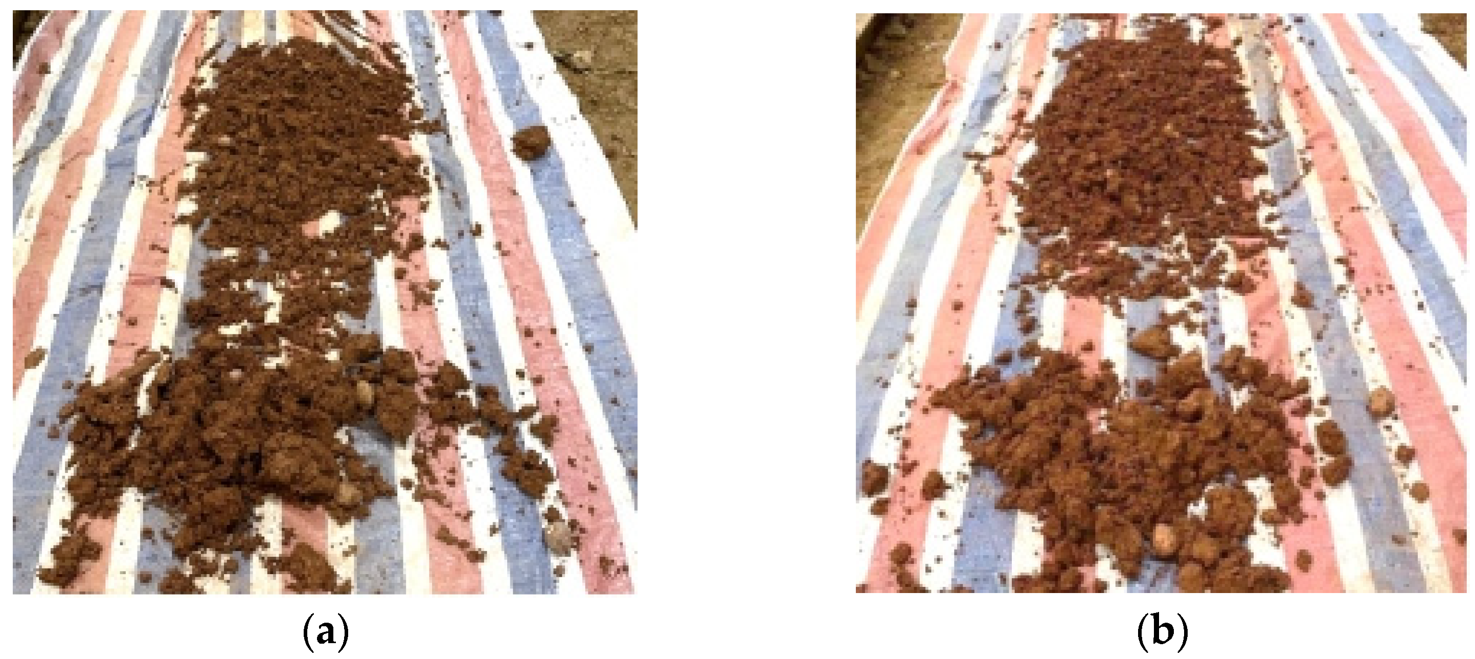
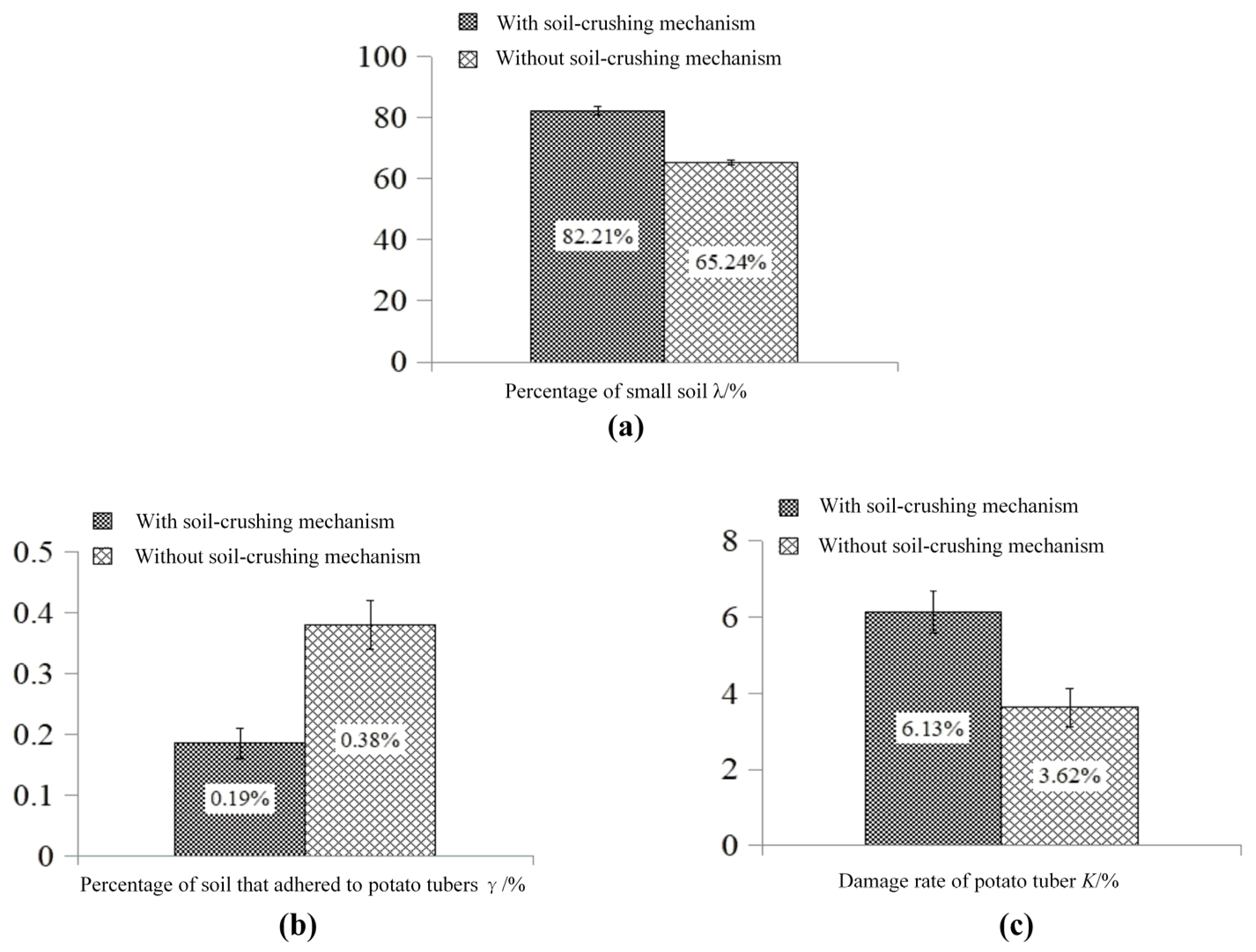
4.3. Testing Operation-Efficacy of Soil-Crushing Mechanism

4.3.1. Test Method

The soil-crushing mechanism is one of the key apparatuses for assisted crushing. To verify the effectiveness of the soil-crushing mechanism and assess the effect, a single factor test with or without a soil-crushing roller was performed. For a single-factor test, the potato-soil mixture with 23% moisture content was selected as test material, and the inclination angle of the lifting chain was set at 15°, the linear speed of the second-stage lifting chain at 0.99 m/s, and rotational speed of the soil-crushing roller at 70 r/min. The respective trial in scenarios with or without a soil-crushing roller was repeated twice. Subsequently, small soil, soil adhered to potato tuber and damaged potato tuber, was picked out manually and weighed to calculate the percentage of small soil λ, the percentage of soil adhering to potato tuber γ, and damage rate of potato tuber K.

4.3.2. Test Result

The separation effect in scenarios with or without any soil-crushing mechanism is shown in Figure 10.
The statistical comparison of the respective assessment index in scenarios with or without any soil-crushing mechanism is shown in Figure 11.
According to Figure 11, the use of a soil-crushing mechanism increased the separation effect for the potato-soil mixture. With the soil-crushing mechanism disassembled, the percentage of small soil λ took up 65.24%. The percentage of small soil λ increased to 82.21%, and the percentage of soil adhering to potato tuber γ decreased to 0.19% from 0.38% after the soil-crushing mechanism was mounted. It was therefore indicated that the soil-crushing mechanism elevated the shattering degree of the potato-soil mixture, thereby indirectly prompting soil sieving in the subsequent cleaning and conveying processes.
Besides, the use of a soil-crushing mechanism up-regulated the damage degree of potato tuber. The damage rate of potato tuber K reached 6.13% after the soil-crushing mechanism was mounted. When the soil-crushing mechanism was disassembled, the damage rate of potato tuber K declined to 3.62%, thereby indicating that the collision injury of partial potatoes was caused under the impact and shearing of soil-crushing mechanism.

4.4. Orthogonal Test

4.4.1. Test Method

Given the kinetic analysis of five functional areas of potato-soil separation device as presented above, the moisture content of potato-soil mixture, the rotational speed of the soil-crushing mechanism, the inclination angle of lifting chain, and the linear velocity of second-stage lifting chain were adopted as the test factors. Specific instructions are presented below:
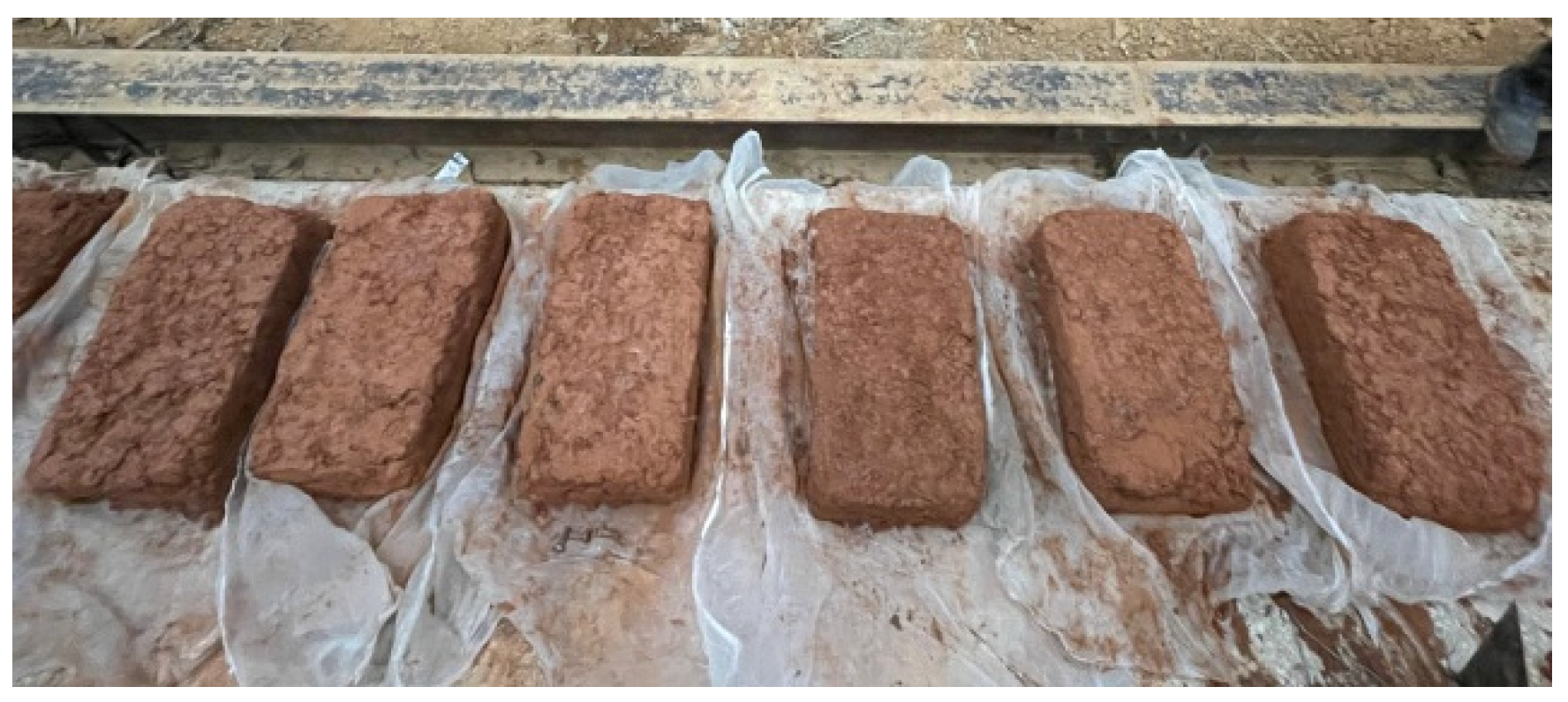
  • The moisture content of potato-soil mixture. In this study, to harvest winter potatoes in idle paddy fields of Southern China, a potato-soil separation device was developed. The main reason for affecting harvesting quality was soil exhibiting a high water capacity in idle paddy fields. Thus, to examine the effect of the different moisture content on the separation effect of potato-soil separation device, the potato-soil mixture involving three different moisture contents (i.e., 18%, 23%, and 28%) was prepared as described in Section 4.1. for the separation test.
  • The rotational speed of the soil-crushing mechanism. The rotational speed of the soil-crushing mechanism impacted the soil-crushing quality and the damage degree, as determined by the kinetic analysis of potato-soil mixture in the shearing area. The rotational speed of the soil-crushing mechanism was adopted as one of the orthogonal test factors to identify optimal running parameters of the soil-crushing mechanism. During the trial, three levels of the rotation speed of the soil-crushing mechanism were set to 70 r/min, 122 r/min, and 175 r/min, respectively. The linear velocity at the tip of the soil-crushing roller tooth was equated with that of the first-stage lifting chain at the rotation speed of the soil-crushing mechanism as 70 r/min.
  • The inclination angle of lifting chain. The inclination angle of the first-stage lifting chain set in this separation device was equated with that of the second-stage lifting chain. Given the kinetic analysis, as previously described, the inclination angle of the lifting chain had effects on the force and motion state of potato-soil mixture in the shearing area, the bending area, the throwing area, and the conveying area to identify the optimal inclination angle of lifting chain, that was employed as one of the orthogonal test factors. During the trial, three levels of the inclination angle of lifting chain were set to 15°, 20°, and 25°, respectively.
  • The linear velocity of second-stage lifting chain. The linear velocity of second-stage lifting chain impacted the force and motion state of potato-soil mixture, as determined by the kinetic analysis of potato-soil mixture in the conveying area. To identify optimal linear velocity of second-stage lifting chain, that acted as one of the orthogonal test factors. During the trial, three levels of the linear velocity of the second-stage lifting chain were set to 0.75 m/s, 0.99 m/s, and 1.23 m/s, respectively.
As described in Section 4.2., the percentage of small soil λ, percentage of soil adhered to potato tuber γ, and damage rate of potato tuber K still were taken as evaluation indexes in this orthogonal test. The L34 orthogonal table was used to arrange the experiment, and the orthogonal test scheme was given in Table 2 below.

4.4.2. Analysis of Orthogonal Test Results
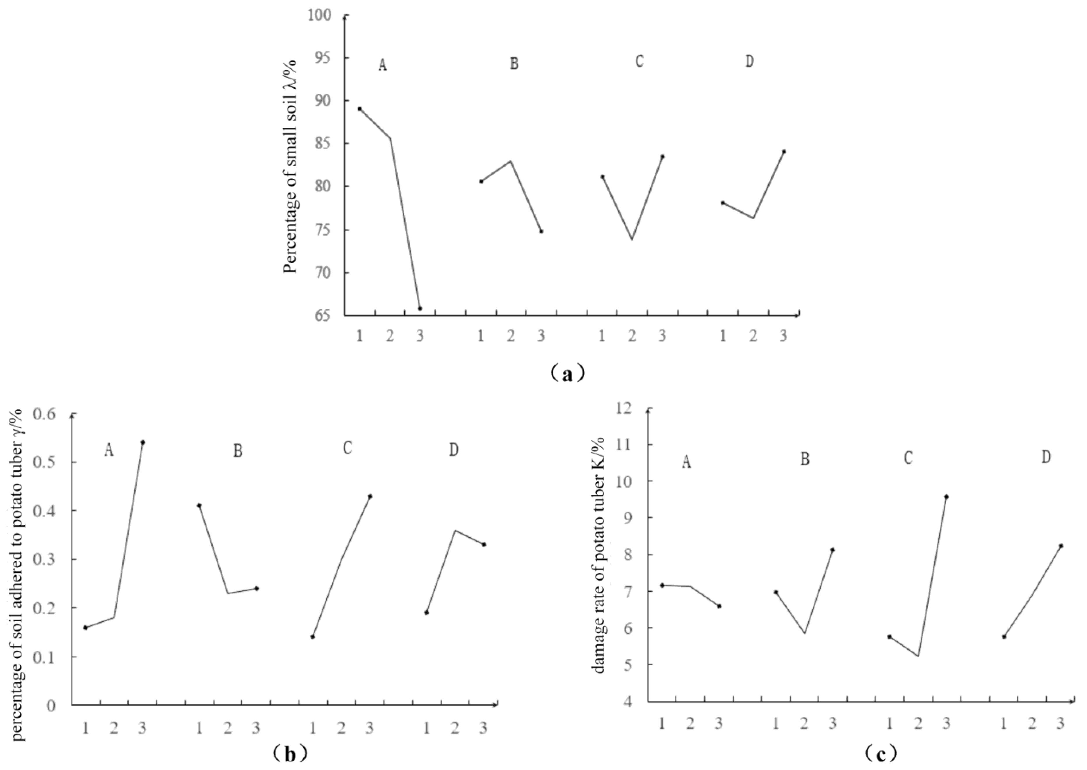
Range Analysis

To examine the primary and secondary sequence and the optimal lever of the respective factor, the range analysis for orthogonal test results (Table 3) was conducted, and the means graph (Figure 12) of a distinct index at the individual level of each factor was plotted.
As indicated from the mentioned results: for the percentage of small soil λ, the moisture content was the main factor because it had the maximal range value, and the higher the moisture content, the smaller the percentage of small soil would remain. The effect order of the respective factor to λ was as: moisture content>linear velocity of second-stage lifting chain > rotational speed of the soil-crushing mechanism> inclination angle of lifting chain.
For the percentage of soil adhering to potato tuber γ, the moisture content was the main factor since it had maximum range value, and the higher the moisture content, the bigger the percentage of soil adhering to potato tuber would be. The effect order of the respective factor to γ was moisture content > linear velocity of second-stage lifting chain > rotational speed of the soil-crushing mechanism > inclination angle of lifting chain.
For the damage rate of potato tuber K, the linear velocity of second-stage lifting chain acted as the main factor since it achieved the maximal range value. The effect order of the respective factor to K was linear velocity of second-stage lifting chain > inclination angle of lifting chain>rotational speed of the soil-crushing mechanism>moisture content.

Analysis of Variance

Based on the range analysis, the variance analysis was conducted to study whether the various factors exerted a statistically significant influence on each assessment index. Given the results of range analysis, the factor exerting the minimal influence on the assessment index served as a residual term during variance analysis, and the results are listed in Table 4.
From the mentioned results: for a percentage of small soil λ, a confidence interval that factor A significantly impacted λ was at 90–95%, thereby illustrating that statistically the moisture content significantly impacted the percentage of small soil, and other factors were not significant for λ due to a confidence interval below 80%. For the percentage of soil adhering to potato tuber γ, a confidence interval that the factor A exerted some effects on γ was at 80–90%, which illustrated statistically that the moisture content had some effect on the percentage of soil adhering to potato tuber. Other factors were not significant for λ because of a confidence interval below 80%. For the damage rate of potato tuber K, the confidence intervals that the factors significantly impacted K were +95% for C, 90–95% for B, 90–95% for C, respectively, which illustrated statistically that the mentioned factors significantly impacted K.
The results of ANOVA indicated that the effect of potato-soil separation was largely impacted by moisture content, and the higher the moisture content, the lower the shattering degree would be; the more the soil adhered to the potato tuber, the lower the cleaning degree of the tuber would be. This was because moisture increased the soil stickiness and improved the difficulty degree of crushing and cleaning. The degree of potato damage was primarily impacted by the structure and run parameters of the potato harvester as impacted by the collision of the machined parts. The linear velocity of the second-stage lifting chain for mechanical parameters exerted the most prominent effect on the damage rate of potato tuber. This was because most of the soil was separated and sieved, and a buffer effect on potatoes decreased or even disappeared when the potatoes were transported to the second-stage lifting chain.

Regression Model

The 3 levels of the respective factor were expressed by −1, 0, and 1, respectively, to study the significance of the effect of each factor on the assessment index and anticipate the outcome of test, and multiple linear regression models were built.
For percentage of small soil λ, the regression equations were yielded as:
λ = 79.4744 11.6317 A 2.925 B + 1.175 C + 2.98 D
N = 9, R = 0.86333, F = 2.92677, S = 8.8873
For the percentage of soil adhering to potato tuber γ, the regression equations were obtained as follows:
γ = 0.2911 + 0.1917 A 0.0833 B + 0.145 C + 0.0683 D
N = 9, R = 0.9, F = 4.26316, S = 0.15624
For the damage rate of potato tuber K, the regression equations were obtained as follows:
K = 6.9667 0.28 A + 0.58 B + 1.725 C + 1.235 D
N = 9, R = 0.7752, F = 1.50581, S = 2.21284

Parameter Optimization and Field Verification

To determine an optimal designing parameter of potato-soil separation device, the multi-objective programming of regression equation as described above was performed. By complying with the practical situation, the constraints K ≤ 4% for damage rate of potato tuber and λ ≥ 90% for a percentage of small soil were determined. The minimum was then obtained through programming by setting the percentage of soil adhering to potato tuber as the programming objective. The programming constraints are presented in Equation (22).
{ 1 A 1 1 B 1 1 C 1 1 D 1 6.9667 0.28 A + 0.58 B + 1.725 C + 1.235 D 4 79.4744 11.6317 A 2.925 B + 1.175 C + 2.98 D 90
The result of programming shows that the minimum value that meets all the constraints was obtained when A = −1, B = −0.865, C = −1, D = −0.8259. Accordingly, the best lever combination was moisture content of 18%; the rotational speed of the soil-crushing mechanism of 84.18 r/min; linear velocity of second-stage lifting chain of 0.75 m/s; and inclination angle of lifting chain of 15.87°.
To demonstrate the validity of the optimization parameters, the potato-soil separation device of the harvester was modified under the optimal lever combination as described above and a field harvesting test was performed in Changsha, Hunan. The moisture content of soil in the field was measured to be 20.06% during the test. The visible potato rate and damage rate of potatoes acted as the assessment indexes based on the method of the China National Standard NY/T 648-2015. An outcome trial was presented for visible potato rate of 94.31% and damage rate of potato of 0.89%. As the national standard requires that the damage rate of potato is less than 1.5%, the performance met the requirement, which illustrated the effectiveness of machine parameter optimization. The modified prototype and the harvesting effect are illustrated separately in Figure 13.

5. Discussion and Conclusions

In this paper, we developed a new type of potato-separation device comprising five function areas (i.e., shearing, bending, throwing, cleaning, and conveying) to address the problem (e.g., potato-soil separation under sticky soils condition). Given the kinetic analyses for the potato-soil mixture of five function areas, the crucial factors of the effect of potato-soil separation were determined. Then the run parameters of the device were optimized by conducting an orthogonal test.
Toothed roller is the key component of the soil-crushing mechanism and was expected to shear the sticky soil. The structure and function of the toothed roller in this paper are somewhat similar to the finger wheel in poke finger’s wheel type potato harvester [24], but the roller in this paper was mounted above the lifting chain, and there is a movement match with the lifting chain, the shear and transport modes of potato-soil complex are different. As revealed from the results of the single factor test, after the soil-crushing mechanism installation, the percentage of small soil λ was increased from 65.24% to 82.21%, which indicated that the shearing and impact effect on potato-soil mixture of soil-crushing mechanism elevated the shattering degree of the potato-soil mixture. However, the use of a soil-crushing mechanism up-regulated the damage degree of potato tuber. The damage rate of potato tuber K declined from 6.13 to 3.62% when the soil-crushing mechanism was disassembled, that we believe is also caused by shearing and striking effect on potato tubers of soil-crushing mechanism.
The results of orthogonal test showed that the optimal run parameters included the rotational speed of the soil-crushing mechanism of 84.18 r/min; linear velocity of second-stage lifting chain of 0.75 m/s and inclination angle of lifting chain of 15.87°. The rotational speed of 84.18 r/min made the linear velocity at the tip of roller tooth slightly faster than that of the lifting chain, which could not only ensure the delivery, but also minimize the impact of roller teeth on potato tubers. According to the results of previous studies, the recommended linear velocity of the lifting chain was found to be at the range of 1.0–2.2 m/s [25,26,27], and the inclination angle at the range of 20–24° [25,27,31]. Lower values of the optimal parameters were obtained in this study. We believe that was caused by the characteristics of paddy clay soil; sticky soil needs longer sieving time so as the delivery velocity should be slower, and the smaller inclination angle will be good for the lifting and sieving of the heavy soil.
The field experiments were performed by the modified potato harvester with the condition of soil moisture content of 20.06%. As revealed from the result, the visible potato rate took up 94.31%; the damage rate of potato was 0.89%. We referred to other studies that were conducted according to the same standard (NY/T 648-2015), the poke finger’s wheel type potato harvester mentioned above was tested in the field, and the visible potato rate was 96.5%; the damage rate of potato was 4.5% [24], while the test conducted in the condition in which the soil moisture content was 12%. In the field test of another crawler self-propelled potato harvester under the condition of 20% soil moisture content, the visible potato rate was 98.54% and the damage rate of potato was 1.31% [35], while the test site is located in northwest of China, where the soil is sandy rather than clay. The results of field experiments show that the visible potato rate was lower when harvest potato in wet and sticky clay soil compared to with sandy soil and dry soil, which was consistent with practical common sense. The potato harvester in this study obtained a lower damage rate of potato, which may be related to the buffering effect of sticky soil. In general, based on the results of field trials, the new type of potato harvester proposed in this paper can meet the requirement of harvesting potato in the sticky heavy soil condition of winter idle paddy fields in south of China.
It should be noted that there are still some limitations in the process of parameter optimization in this study. We simulated the sticky soil condition (i.e., moisture content, soil hardness, bulk density, root content and tuber content) of winter idle paddy fields through a field investigation, and carried out orthogonal experiments under laboratory conditions. However, the actual field operation may also be affected by many other uncontrollable factors (e.g., stones, weeds), so for any specific harvest environment, field test and debugging are necessary.
From what has been discussed above, the primary conclusions are drawn as follows:
(1)
The application of the soil-crushing mechanism with toothed roller improved the separation effect, whereas it caused more potato tuber damage.
(2)
The optimal run parameters of the potato-soil separation device included the rotational speed of the soil-crushing mechanism of 84.18 r/min; linear velocity of second-stage lifting chain of 0.75 m/s and inclination angle of lifting chain of 15.87°.
(3)
As revealed from the result of field experiments, the visible potato rate took up 94.31%, the damage rate of potato was 0.89%, which indicated that the new type of potato harvester proposed in this paper can meet the requirement of harvesting potato in winter idle paddy fields in south of China, and provide equipment support for potato harvest under sticky soils condition.

Author Contributions

Conceptualization, B.W. and F.X.; methodology, B.W.; software, T.H., X.Q. and T.Z.; validation, X.Q., T.Z. and X.W.; formal analysis, B.W., T.H. and X.Q.; investigation, B.W., X.Q. and X.W.; resources, F.X.; data curation, B.W., T.H. and X.Q; writing—original draft preparation, B.W., T.H. and X.Q.; writing—review and editing, B.W. and F.X; visualization, B.W. and T.H.; supervision, F.X.; funding acquisition, B.W. and F.X. All authors have read and agreed to the published version of the manuscript.

Funding

This research was supported by Hunan Provincial Natural Science Foundation of China (Grant number “2019JJ50275”) and Hunan Dry Grain Industry Technology System.

Institutional Review Board Statement

Not applicable.

Informed Consent Statement

Not applicable.

Data Availability Statement

All data are presented in this article in the form of figures and tables.

Conflicts of Interest

The authors declare no conflict of interest.

References

  1. Jian, M.; Luo, Q.; Gao, M. Potato Development Trends, Regional Patterns and Yield Increase Potential in Southern Winter Cropping District. Chin. J. Agric. Resour. Reg. Plan. 2012, 3, 73–79. [Google Scholar]
  2. Jiang, L.; Ma, X.; Wu, T.; Chen, X.; Sun, G.; Tan, Y.; Lu, F.; Chen, G. Application Status and Research Prospect of Southern Winter Planting Potato Harvesting Machine. J. Agric. Mech. Res. 2016, 7, 163–268. [Google Scholar] [CrossRef]
  3. Al-Mallahi, A.; Kataoka, T.; Okamoto, H.; Shibata, Y. Detection of Potato Tubers Using An Ultraviolet Imaging-Based Machine Vision System. Biosyst. Eng. 2010, 105, 257–265. [Google Scholar] [CrossRef]
  4. Bentini, M.; Caprara, C.; Martelli, R. Harvesting Damage to Potato Tubers by Analysis of Impacts recorded with an Instrumented Sphere. Biosyst. Eng. 2006, 94, 75–85. [Google Scholar] [CrossRef]
  5. Bulgakov, V.; Ivanovs, S.; Adamchuk, V.; Ihnatiev, Y. Investigation of The Influence of The Parameters of The Experimental Spiral Potato Heap Separator on The Quality of Work. Agron. Res. 2017, 15, 44–54. [Google Scholar]
  6. Kai, C.; Yanyu, G.; Luqiang, Y.; Yuqing, Z. Design and Simulation Analysis of Vibrating Shovel Potato Harvester. J. Agric. Mech. Res. 2018, 10, 44–50. [Google Scholar] [CrossRef]
  7. Natenadze, N. The Design and Theoretical Justification of A Vibratory Digger Shovel. Mech. Agric. Conserv. Resour. 2016, 62, 9–11. [Google Scholar]
  8. Li, J.; Jiang, X.; Ma, Y.; Tong, J.; Hu, B. Bionic Design of a Potato Digging Shovel with Drag Reduction Based on the Discrete Element Method (DEM) in Clay Soil. Appl. Sci. 2020, 10, 7096. [Google Scholar] [CrossRef]
  9. Cui, G.; Ma, Y.; Yang, D.; Jia, J.; Li, Y. Research Situation of Bionic Resistance Reducing Technology about Potato Digging Shovel. Trans. Chin. Soc. Agric. Eng. 2019, 9, 19–22. [Google Scholar]
  10. Kalinin, A.; Teplinsky, I.; Ruzhev, V. Improvement of Digging Shares of Root Harvesting Machines Based on Rheological Model of Soil State. In Proceedings of the Engineering for Rural Development, Jelgava, Latvia, 26–28 May 2021; pp. 1051–1057. [Google Scholar]
  11. Salem, A.E.; Wang, H.; Gao, Y.; Zha, X.; Abdeen, M.A.; Zhang, G. Effect of Biomimetic Surface Geometry, Soil Texture, and Soil Moisture Content on the Drag Force of Soil-Touching Parts. Appl. Sci. 2021, 11, 8927. [Google Scholar] [CrossRef]
  12. Wei, Z.C.; Li, H.W.; Sun, C.Z.; Su, G.; Li, X. Experiments and Analysis of a Conveying Device for Soil Separation and Clod-Crushing for a Potato Harvester. Appl. Eng. Agric. 2019, 35, 987–996. [Google Scholar] [CrossRef]
  13. Arafa, G. Some Factors Affecting the Damage of Potato Tubers During Harvest. Misr J. Agric. Eng. 2019, 36, 753–772. [Google Scholar] [CrossRef]
  14. Ismail, Z.; Amine, E.; El-Shabrawy, T.; Faleih, H. Investigate A Simple Design for Sweet Potato Harvesting. Misr J. Agric. Eng. 2014, 31, 1331–1346. [Google Scholar] [CrossRef]
  15. Xie, S.; Wang, C.; Deng, W. Displacement Analysis of Potato Relative to Separation Sieve and Separation Sieve Performance Test. J. Agric. Sci. Technol. 2019, 21, 71–81. [Google Scholar] [CrossRef]
  16. Xie, S.; Wang, C.; Deng, W.; Li, X.; Qi, S. Separating Mechanism Analysis and Parameter Optimization Experiment of Swing Separation Sieve for Potato and Soil Mixture. Trans. Chin. Soc. Agric. Mach. 2017, 48, 156–164. [Google Scholar] [CrossRef]
  17. Wei, Z.; Li, H.; Sun, C.; Li, X.; Liu, W.; Su, G.; Wang, F. Improvement of Potato Harvester with Two Segment of Vibration and Wave Separation. Trans. Chin. Soc. Agric. Eng. 2018, 34, 42–52. [Google Scholar] [CrossRef]
  18. Olt, J.; Adamchuk, V.; Korniushyn, V.; Melnik, V.; Kaletnik, H.; Ihnatiev, Y.; Ilves, R. Research into The Parameters of A Potato Harvester’s Potato Heap Distributor, And The Justification of Those Parameters. J. Agric. Sci. 2021, 32, 92–99. [Google Scholar] [CrossRef]
  19. Wei, Z.; Li, H.; Mao, Y.; Sun, C.; Li, X.; Liu, W.; Su, G. Experiment and Analysis of Potato-Soil Separation Based on Impact Recording Technology. Int. J. Agric. Biol. Eng. 2019, 12, 71–80. [Google Scholar] [CrossRef]
  20. Shi, L.; Wu, J.; Zhao, W.; Sun, W.; Wang, D.; Li, H.; Liu, Q. Design and Experiment on Potato Digger of Disc Ce-Grate Type. Trans. Chin. Soc. Agric. Eng. 2012, 28, 15–21. [Google Scholar] [CrossRef]
  21. Yang, R.; Yang, H.; Shang, S.; Ni, Z.; Liu, Z.; Guo, D. Design and Experiment of Vertical Circular Separating and Conveying Device for Potato Combine Harvester. Trans. Chin. Soc. Agric. Eng. 2018, 34, 10–18. [Google Scholar] [CrossRef]
  22. Zizeng, L.; Jinlin, J.; Changling, Z.; Qun, Y.; Xiuxu, S. Design and Experimental Study on The Conveying Chain Soil Cleaning Device of Potato Harvester. J. Agric. Mech. Res. 2016, 2, 123–127. [Google Scholar] [CrossRef]
  23. Kostenko, M.Y.; Ruzimurodov, A.; Byshov, D.; Golakhov, A.; Yakutin, N. Study of Soil Separation at A Potato Chain with A Cross Rotating Agitator. In IOP Conference Series: Earth and Environmental Science, January 2020; IOP Publishing: Bristol, UK, 2020; Volume 422, p. 012032. [Google Scholar] [CrossRef]
  24. Wu, J.; Li, H.; Sun, W.; Huang, X.; Sun, B. Design of Potato Digger in Poke Finger’s Wheel Type. Trans. Chin. Soc. Agric. Mach. 2010, 41, 76–79. [Google Scholar] [CrossRef]
  25. Lü, J.; Sun, H.; Dui, H.; Peng, M.; Yu, J. Design and Experiment on Conveyor Separation Device of Potato Digger Under Heavy Soil Condition. Trans. Chin. Soc. Agric. Mach. 2017, 48, 146–155. [Google Scholar] [CrossRef]
  26. Gao, G.; Xie, H. Numerical Analysis and Simulation of Potato Soil Separation Mechanism Based on EDEM. J. Agric. Mech. Res. 2019, 1, 15–21. [Google Scholar] [CrossRef]
  27. Zhang, Z.; Wang, H.; Li, Y.; Yang, X.; Ibrahim, I.; Zhang, Z. Design and Experiment of Multi-stage Separation Buffer Potato Harvester. Agric. Mech. J. 2021, 52, 96–109. [Google Scholar]
  28. Hevko, R.; Tkachenko, I.; Synii, S.; Flonts, I. Development of Design and Investigation of Operation Processes of Small-Sclale Root Crop and Potato Harvesters. INMATEH-Agric. Eng. 2016, 49, 53–60. [Google Scholar]
  29. McRae, D.; Hutchison, P.; Carruthers, J. Sieving Control and Horizontal Agitation of Potato Harvester Chains. Trans. ASAE 1986, 29, 366–0369. [Google Scholar] [CrossRef]
  30. Zhbanov, N.; Byshow, N.; Kostenko, N.; Rembalovich, G.; Kostenko, M. Improvement of The Working Bodies of The Harvesting Machines by Means of The Use of Composite Materials. In Proceedings of the BIO Web of Conferences, Voronezh, Russian Federation, 17–18 October 2019; EDP Sciences: Les Ulis, France, 2020; Volume 17, p. 00191. [Google Scholar] [CrossRef] [Green Version]
  31. Jia, H.; Ji, W.; Han, W.; Tan, H.; Ma, C. Optimization Experiment of Structure Parameters of Rototilling and Stubble Breaking Universal Blade. Trans. Chin. Soc. Agric. Mach. 2009, 40, 45–50. [Google Scholar]
  32. Jia, H.; Chen, Z.; Hong, G. Study on Working Principle of Rotary Tillage and Stubble Cutting and Design of Universal Knife Roller. Trans. Chin. Soc. Agric. Mach. 2000, 4, 29–32. [Google Scholar]
  33. Li, Y.; Wang, J.; Tang, J.; Wang, E.; Hu, Q. Optimum Planting Date and Cultivar Maturity to Optimize Potato Yield and Yield Stability in North China. Field Crop. Res. 2021, 269, 108179. [Google Scholar] [CrossRef]
  34. Xu, G.; Luo, W.; Li, H.; Xu, Y.; Ji, R.; Tang, H. Plastic Film and Rice Straw Mulching: Effects on Yield and Quality of Winter Potato and Control Efficiency of Weed. Chin. Agric. Sci. Bull. 2021, 37, 13–18. [Google Scholar]
  35. Zhou, J.; Yang, S.; Li, M.; Chen, Z.; Zhou, J.; Gao, Z.; Chen, J. Design and Experiment of A Self-Propelled Crawler-Potato Harvester for Hilly and Mountainous Areas. INMATEH-Agric. Eng. 2021, 64, 151–158. [Google Scholar] [CrossRef]
Figure 1. 3D model of potato harvester. 1—Digging shovel; 2—transmission system; 3—frame; 4—gear box; 5—traction frame; 6—soil-crushing mechanism; 7—first-stage lifting chain; 8—rubber roller; 9—smooth roller; 10—second-stage lifting chain; 11—walking wheel; 12—lifting chain support wheel.
Applsci 11 10959 g001
Figure 2. Schematic diagram of potato-soil separation device. 1—Soil-crushing mechanism; 2—first-stage lifting chain; 3—support wheel; 4—rubber roller; 5—smooth roller; 6—second-stage lifting chain.
Applsci 11 10959 g002
Figure 3. (a) The parameters of the soil-crushing mechanism; (b) The kinetic analyses of potato-soil mixture during the shearing area.
Applsci 11 10959 g003
Figure 4. (a) Structural parameters of the first-stage lifting chain; (b) the force analyses of potato-soil mixture during the bending area.
Applsci 11 10959 g004
Figure 5. Analysis of the throwing process of potato-soil mixture.
Applsci 11 10959 g005
Figure 6. (a) Structural parameters of the debris-cleaning mechanism; (b) the kinetic analyses of potato-soil mixture during cleaning area.
Applsci 11 10959 g006
Figure 7. The kinetic analyses of potato tuber during conveying area.
Applsci 11 10959 g007
Figure 8. Samples of potato-soil mixture.
Applsci 11 10959 g008
Figure 9. Test prototype of potato-soil separation device.
Applsci 11 10959 g009
Figure 10. The separation effect in different scenarios. (a) Without soil-crushing mechanism; (b) with soil-crushing mechanism.
Applsci 11 10959 g010
Figure 11. The statistical comparison of the respective assessment index in different scenarios. (a) Percentage of small soil; (b) percentage of soil that adhered to potato tubers; (c) damage rate of potato tuber.
Applsci 11 10959 g011
Figure 12. Means graph of a different index at the individual level of the respective factor. (a) Percentage of small soil; (b) percentage of soil that adhered to potato tubers; (c) damage rate of potato tuber.
Applsci 11 10959 g012
Figure 13. Field harvesting test. (a) Modified prototype; (b) harvesting effect.
Applsci 11 10959 g013
Table 1. Masses of the individual constituents of samples with different initial moisture contents.
Moisture Content
/%
Volume
/cm3
Soil Mass
/kg
Potato Mass
/g
Root Mass
/g
1830,00035.85 (18% moisture content)61310
2330,00038.18 (23% moisture content)61310
2830,00040.83 (28% moisture content)61310
Table 2. Coding with factors and levels.
LevelsFactors
ABCD
Moisture Content
/%
Rotational Speed of
Soil-Crushing Mechanism
/r·min−1
Linear Velocity of
Second-Stage Lifting Chain
/m·s−1
Inclination Angle of Lifting Chain
1
2
3
18
23
28
70
122
175
0.75
0.96
1.23
15
20
25
Table 3. Results of orthogonal test and range analysis.
Experimental
Number
Experimental FactorAssessment Index
ABCDPercentage of
Small Soil
λ/%
Percentage of
Soil Adhered to Potato Tuber
γ/%
Damage
Rate of Potato
Tuber
K/%
118700.751590.460.025.1
2181220.962083.790.174.2
3181751.232592.920.2812.18
423700.962583.670.346.67
5231221.231589.610.157.40
6231750.752077.440.047.35
728701.232067.860.869.1
8281220.752575.440.365.88
9281750.961554.080.404.82
λ/%K189.0680.6681.1178.05
K285.5582.9573.8576.36
K365.7974.8183.4684.01
R23.268.139.627.65
Optimal LeverA1B2C3D3
SequencesA>C>B>D
γ/%K10.160.410.140.19
K20.180.230.300.36
K30.540.240.430.33
R0.380.180.290.17
Optimal LeverA1B2C1D1
SequencesA>C>B>D
K/%K17.166.965.775.77
K27.145.835.236.88
K36.608.129.568.24
R0.562.294.332.47
Optimal LeverA3B2C2D1
SequencesC>D>B>A
Table 4. Results of variance analysis.
Dependent VariableVariance
Source
Sum of
Square
Degree of
Freedom
Mean
Square
F ValueP Value
Percentage of
small soil λ/%
A887.3782443.6899.164*
B105.587252.7941.090
C150.807275.4041.557
Residual96.838248.419
Cor Total1240.6108
Percentage of soil adhered to potato tuber γ/%A0.27920.1405.899
B0.06020.0301.275
C0.12720.0632.678
Residual0.04720.024
Cor Total0.5148
Damage rate of
potato tuber K/%
B7.86723.93312.990*
C31.426215.71351.892**
D9.18324.59115.163*
Residual0.60620.303 *
Cor Total49.0818
Note: The p-values are marked by ** as significant (p < 0.05), * as medium significant (0.05 < p < 0.1), ⊙ as low significant (0.1 < p < 0.2), and △ as no significant (p > 0.2).
Publisher’s Note: MDPI stays neutral with regard to jurisdictional claims in published maps and institutional affiliations.

