1. Introduction
Starting from the milestone book written by Leon Brillouin [
1], wave propagation in periodic media has been a subject extensively studied. In particular, periodicity effects in electromagnetic wave motion have been largely investigated, and they have found applications in many optical and electromagnetic devices. The ability of periodic configuration of creating electronic/photonic band-gaps in semiconductors and crystals is similar to structural/acoustical band-gaps in elastic media. The subject has recently found renewed interest due to its new and potential applications in vibroacoustic isolation, e.g., [
2], noise suppression devices, e.g., [
3], mitigation of seismic waves, e.g., [
4,
5], elastic/acoustic metamaterials [
6]. A comprehensive review of the research in periodic materials and structures has been presented in [
7]. In [
7] the authors gave an overview of the numerical and experimental research in periodic structures, phononic crystals, and acoustic/elastic metamaterials up to 2014, showing some of the recent progress and the growth in academic and applied research interests in these fields. Experimental studies on periodic structures were presented recently in many papers, and periodicity effects such as structural and acoustic band-gaps, attenuation, directional energy flow, were verified in many specific cases, e.g., [
7,
8]. While these phenomena are well known, most of the literature on periodic engineering structures has been devoted to developing theoretical and numerical approaches due to the importance of understanding and characterising wave propagation behaviour.
Mead [
9] and his coworkers at the University of Southampton [
10] gave a substantial contribution to methods for predicting and analysing wave motion in periodic engineering structures. Among the numerical approaches proposed, those based on Finite Element theory have shown large versatility and applicability to modelling physical structures. Two different main approaches are typically applied. The firsts implement absorbing boundary conditions/layers that mimick the infinity domains through artificial non-reflective boundaries [
11,
12]; the advantage of this approach relies on the capability of standard FEA to model waveguides as a part of more complex structures. However, the computational cost remains a common issue in such an analysis, especially at high frequencies, when the mesh must be refined to reach sufficient accuracy in studies of the performance of a waveguide. It implies a substantial increase in the number of DOFs of the model, which leads to prohibitive computational time at higher frequency.
The seconds are numerical methods based on FE analysis of a unit cell of the structures and the theory of wave propagation in periodic structures, e.g., [
13,
14,
15]. Compared to FE modelling with absorbing boundary conditions/layers, these numerical methods allow high accuracy up to high frequency at very low computation cost, and they can be the preferable choice when the requirement is the prediction of wave motion in 1-dimensional and 2-dimensional single waveguides, e.g., beam-like structures, panels and shells, cylindrical waveguides, etc. Some FE commercial software have recently implemented new specific modules for studying Cartesian periodic structures exploiting Bloch-Floquet theory. Although their use can be advantageous due to their ability to tackle complicated geometries, they involve a high computational cost in many cases.
A common feature of these methods is Cartesian spatial periodicity. The Bloch-Floquet theorem, which was applied in 1946 by Brillouin to solve the wave equation, relies, in fact, on the translational invariance of the problem formulation and is not rigorously applicable to polar coordinates systems [
16]. In many practical engineering situations, a source of vibrations may excite a large and flexible structure such as a ship’s deck, an aeroplane fuselage, a satellite antenna, a wall panel. In these cases, radial periodicity (e.g., as a sequence of annuli with alternating properties) may be used to reduce transmission of the vibration and structure-borne sound, and numerical approaches to study free and forced wave propagation in polar coordinates are desirable. The problem of wave propagation in radially periodic structures has been mainly formulated in optics within the theory of Bragg fibre [
17]. Leaving aside numerous purely numerical studies (see, for instance, [
18,
19,
20]), we notice that two approaches have been used so far to “adjust” the Bloch theorem for a cylindrically symmetric Bragg fibre. The first one is based on the use of far-field approximation of Bessel functions [
21,
22], and the second one implies special radial varying of material properties [
23,
24,
25]. Some recent works presented an approximation of the formulation of the Floquet theory for radially periodic membrane and plates [
26]. However, studies of wave propagation in a polar periodic configuration in structural mechanics are rare.
The paper aims to present a numerical method based on Floquet-theory and the FE discretisation of a small finite slice of a radial periodic structure. The method relies on adapting the Wave Finite Element (WFE) approach [
14,
15] to radial periodic waveguides. In this method, a unit cell of the waveguide is discretised using standard FE elements. The FE mass and stiffness matrices are reduced using wave propagation theory in periodic structures, and wave characteristics are numerically evaluated from an eigenvalue problem. This allows a very substantial reduction in the number of DOFs involved in the computation, with a dramatic reduction of the computational time compared to other FE approaches. Forced wave propagation is then evaluated in the wave domain as described in [
27,
28]. Amongst the numerical methods that could be used to investigate wave propagation problems, the WFE technique has several desirable features: it can be applied both to continuous and periodic structures; it exploits Bloch-Floquet theory and the versatility of standard FE analysis of a very small part of the structure; it allows the study of waveguides with complex cross-sectional characteristics in a systematic manner, up to high frequency and with a low-computation cost. Applications of the technique to periodic, axisymmetric, helical, and slowly varying waveguides were presented in the literature, and the method has been validated through many benchmark cases, e.g., [
29,
30,
31]. The approach rigorously assumes wave propagation in structures posed in Cartesian coordinates, and application to forced response in two dimensions was only possible by a semi-analytical computation via contour integration and the residue theorem [
32].
Following a previous study by the same authors [
33], this paper presents a simplified adaptation of this WFE technique to structures in polar coordinates exhibiting periodicity in the radial directions. Cylindrical wave propagation is thus estimated exploiting the Floquet theory formulation for an infinite periodic structure in one dimension. The approximation is achieved by taking only a very small slice of the structure and discretising the slice through piecewise Cartesian segments. Wave characteristics in each segment are obtained by the WFE approach, while wave amplitudes change due to the changes in the geometry of the slice are accommodated in the model assuming that the energy flow through each segment is the same. In this paper, the forced response of a flexible periodic plate excited by a transverse source of vibration force is considered. Nearfield response and low-frequency harmonic excitation, far enough from the first stop-band, is assumed. The aim is to quantify the response level of the structure close to the excitation point and in the frequency regime where the fundamental modes of the structures are excited.
The paper is organised as follows. In
Section 2 the method is described.
Section 3 contains a numerical example of a thin flexible plate, for which analytical solutions are available [
34].
Section 4 deals with a plate with a periodic change of thickness in the radial direction for which an analytical solution is not available. The numerical results were verified through a standard Finite Element model of the plate with perfectly matched layers (PMLs) in COMSOL Multiphysics
®. The last section is devoted to conclusions.
2. Stepwise WFE Approximation of a Radially Periodic Plate
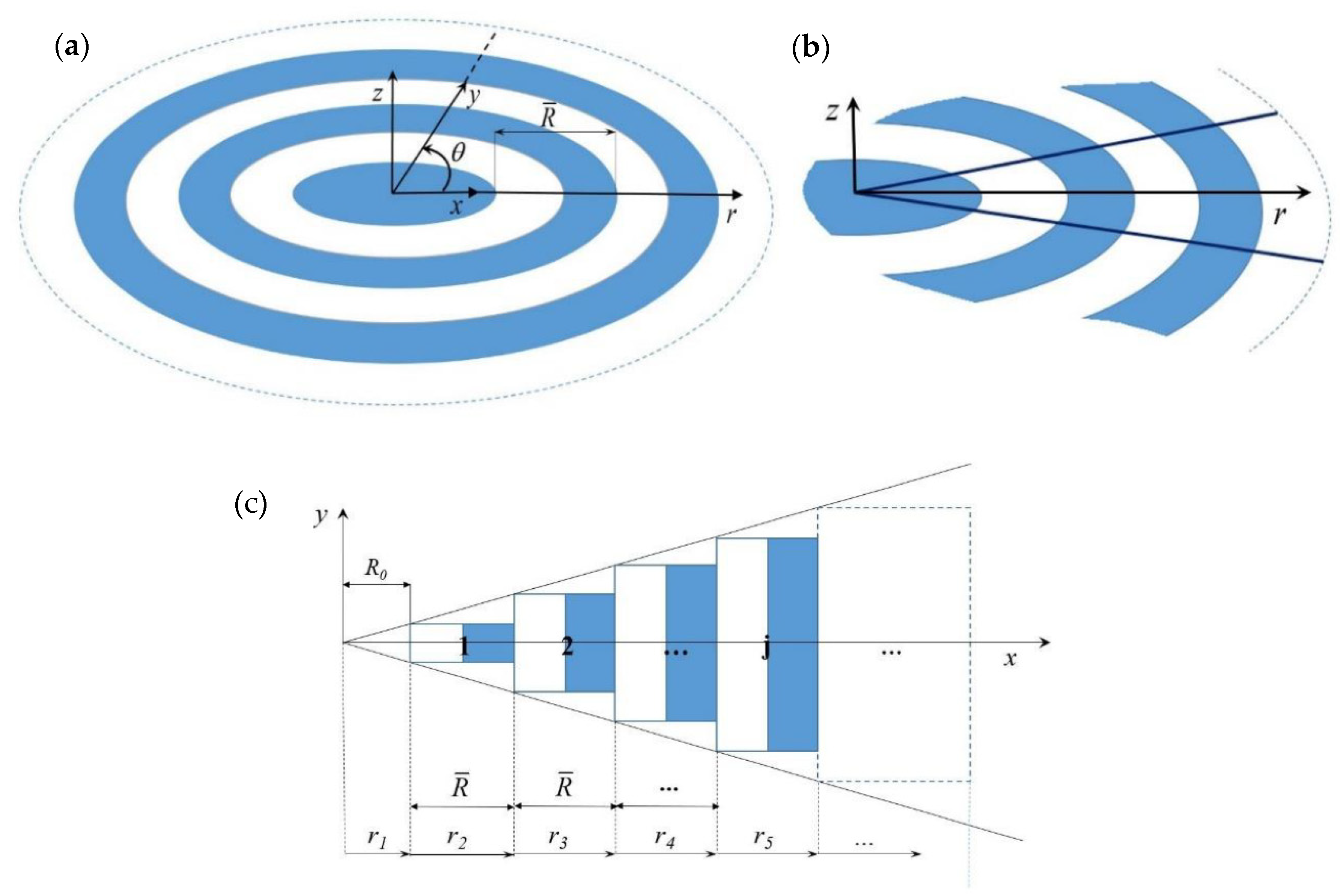
A lossless and linear elastic plate with radial periodicity is considered. The plate consists of an infinite repetition of a sequence of annuli of the same width with alternating properties, as shown in
Figure 1a. The lattice constant, or the characteristic length of the unit cell, is here defined in the radial direction and denoted by
.
In order to apply the WFE method, a slice of the plate is taken, as shown in
Figure 1b. Since the periodicity is in the radial direction, the angle of the slice can be arbitrarily small. The slice is approximated as a piecewise rectangular waveguide in Cartesian coordinates, as shown in
Figure 1c. A finite number of segments is assumed. These segments are numbered increasingly in the radial direction from 1 to
n, where
n is the cell distant
from the centre. Wave characteristics of each of these rectangular segments are obtained using the WFE approach as described in
Section 2.1. In the model, the left nodes of the first cell are shifted at an arbitrarily small distance
from the origin of the coordinates; the inner part,
, is uniform and homogenous.
2.1. Free Wave Propagation Characteristics
Wave characteristics of each segment (cell) in
Figure 1c are evaluated using the WFE method as described in [
14,
28]. The waves are numerically represented by the dispersion curves,
, which give the information about the wave vector
available for each frequency
, and the corresponding FE nodal displacements
and nodal forces
, which occur under the passage of a wave. In the WFE, only the unit periodic cell is analysed.
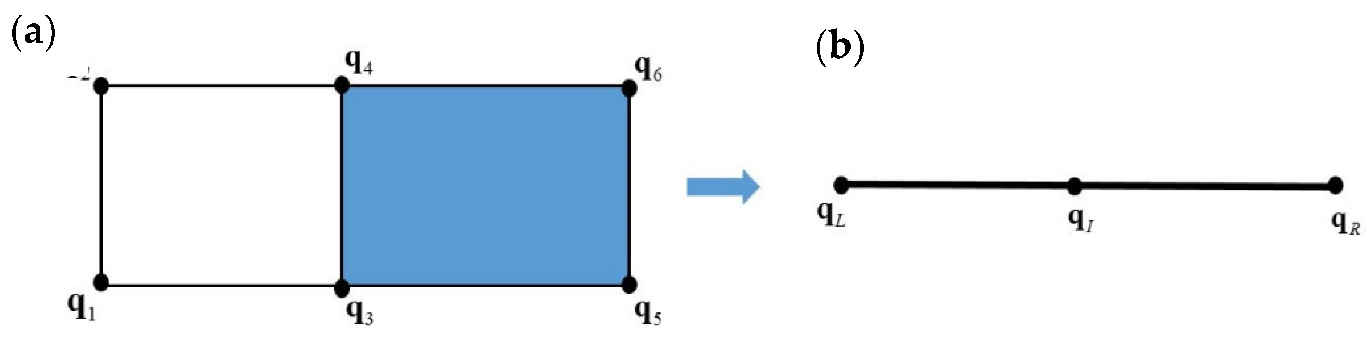
Figure 2 shows a finite element mesh of a unit cell using 4-noded rectangular elements and the correspondent WFE model. The degrees of freedom
in the dicrestised equation of motion, Equation (1), are ordered and condensed as
, where the subscripts
L, R and
I are associated with the right
, left
and interior
nodal degrees of freedom of the cell, with a similar expression for the nodal forces
.
The discretised equation of motion,
, is obtained using conventional FEA and it is partitioned as
To apply the WFE method, the internal Dofs of the unit cell must be reduced. In this paper, a standard dynamic condensation is applied as
However, according to the size of the model, more efficient methods for condensing the inner DOFs and speeding up the resolution of the WFE eigenvalue problem can be applied, e.g., [
35,
36].
The resulting equation of motion is
The inclusion of stress, temperature effects and damping in the model can be accommodated, if necessary, as described in [
37]. Periodicity conditions are applied so that
where
and
is the wavenumber. Combining Equation (4) with Equation (3), the equation of free wave motion takes the form of a quadratic eigenvalue problem, as
whose solutions yield the relationship between the wavenumber and frequency (dispersion curves) and the displacement
of the cross-section due to wave motion (wave mode shapes). Equation (5) can be further recast as a standard linear eigenvalue problem as
,
where , , , and .
The time average energy flow in each segment can be then obtained from
where the superscript
H denotes the Hermitian transpose and
f and
q are recovered using Equations (3) and (4).
2.2. Forced Wave Amplitude
Forced wave propagation and structural response are evaluated following the theory presented in [
27,
28]. Wave properties are grouped into positive and negative going waves, which can be described by the two sets of results
and
. Here
and
are wavenumbers and waves’ amplitudes travelling in the positive and negative direction, while
and
are the corresponding nodal displacements and nodal forces, that is the FE discretisation of wavemodes. For evaluating the forced response, it is advantageous to obtain also the left eigenvectors of the WFE eigenvalue problem in Equation (5). These are partitioned in the same manner as the wavemodes, that is
and
. Left and right eigenvectors are orthogonal and they can be normalised so that
In an analogous manner to the modal analysis, the total displacement and force at the junction of a cell is described by the sum of the positive and negative wavemodes so that
Equation (8) defines the transformation between the physical domain, where the motion is described in terms of nodal displacements and forces, and the wave domain, where the motion is described in terms of waves of amplitudes
travelling in the positive and negative directions. A point force
will generate excited positive and negative going waves, propagating away from the excitation point. Compared to the Cartesian periodicity, in the case of a radially periodic plate, the position of this point force is an independent parameter. Here, we assume a transverse harmonic point force exciting the structure at the left nodes of the first cell in
Figure 1c. With reference to
Figure 1, continuity and equilibrium equations can be written at the left side of the first cell, and excited wave amplitudes can be recovered from Equation (9)
In practice, as in modal analysis, only
m pairs of (positive- and negative-going) waves are retained (a reduced wave basis is assumed in most cases). Moreover, the number of assumed modes can be different at each frequency. It is noteworthy to mention that all the waves propagating in the structure (real wavenumbers) should be considered. Evanescent and attenuating waves (corresponding to pure imaginary or complex wavenumbers) should be also assumed since they play an important role in scattering and forcing problems. Consequently, the wavemodes’ matrix is typically rectangular and the use of standard pseudoinverse operation can lead to numerical errors. To overcome this issue, the orthogonality between right and left eigenvectors in Equation (7) can be exploited, and the excited wave amplitudes at
can be obtained from
2.3. Coupling of the Segments and Wave Amplitude Decay
Compared to the corresponding Cartesian waveguides, wave propagation is not translational invariant in the radially periodic structures, and amplitude attenuation occurs as the waves travel from the centre in the radial direction. Since the energy flowing along the slice is constant, wave amplitude change due to changes in the geometry can be accommodated in the model according to an energy balance principle as in [
31]. In this section, the procedure is presented for the first two cells. The same passages must be applied up to the cell
, including the point at which the response must be evaluated.
In the Cartesian cell, amplitudes are related at two points
and
, by
and
, where
and
. Therefore, nodal displacements and nodal forces at the interface between cell 1 and cell 2 are
Using the left eigenvectors as in Equation (10), the first attempt to find the excited wave amplitude in cell 2 gives
Nodal displacements and nodal forces at cell 2 can be obtained using the same expression of Equation (10)
and the time-averaged energy flows, Equation (6), of cell 1 and cell 2 can be evaluated using nodal displacement and nodal forces from Equations (11) and (13)
The ratio between
and
gives the amplitude decay
in waveguide 2, which is evaluated as in [
32]
The wave and amplitudes in waveguide 2 are therefore approximated to
Equations (13)–(16) can be repeated iteratively until converges to one, and the final value of the wave amplitudes reach the required approximation. One passage was sufficient to converge to a useful approximation with a very low computational cost in the numerical cases studied. Excited wave amplitudes decay in the next cells up to cell n are evaluated following the same passages.
3. Numerical Examples
This section shows two numerical examples: the first concerns a thin isotropic plate excited by a central transverse harmonic force, while the second deals with a plate with a periodic radial change of thickness. In both cases, the WFE model is obtained using 4-noded plane elements in bending having three degrees of freedom per node: translation in the z-direction and rotations around the x- and y-directions. To verify the results, analytical solutions were compared in the first case, while results for the radially periodic plate were verified through comparison with those obtained by an FE model with PMLs. This model was realised in COMSOL Mutiphysics® using the Structural Mechanics Module. The plate was discretised by shell elements having six degrees of freedom per node (translations and rotations in the z, x, and y directions), while a second-order polynomial stretching function was chosen for the PMLs, see the COMSOL Multiphysics Reference Manual for further information. The FE models were realised both in Cartesian and Polar coordinates systems with similar results, and a convergence test was performed by refining the mesh in the PML domain.
The non-dimensional frequency
is introduced, where
,
h and
D are respectively the density, thickness and bending stiffness of the plate,
is the frequency in radiant, and
is the period of the structure as in
Figure 1.
3.1. Numerical Verification. Infinite Plate Subjected to a Transverse Harmonic Force
The literature has largely studied the problem of a thin plate subjected to harmonic loads, and closed-form solutions can be found in many classical books on vibrations, e.g., [
34]. This numerical example is introduced here to verify the method described in
Section 2 and show its applicability to continuous structures.
An aluminium plate of thickness h = 1 mm is considered. Flexural waves in the plate are excited by a central transverse harmonic force of magnitude , and the complex out of plane displacement is evaluated at a distance from the plate centre, viz. origin of the polar coordinates.
In this case, the structure is continuous and uniform, and it can be studied as a periodic structure with arbitrary radial and circumferential periodicity: the choice of the period, viz. length
of the unit cell, is arbitrary under standard FE assumptions to avoid element distortion and dispersion errors [
38]. Therefore, the number of segments that are used to approximate the slice from the centre to
is arbitrarily chosen. The discretisation must be refined until it does not produce a negligible change in the solution. In this example, only three segments have been found sufficient for convergence.
In order to simplify the WFE model, a small circle around the point force is removed and the left nodes of the first cell are shifted at a distance from the point force. In this example, the WFE approximation is obtained for a slice of angle θ = 6o. Waves are induced only in the positive radial direction and therefore is assumed. Periodicity in each segment is further exploited. Here, the number of “sub-period” in each segment is chosen by a simple algorithm that optimises the mesh according to the slice’s dimension and the number of segments. No significant differences are noticed decreasing the distance further.
Figure 3 shows the absolute value and the phase of the transverse displacement of the plate. A comparison between the numerical and analytical solutions is shown. The latter is evaluated using the analytical equation given in [
34]:
, where
is the flexural wavenumber,
is the zero-order Hankel function of the second kind and
is the zero-order modified Bessel function of the second kind.
Results obtained using the FE model of the plate with PMLs are, as seen in
Figure 3, in excellent agreement with the WFE results (small discrepancies are due to the differences in the FE models). However, this numerical study also demonstrates the computational superiority of the WFE method over the standard FE + PML analysis: the CPU time used by Matlab
® to solve the WFE model of the plate was approximately four hundred times less than the CPU time used by COMSOL Mutiphysics
® to solve the correspondent FE + PML model. One of the main reasons for such a difference in the computational cost is the very small size of the WFE matrices compared to the number of DOFs involved in standard FE analysis. The WFE model for this numerical example was realised using one shell element, resulting in 6 DOFs after the WFE reduction, Equation (5), while the size of the FE + PML model was 676,422 DOFs.
3.2. Radially Periodic Plate
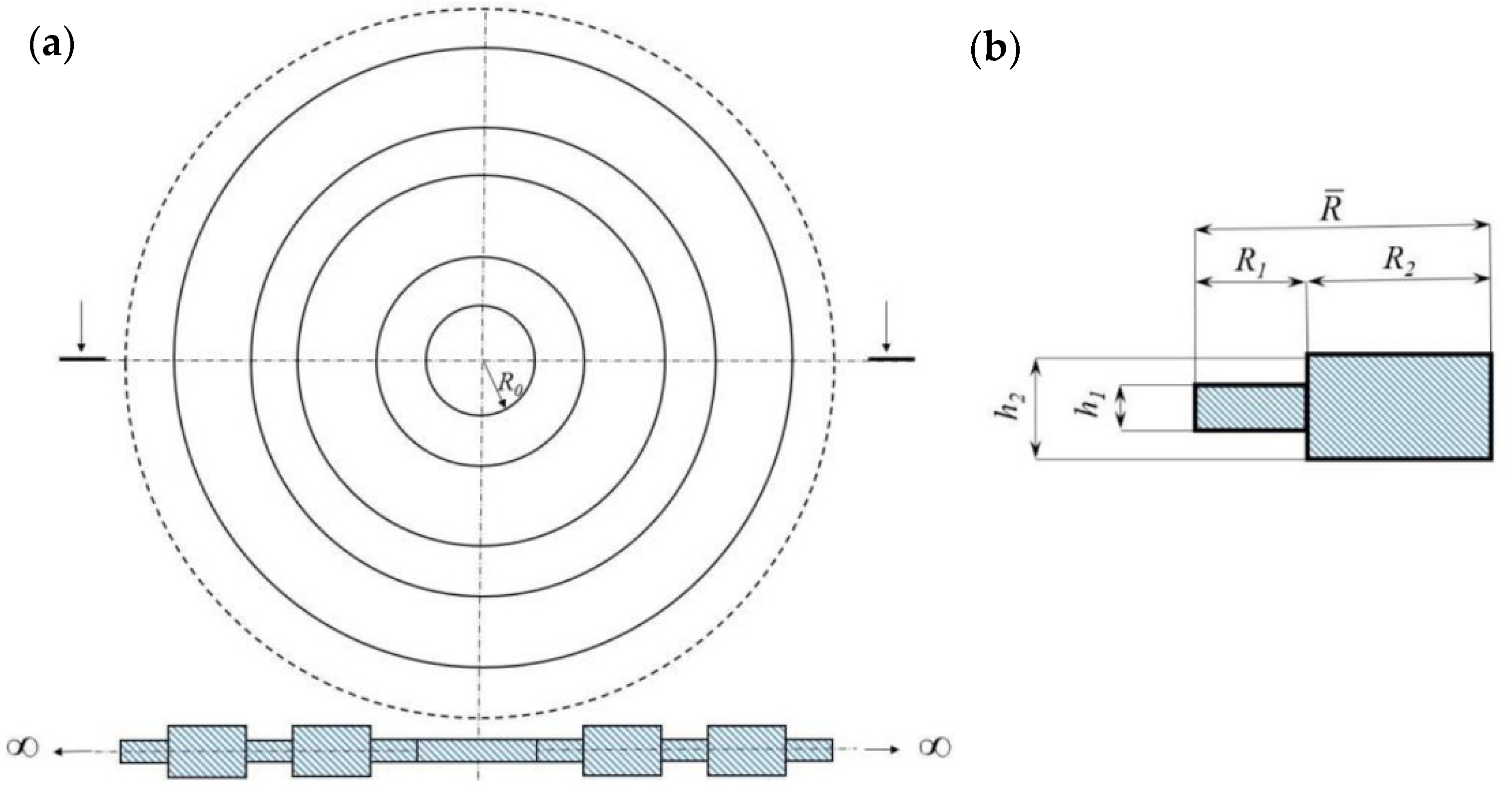
In this section, we consider a plate in polar coordinates with radial periodicity.
Figure 4 depicts a schematic figure of the plate and its unit cell (period). In the following, the characteristic length
and the thickness
h1 are used to define the dimensionless parameters:
The WFE model is obtained considering an arbitrary circumferential periodicity of angle
θ = 9
o. The external harmonic force of magnitude
140 N/m is applied at the internal edge of the plate and included in the WFE by two equivalent transverse nodal forces exciting the left nodes of the first unit cell. Waves are induced only in the positive radial direction and therefore
is assumed. The structure exhibits stop-bands due to its periodicity as shown in [
26]. These stop-bands can be predicted with accuracy by the WFE up to high frequency. However, in this paper, the plate response is evaluated in the nearfield and at a low-frequency. Therefore, only the wave modes below the first stop-band are considered in the analysis.
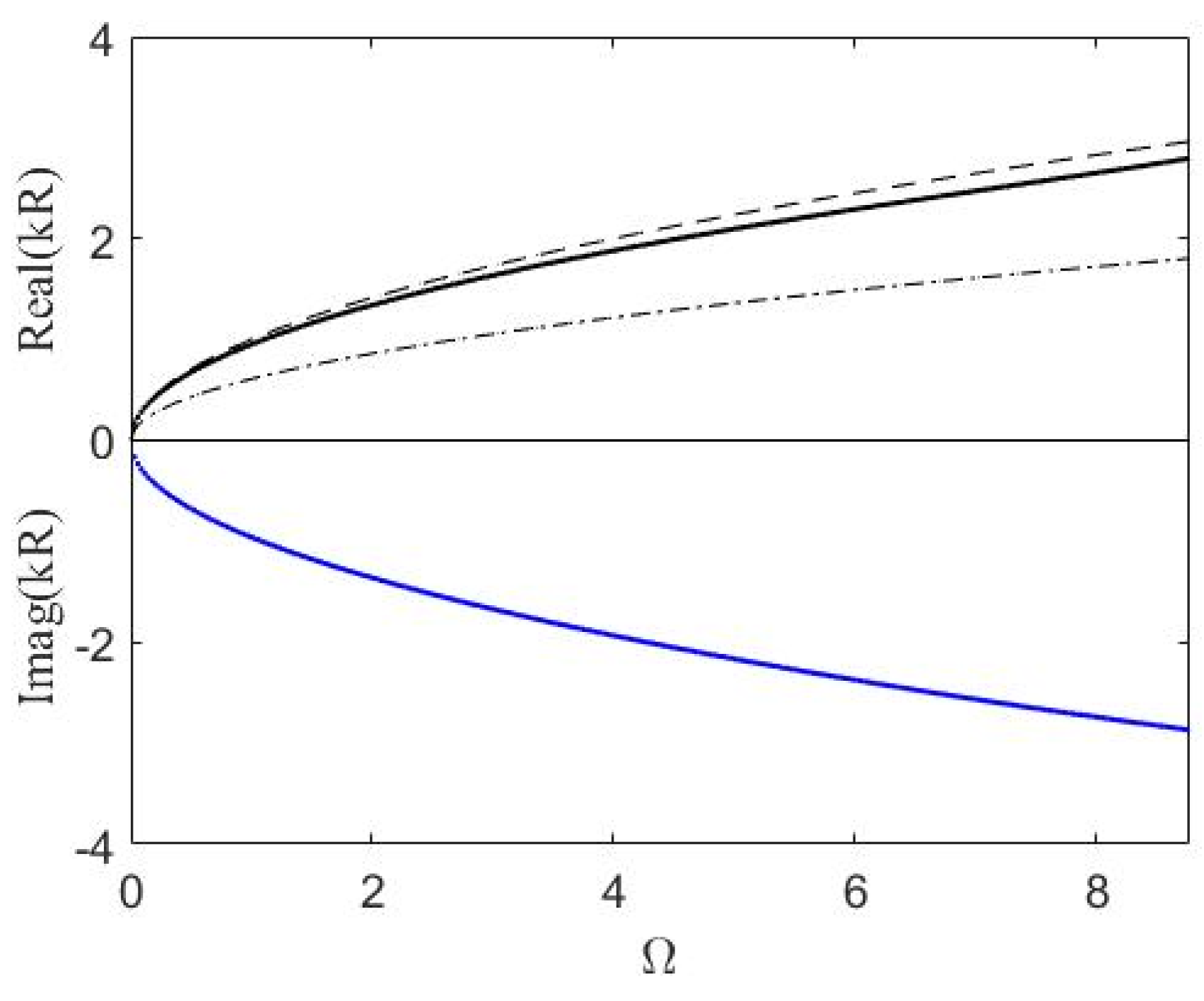
Figure 5 shows the dispersion curves of flexural waves propagating in the positive direction. Analytical flexural waves propagating in the corresponding homogeneous plates of thickness
h1 and
h2 are also shown for comparison.
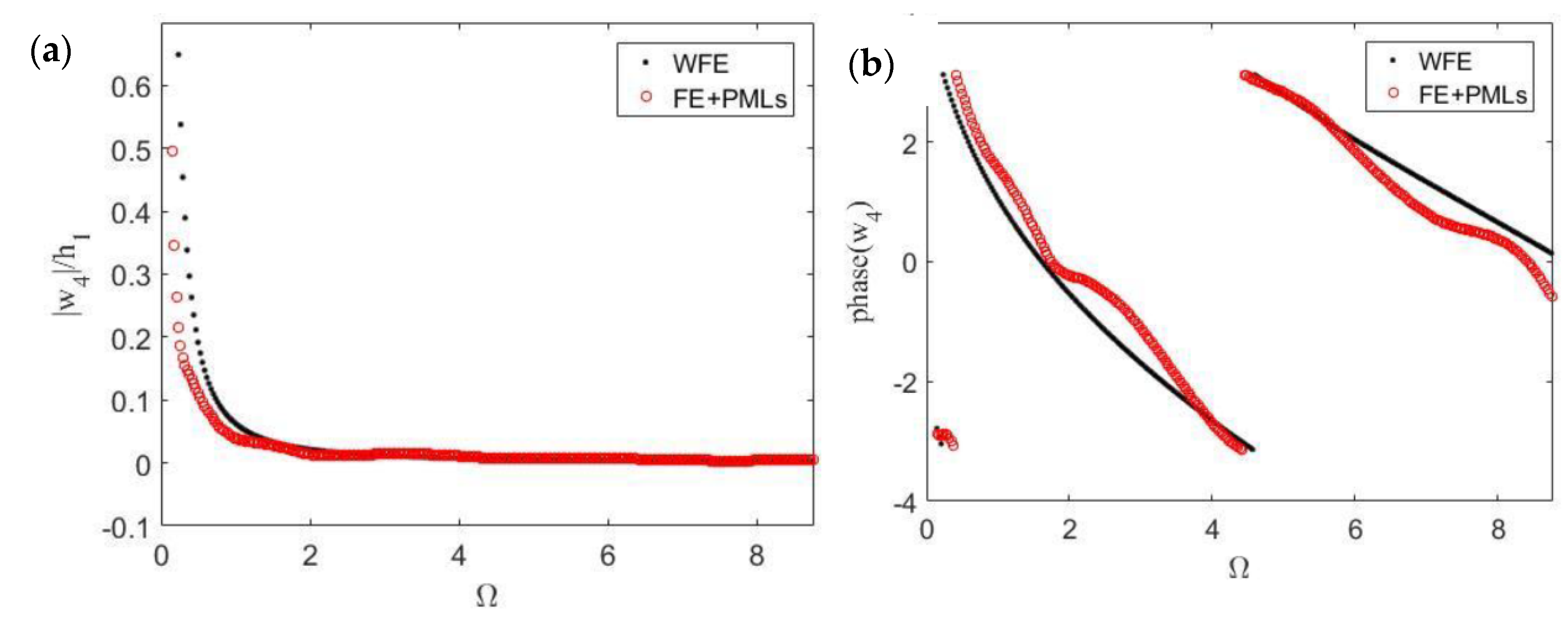
The transverse response of the plate is evaluated after 4 unit cells, at a distance
from the centre of the plate (or equally at a distance
from the border of the internal hole).
Figure 6 shows the displacements in terms of absolute and phase values. Results obtained using the FE model with PMLs are also presented. Although some small discrepancies were expected due to the very different FE discretisation and a very different approach to the problem, it can be noticed that the results obtained by the WFE method are in good agreement with those obtained by the finite element harmonic analysis. The WFE model for each segment of the plate slice was set up with three shell elements, resulting in six DOFs after the WFE reduction, while the FE + PML had 794,448 DOFs. The computational time used by Matlab
® to solve the WFE model of this radially periodic plate was almost two thousand times less than the CPU time used by COMSOL Mutiphysics
® to solve the correspondent FE + PML model.


