
Analytical Model to Calculate Radial Forces in Permanent-Magnet Synchronous Machines


Abstract
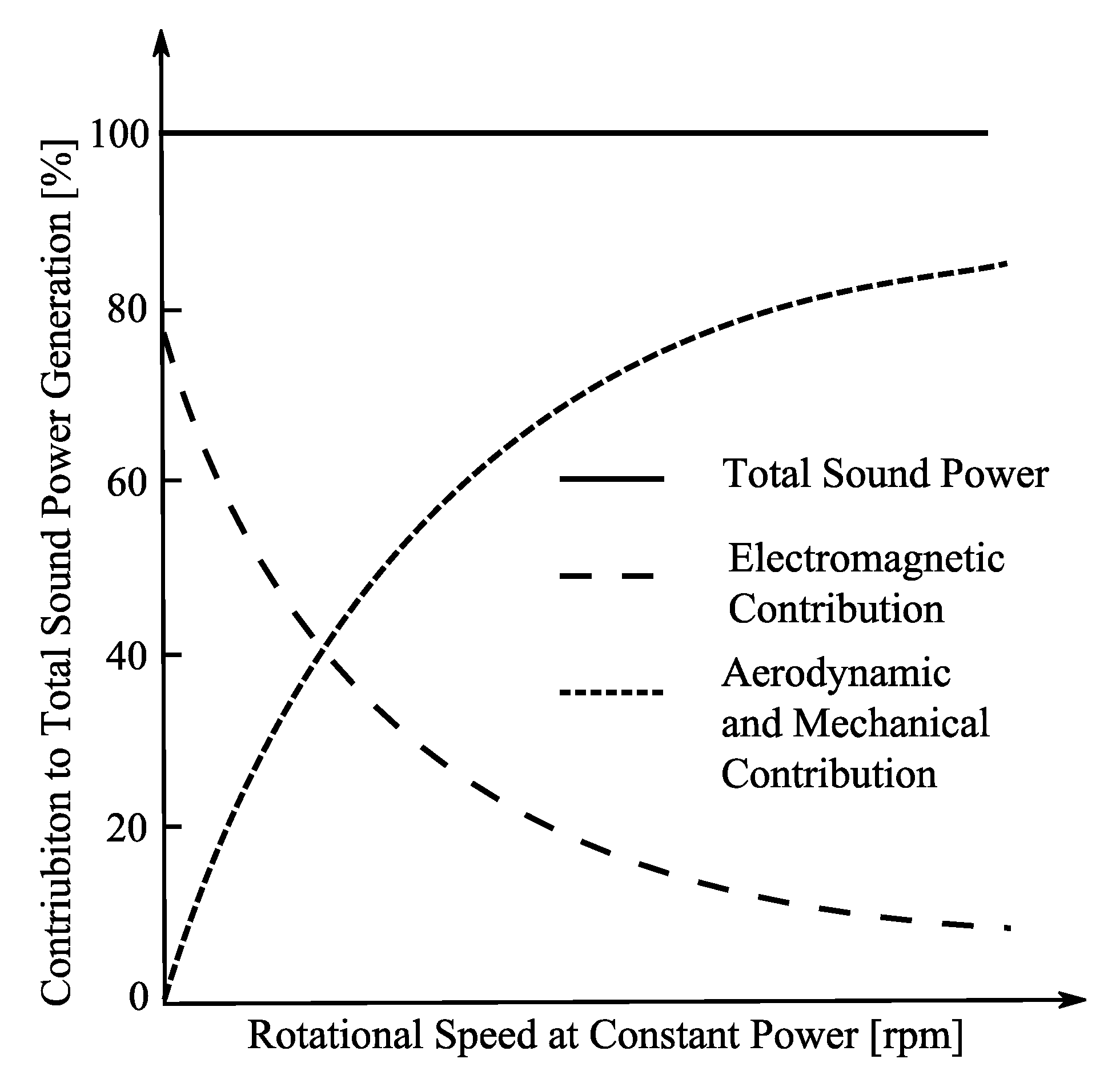
:1. Introduction
- electromagnetic sources,
- mechanical sources,
- aerodynamic sources.
2. Sources of Magnetic Forces in PMSMs
2.1. Magnetic Pressures on the Stator
2.2. Magnetic Pressures on the Rotor
2.2.1. Oscillating Magnetic Pressure Due to the Stator Slots
2.2.2. Oscillating Magnetic Pressure Created by the Stator Winding
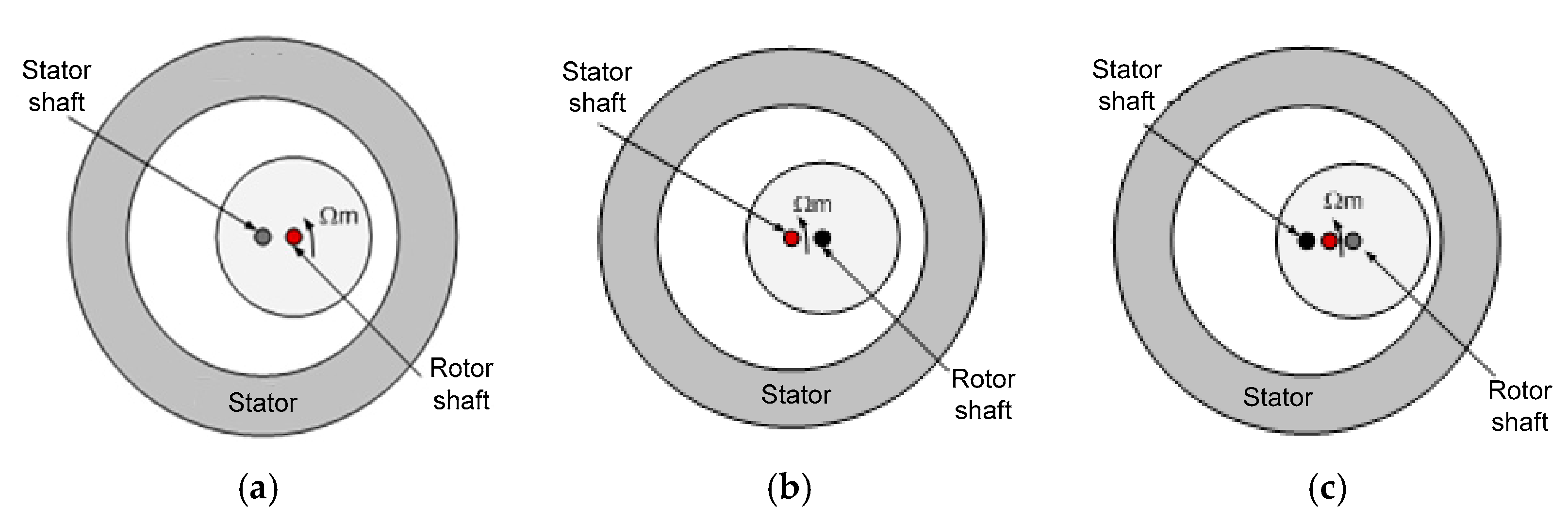
2.3. Magnetic Forces Due to Eccentricities
3. Analytical Model
3.1. Complex Fourier Series
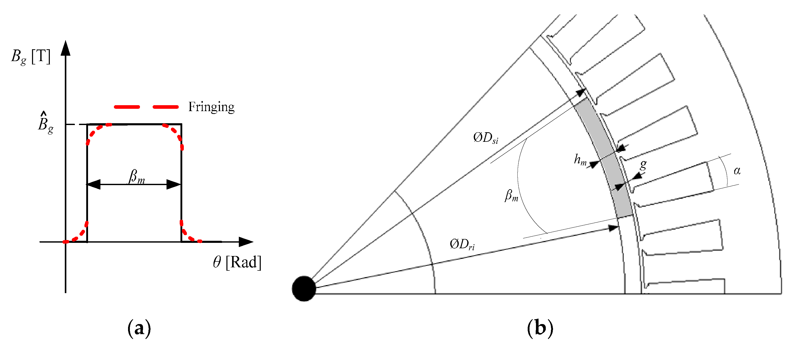
3.2. Magnetic Flux Density Created by Magnets in a Slotless Machine
3.3. Magnetic Flux Density Created by Coils in a Slotless Machine
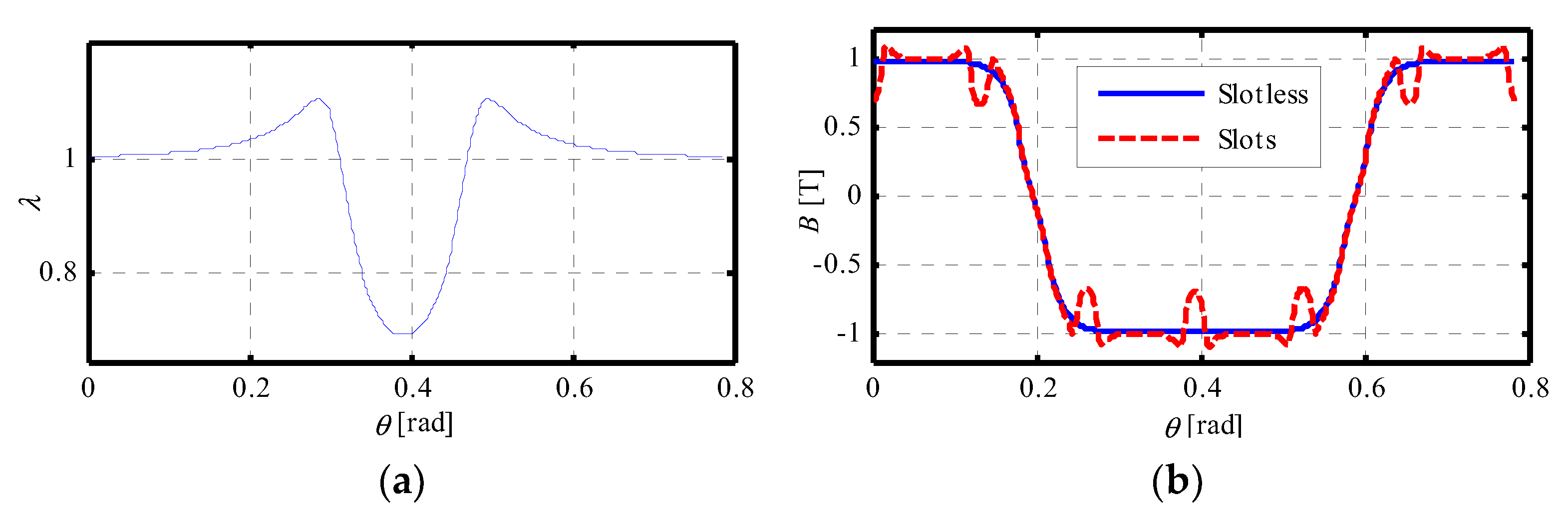
3.4. Effect of the Stator Slots
3.5. Computation of the Magnetic Forces on the Stator
4. Validation
4.1. Analytical Results vs. FEM Results
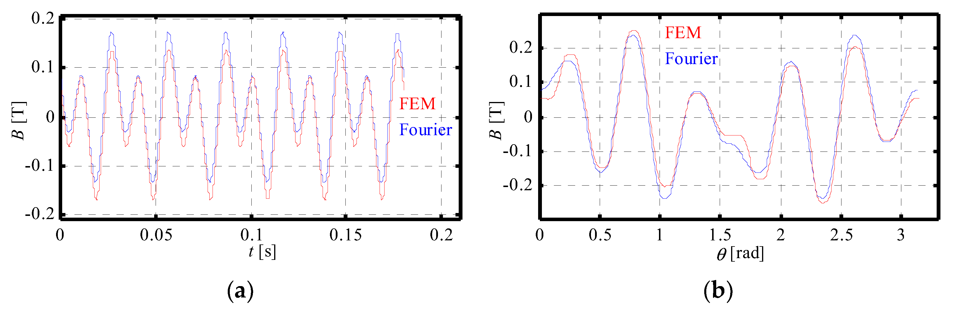
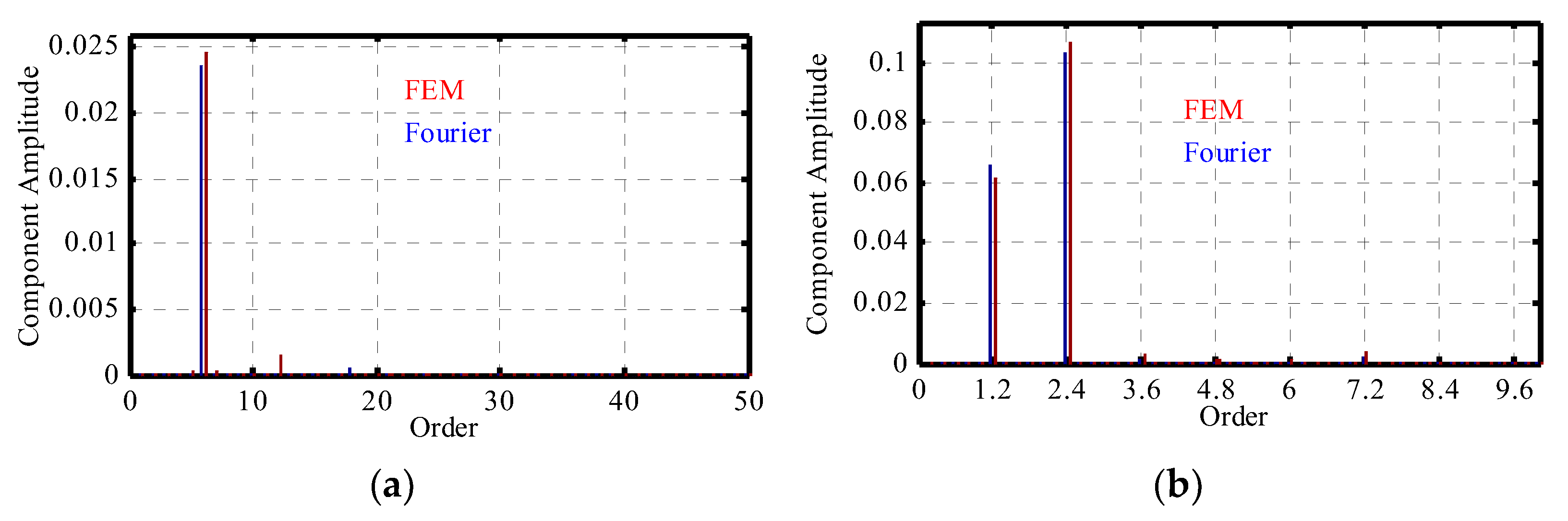
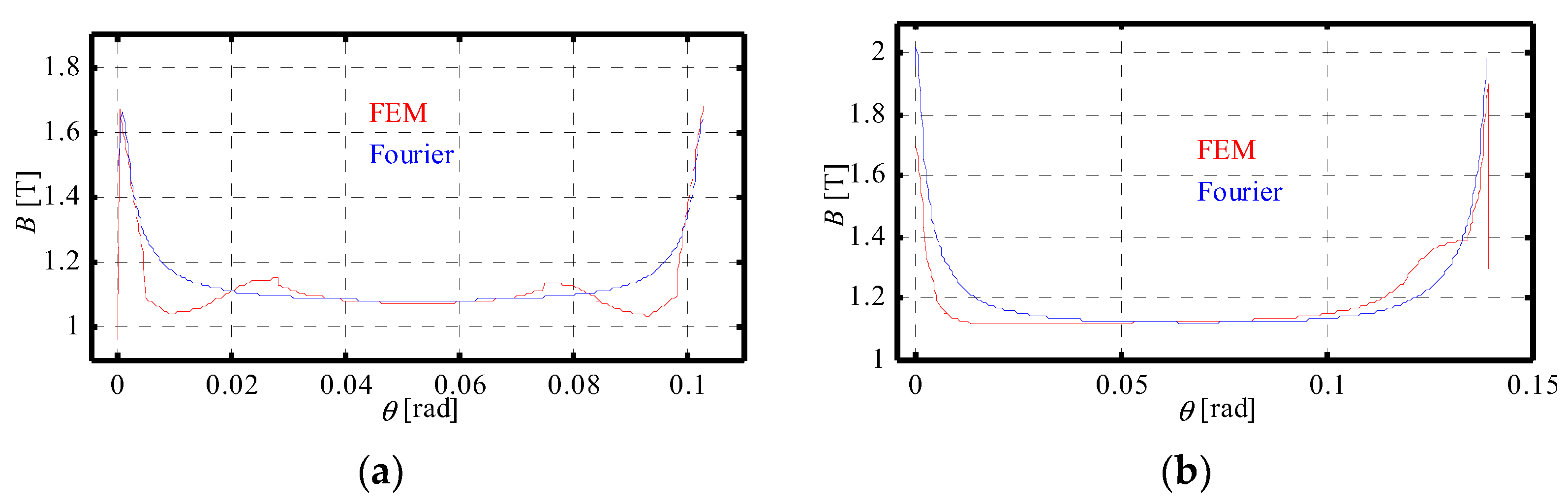
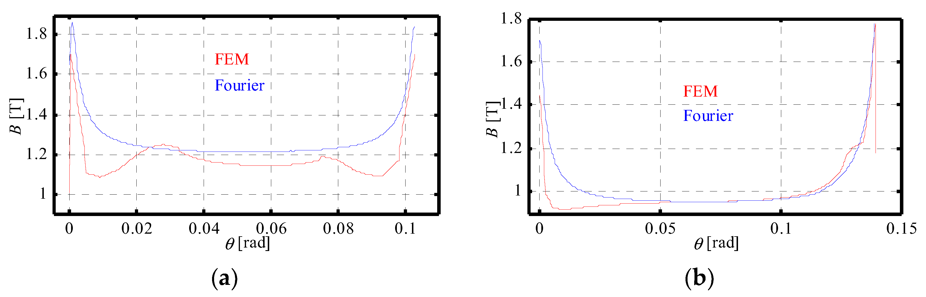
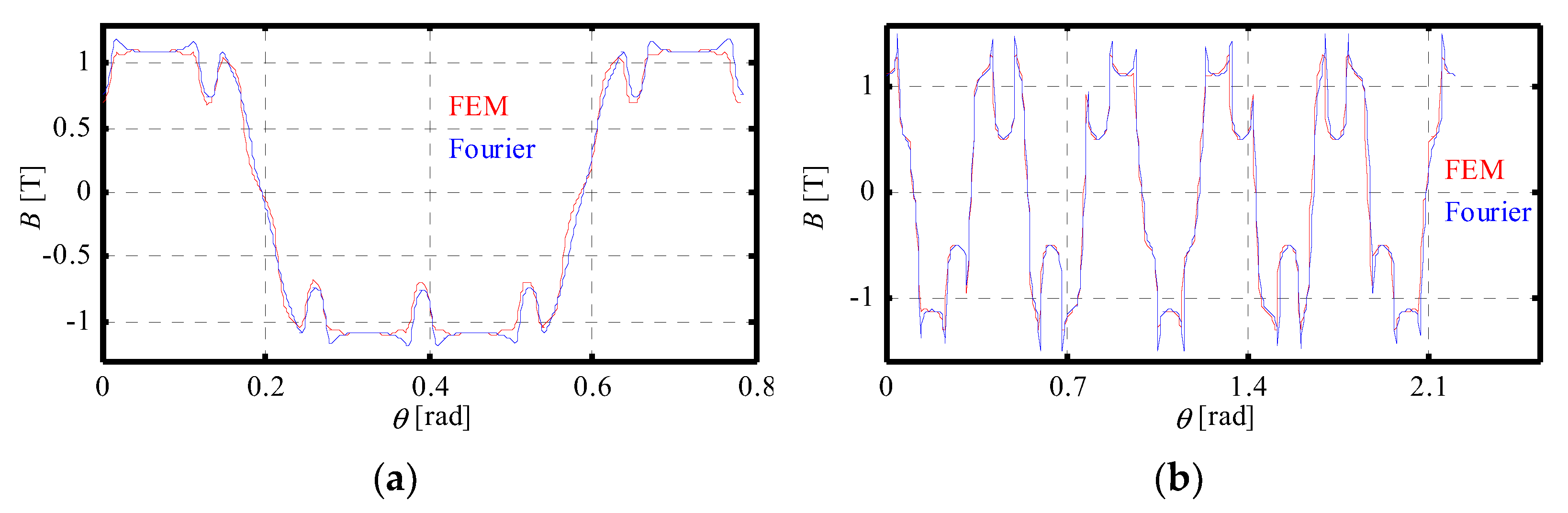
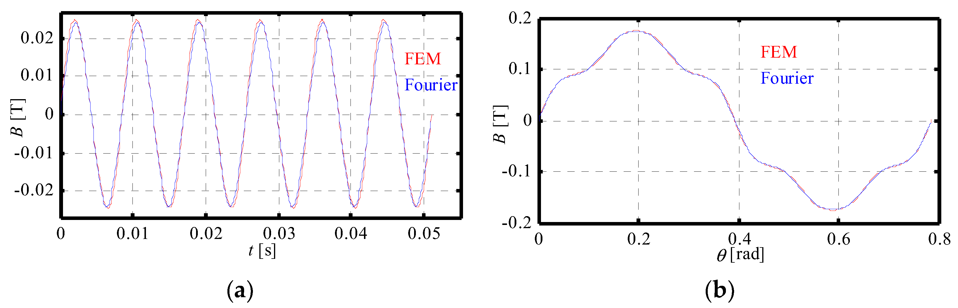
4.1.1. Magnetic Flux Densities
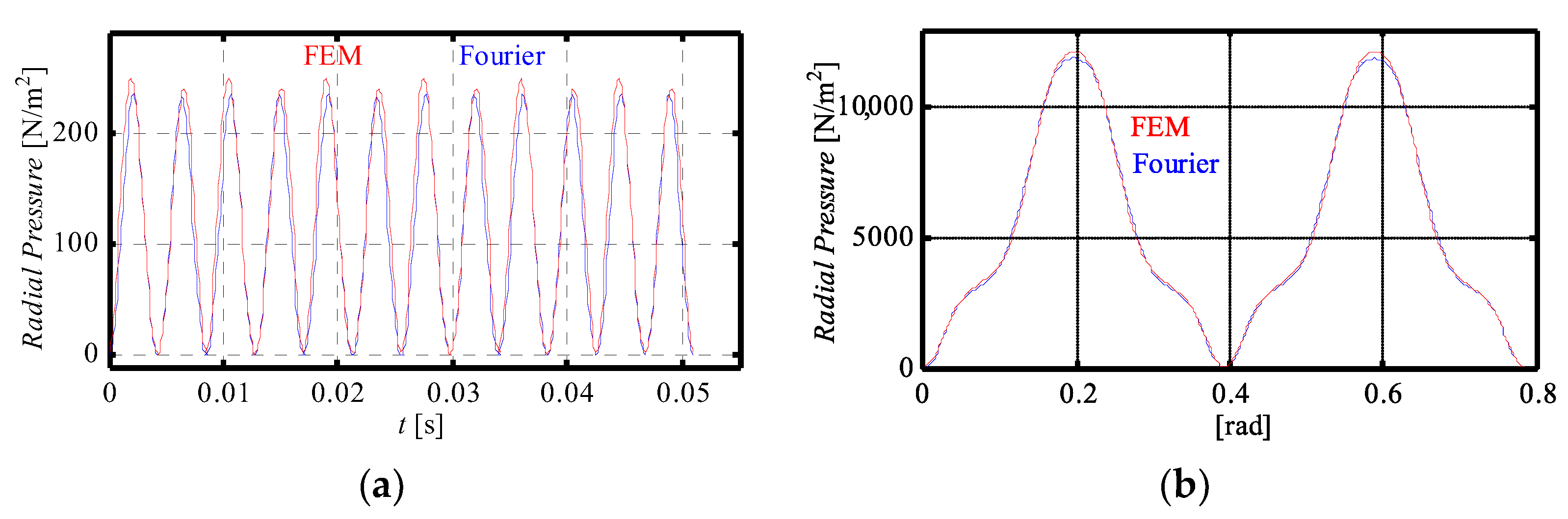
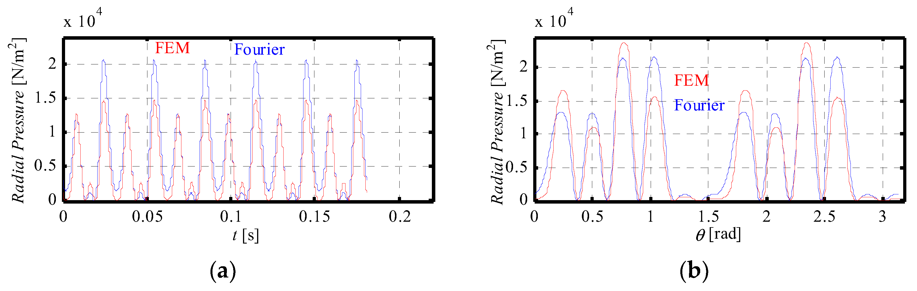
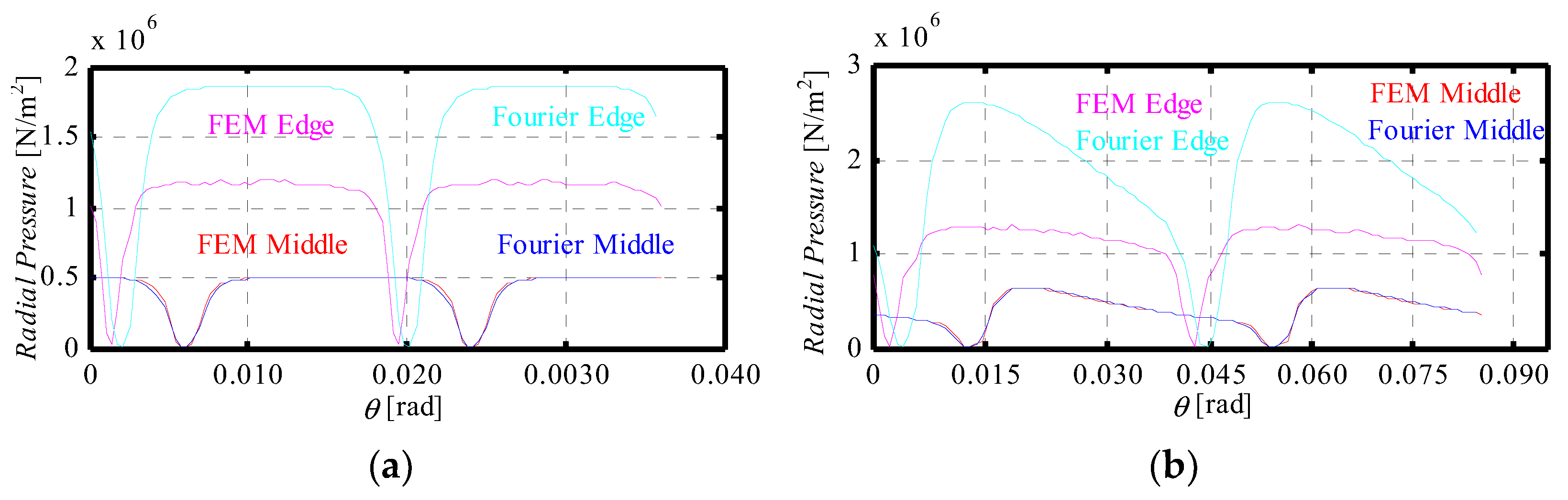
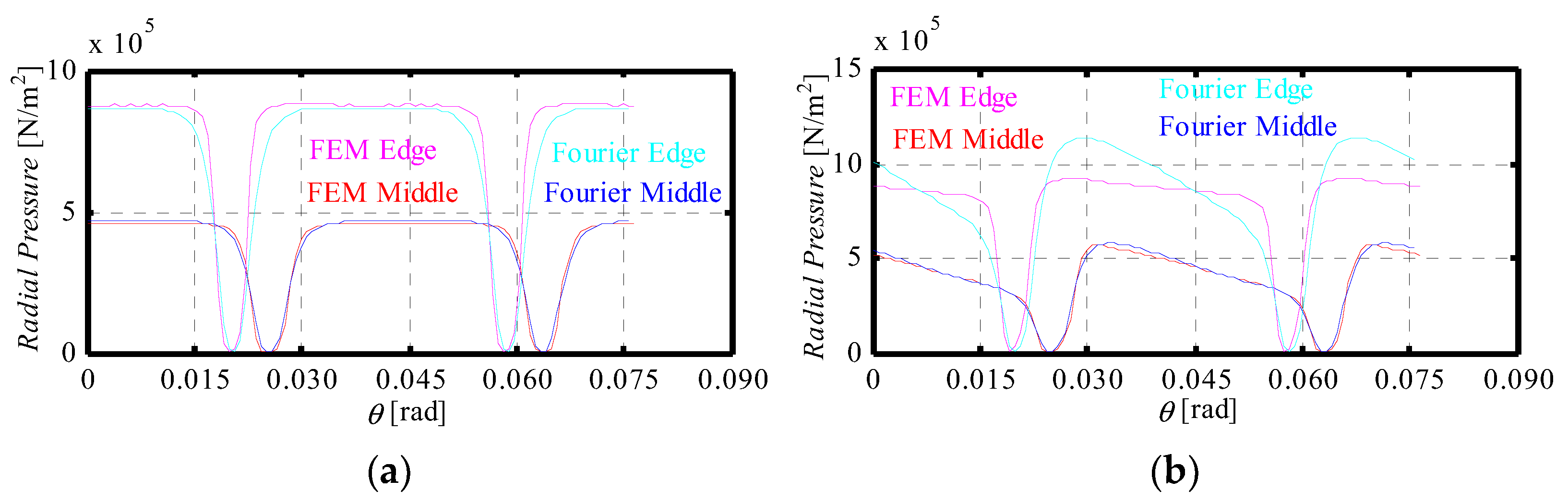
4.1.2. Magnetic Pressure
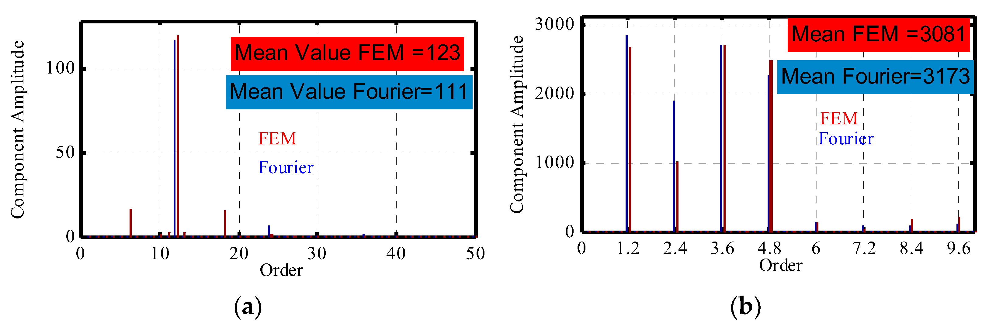
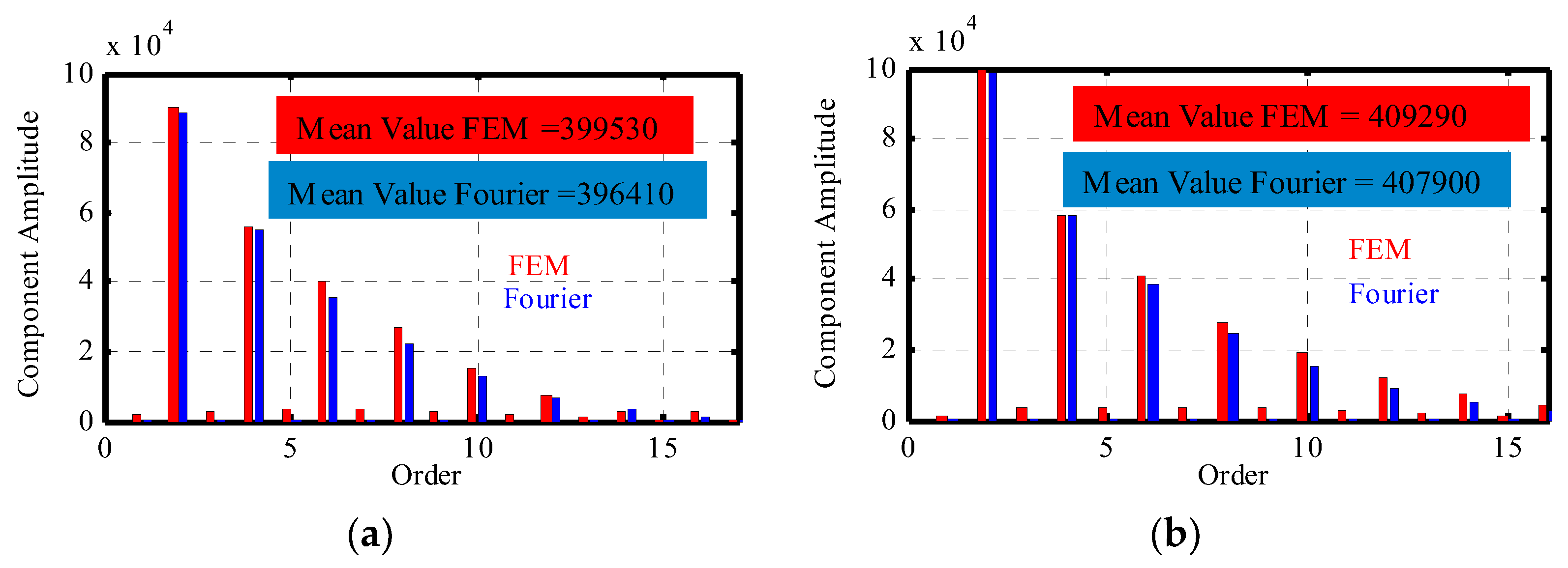
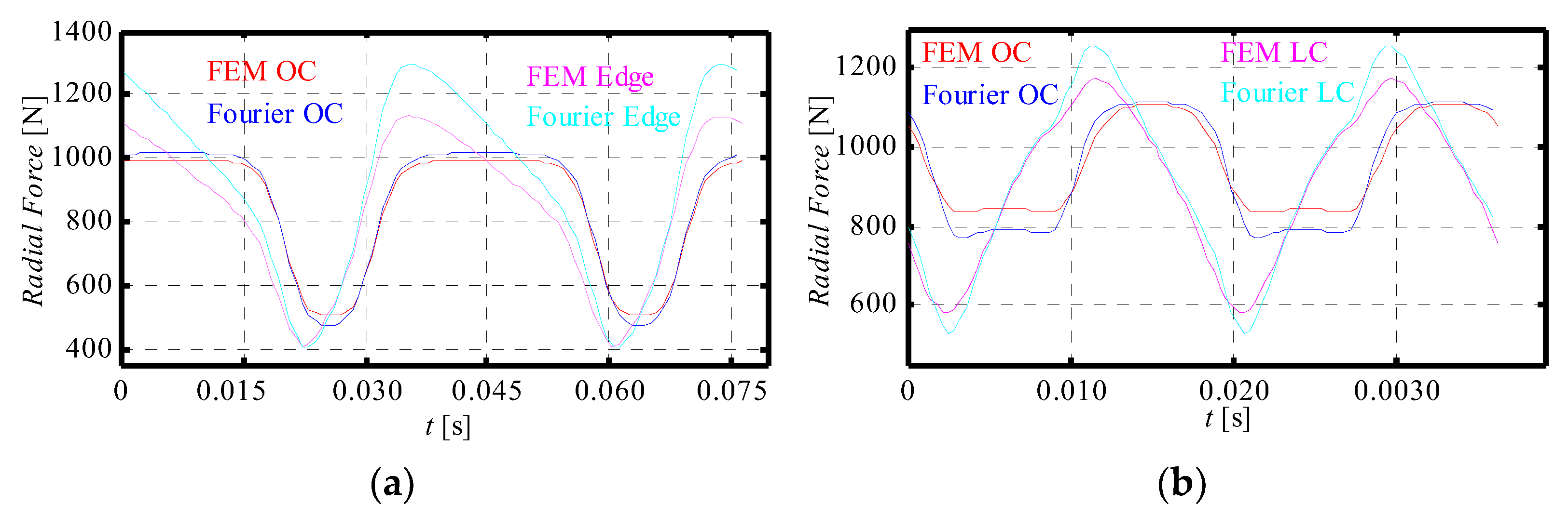
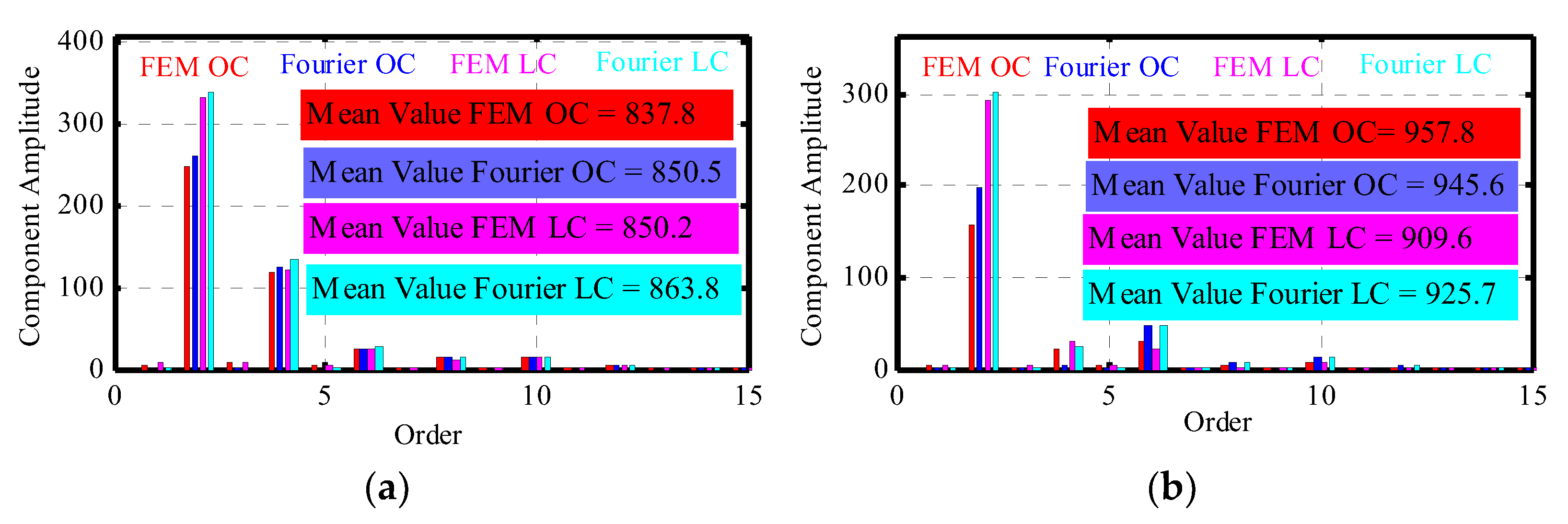
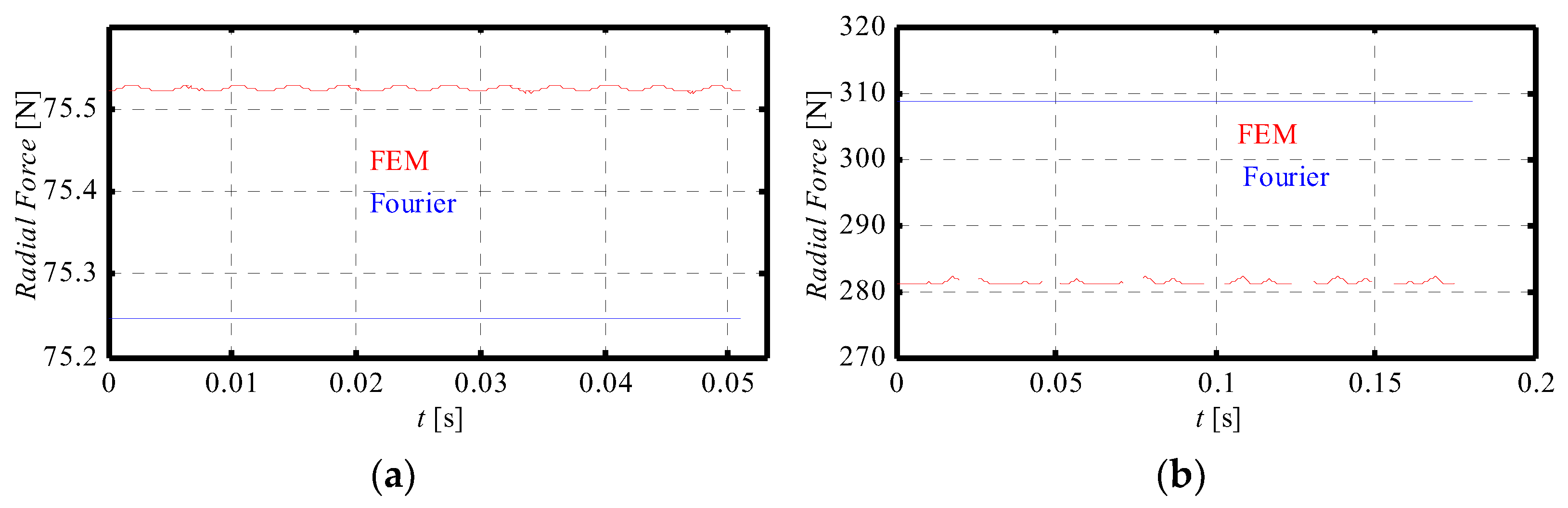
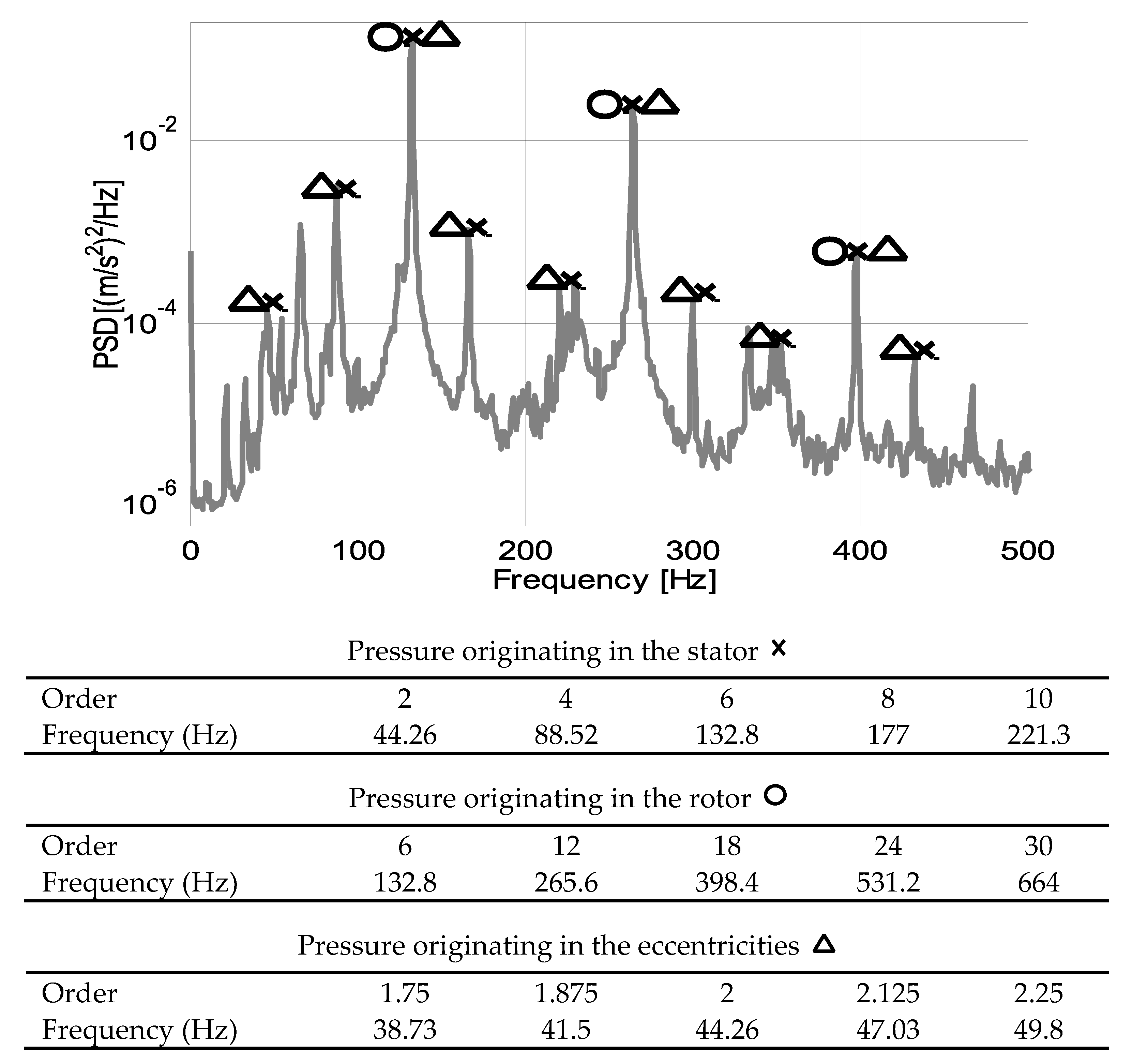
4.1.3. Magnetic Forces
4.2. Experimental Validation
5. Conclusions
Author Contributions
Funding
Conflicts of Interest
References
- Gieras, J.F.; Chong, W.; Lai, J.C. Noise of Polyphase Electric Motors; Taylor & Francis: Boca Raton, FL, USA, 2006. [Google Scholar]
- Gómez, A.M. Predicción del Comportamiento Vibratorio y Acústico de una Máquina Eléctrica; Mondragon Goi Eskola Politeknikoa: Mondragón, Spain, 2013; pp. 1–92. [Google Scholar]
- Sun, T.; Kim, J.-M.; Lee, G.-H.; Hong, J.-P.; Choi, M.-R. Effect of Pole and Slot Combination on Noise and Vibration in Permanent Magnet Synchronous Motor. IEEE Trans. Magn. 2011, 47, 1038–1041. [Google Scholar] [CrossRef]
- Islam, R.; Husain, I. Analytical Model for Predicting Noise and Vibration in Permanent-Magnet Synchronous Motors. IEEE Trans. Ind. Appl. 2010, 46, 2346–2354. [Google Scholar] [CrossRef]
- He, G.; Huang, Z.; Qin, R.; Chen, D. Numerical Prediction of Electromagnetic Vibration and Noise of Permanent-Magnet Direct Current Commutator Motors With Rotor Eccentricities and Glue Effects. IEEE Trans. Magn. 2012, 48, 1924–1931. [Google Scholar] [CrossRef]
- Mai, H.C.M.; Bernard, R.; Bigot, P.; Dubas, F.; Chamagne, D.; Espanet, C. Consideration of Radial Magnetic Forces in Brushless DC Motors. In Proceedings of the 2010 International Conference on Electrical Machines and Systems, Incheon, Korea, 10–13 October 2010. [Google Scholar]
- Kim, D.C.K. Modelling of Electromagnetic Excitation Forces of Small Induction Motor for Vibration and Noise Analysis. Electr. Power Appl. IEEE Proc. 1998, 145, 199–205. [Google Scholar]
- Verma, S.P.; Balan, A. Experimental Investigations on the Stators of Electrical Machines in Relation to Vibration and Noise Problems. Electr. Power Appl. IEEE Proc. 1998, 145, 455–461. [Google Scholar] [CrossRef]
- Barriga, S.Z. Accionamiento de Alto Confort para Aplicaciones de Elevación. Ph.D. Thesis, Mondragon Goi Eskola Politeknikoa, Mondragón, Spain, 2018. [Google Scholar]
- Armentia, S. Diseño de Motores Gearless sin Neodimio para Aplicaciones de Ascensor; Mondragon Goi Eskola Politeknikoa: Mondragón, Spain, 2014; pp. 1–87. [Google Scholar]
- Hwang, C.C.; Chang, S.M.; Pan, C.T.; Chang, T.Y. Estimation of Parameters of Interior Permanent Magnet Synchronous Motors. J. Magn. Magn. Mater. 2002, 239, 600–603. [Google Scholar] [CrossRef]
- Zhu, L.; Jiang, S.Z.; Zhu, Z.Q.; Chan, C.C. Analytical Modeling of Open-Circuit Air-Gap Field Distributions in Multisegment and Multilayer Interior Permanent-Magnet Machines. Magn. IEEE Trans. 2009, 45, 3121–3130. [Google Scholar] [CrossRef] [Green Version]
- Ugalde, G.; Poza, J.; Rodriguez, M.A.; Gonzalez, A. Space harmonic modeling of fractional permanent magnet machines from star of slots. In Proceedings of the 2008 18th International Conference on Electrical Machines, Vilamoura, Portugal, 6–9 September 2008; pp. 1–6. [Google Scholar]
- Almandoz, G.; Poza, J.; Rodriguez, M.A.; Gonzalez, A. Analytic model of a PMSM considering spatial harmonics. In Proceedings of the 2008 International Symposium on Power Electronics, Electrical Drives, Automation and Motion, Ischia, Italy, 11–13 June 2008; pp. 603–608. [Google Scholar]
- Ugalde, G. Study on Concentrated Windings Permanent Magnet Machines for Direct Drive Applications; Mondragon Goi Eskola Politeknikoa: Mondragón, Spain, 2009; pp. 1–229. [Google Scholar]
- Ackermann, B.; Sottek, R.; Janssen, J.H.H.; van Steen, R.I. New Technique for Reducing Cogging Torque in a Class of Brushless DC Motors. Electr. Power Appl. IEEE Proc. B 1992, 139, 315–320. [Google Scholar] [CrossRef]
- Egea, A.; Almandoz, G.; Poza, J.; Gonzalez, A. Analytic model of axial flux permanent magnet machines considering spatial harmonics. In Proceedings of the International Symposium on Power Electronics, Electrical Drives, Automation and Motion (Electronic Resource), Pisa, Italy, 14–16 June 2010; pp. 495–500. [Google Scholar]
- Hendershot, J.R.; Miller, T.J.E. Design of Brushless Permanent-Magnet Machines. Magna Physic Publishing. 2010. Available online: https://www.semanticscholar.org/paper/Design-of-Brushless-Permanent-Magnet-Machines-Hendershot-Miller/a17fe7805b8cb5d0d1cd68409195eb21cade4250 (accessed on 13 November 2021).
- Miller, T.J.E.; Rabinovici, R. Back-EMF Waveforms and Core Losses in Brushless DC Motors. IEEE Proc. Electr. Power Appl. 1994, 141, 144–154. [Google Scholar] [CrossRef]
- Sebastian, T.; Gangla, V. Analysis of Induced EMF Waveforms and Torque Ripple in a Brushless Permanent Magnet Machine. IEEE Trans. Ind. Appl. 1996, 32, 195–200. [Google Scholar] [CrossRef]
- Zhu, Z.Q.; Howe, D.; Bolte, E.; Ackerman, B. Instantaneous Magnetic Field Distribution in Brushless Permanent Magnet DC Motors. I. Open-circuit field. IEEE Trans. Magn. 1993, 29, 124–135. [Google Scholar] [CrossRef]
- Zhu, Z.Q.; Howe, D. Instantaneous Magnetic Field Distribution in Brushless Permanent Magnet DC Motors. II. Armature-Reaction Field. IEEE Trans. Magn. 1993, 29, 136–146. [Google Scholar] [CrossRef]
- Zhu, Z.Q.; Howe, D. Instantaneous Magnetic Field Distribution in Brushless Permanent Magnet DC Motors. III. Effect of Stator Slotting. IEEE Trans. Magn. 1993, 29, 143–151. [Google Scholar] [CrossRef]
- Zhu, Z.Q.; Howe, D. Instantaneous Magnetic Field Distribution in Permanent Magnet Brushless DC Motors, Part IV: Magnetic Field on Load. IEEE Trans. Magn. 1993, 29, 152–158. [Google Scholar] [CrossRef]
- Proca, A.B.; Keyhani, A.; EL-Antably, A.; Lu, W.; Dai, M. Analytical Model for Permanent Magnet Motors with Surface Mounted Magnets. IEEE Trans. Energy Convers. 2003, 18, 386–391. [Google Scholar] [CrossRef]
- Zhu, Z.Q.; Ishak, D.; Howe, D.; Chen, J. An Analytical Model of Unbalanced Magnetic Force in Fractional-Slot Surface-Mounted Permanent Magnet Machines. IEEE Trans. Magn. 2010, 46, 2686–2700. [Google Scholar] [CrossRef]
- Dajaku, G.; Gerling, D. The Influence of Permeance Effect on the Magnetic Radial Forces of Permanent Magnet Synchronous Machines. IEEE Trans. Magn. 2013, 49, 2953–2966. [Google Scholar] [CrossRef]
- Mendizabal, M.; McCloskey, A.; Poza, J.; Zárate, S.; Iriondo, J.; Irazu, L. Optimum Slot and Pole Design for Vibration Reduction in Permanent Magnet Synchronous Motors. Appl. Sci. 2021, 11, 4849. [Google Scholar] [CrossRef]
- Gomez, I.; Almandoz, G.; Poza, J.; Ugalde, G.; Escalada, A.J. Analytical Model to Calculate Radial Forces in Permanent-Magnet Synchronous Machines. In Proceedings of the 2014 International Conference on Electrical Machines (ICEM), Berlin, Germany, 2–5 September 2014; pp. 2681–2687. [Google Scholar]


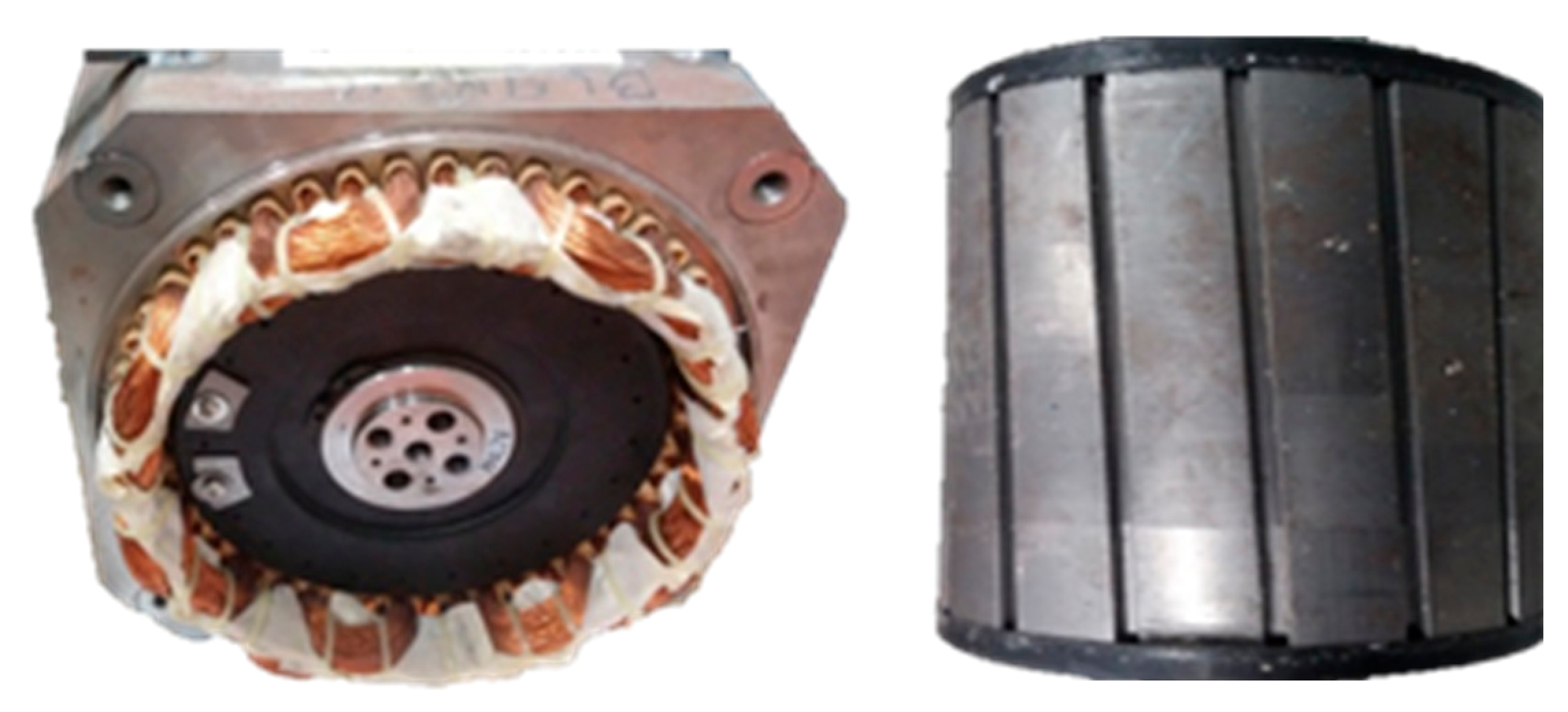
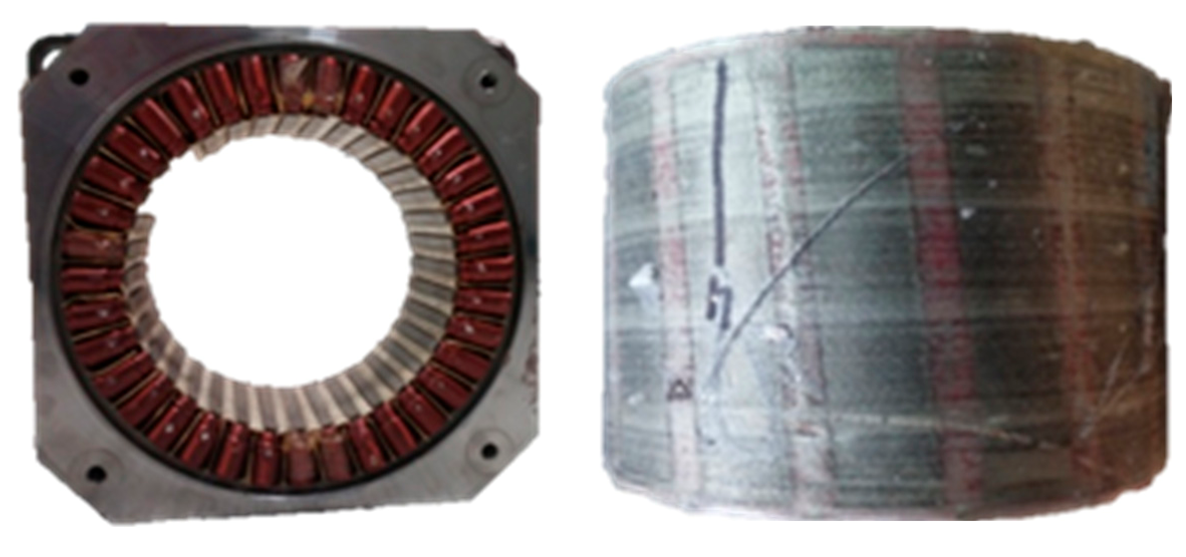
| Machine | Slot Number | Pole Pair Number | Nominal Power | Nominal Speed |
|---|---|---|---|---|
| Q48p8 | 48 | 8 | 4.5 kW | 145 rpm |
| Qs36p15 | 36 | 15 | 4.5 kW | 170 rpm |
| Flux Density Harmonics | Magnetic Pressure Harmonics | Flux Density Harmonics | Magnetic Pressure Harmonics | ||
|---|---|---|---|---|---|
| n | k | µ = ±(n ± k) | n | k | µ = ±(n ± k) |
| ±1 | ±1 | 0 | ±2 | ±5 | ±1 | ±4 | ±6 |
| ±3 | ±2 | ±4 | ±3 | ±2 | ±8 | ||
| ±5 | ±4 | ±6 | ±5 | 0 | ±10 | ||
| ±7 | ±6 | ±8 | ±7 | ±2 | ±12 | ||
| ±9 | ±8 | ±10 | ±9 | ±4 | ±14 | ||
| ±3 | ±1 | ±2 | ±4 | ±7 | ±1 | ±6 | ±8 |
| ±3 | 0 | ±6 | ±3 | ±4 | ±10 | ||
| ±5 | ±2 | ±8 | ±5 | ±2 | ±12 | ||
| ±7 | ±4 | ±10 | ±7 | 0 | ±14 | ||
| ±9 | ±6 | ±12 | ±9 | ±2 | ±16 | ||
| Flux Density Harmonics | Magnetic Pressure Harmonics | Flux Density Harmonics | Magnetic Pressure Harmonics | ||
|---|---|---|---|---|---|
| m | l | µ = ±(m ± l) | m | l | µ = ±(m ± l) |
| ±Qs/p | ±Qs/p | 0 | ±2Qs/p | ±3Qs/p | ±Qs/p | ±2Qs/p | ±4Qs/p |
| ±2Qs/p | ±Qs/p | ±3Qs/p | ±2Qs/p | ±Qs/p | ±5Qs/p | ||
| ±3Qs/p | ±2Qs/p | ±4Qs/p | ±3Qs/p | 0 | ±6Qs/p | ||
| ±4Qs/p | ±3Qs/p | ±5Qs/p | ±4Qs/p | ±Qs/p | ±7Qs/p | ||
| ±5Qs/p | ±4Qs/p | ±6Qs/p | ±5Qs/p | ±2Qs/p | ±8Qs/p | ||
| ±2Qs/p | ±Qs/p | ±Qs/p | ±3Qs/p | ±4Qs/p | ±Qs/p | ±3Qs/p | ±5Qs/p |
| ±2Qs/p | 0 | ±4Qs/p | ±2Qs/p | ±2Qs/p | ±6Qs/p | ||
| ±3Qs/p | ±Qs/p | ±5Qs/p | ±3Qs/p | ±Qs/p | ±7Qs/p | ||
| ±4Qs/p | ±2Qs/p | ±6Qs/p | ±4Qs/p | 0 | ±8Qs/p | ||
| ±5Qs/p | ±3Qs/p | ±7Qs/p | ±5Qs/p | ±Qs/p | ±9Qs/p | ||
| Fixed Reference (Stator) | Moving Reference (Rotor) | |
|---|---|---|
| Order | Sign | Order |
| n = 1 | s = 1 | (s − n) = 0 |
| n = 5 | s = −1 | (s − n) = −6 |
| n = 7 | s = 1 | (s − n) = −6 |
| n = 11 | s = −1 | (s − n) = −12 |
| n = 13 | s = 1 | (s − n) = −12 |
| Fixed Reference (Stator) | Moving Reference (Rotor) | |
|---|---|---|
| Order | Sign | Order |
| n = 1 | s = −1 | (5s − n)/5 = −1.2 |
| n = 5 | s = 1 | (5s − n)/5 = 0 |
| n = 7 | s = −1 | (5s − n)/5 = −2.4 |
| n = 11 | s = 1 | (5s − n)/5 = −1.2 |
| n = 13 | s = −1 | (5s − n)/5 = −3.6 |
| Flux Density Harmonics | Magnetic Pressure Harmonics | Flux Density Harmonics | Magnetic Pressure Harmonics | ||
|---|---|---|---|---|---|
| nr | kr | µ = ±(nr + kr) | nr | kr | µ = ±(nr + kr) |
| 0 | 0 | 0 | −12 | 0 | ±12 |
| −6 | ±6 | −6 | ±18 | ||
| −12 | ±12 | −12 | ±24 | ||
| −18 | ±18 | −18 | ±30 | ||
| −6 | 0 | ±6 | −18 | 0 | ±18 |
| −6 | ±12 | −6 | ±24 | ||
| −12 | ±18 | −12 | ±30 | ||
| −18 | ±24 | −28 | ±46 | ||
| Flux Density Harmonics | Magnetic Pressure Harmonics | Flux Density Harmonics | Magnetic Pressure Harmonics | ||
|---|---|---|---|---|---|
| nr | kr | µ = ±(nr + kr) | nr | kr | µ = ±(nr + kr) |
| 0 | 0 | 0 | −2.4 | 0 | ±2.4 |
| −1.2 | ±1.2 | −1.2 | ±3.6 | ||
| −2.4 | ±2.4 | −2.4 | ±4.8 | ||
| −3.6 | ±3.6 | −3.6 | ±6 | ||
| −1.2 | 0 | ±1.2 | −3.6 | 0 | ±3.6 |
| −1.2 | ±2.4 | −1.2 | ±4.8 | ||
| −2.4 | ±3.6 | −2.4 | ±6 | ||
| −3.6 | ±4.8 | −3.6 | ±7.2 | ||
| Static Eccentricity | Dynamic Eccentricity | |
|---|---|---|
| Spatial distribution | Temporal distribution | Spatial–temporal distribution |
| Static Eccentricity | Dynamic Eccentricity | |
|---|---|---|
| Spatial distribution | Temporal distribution | Spatial–temporal distribution |
| Static Eccentricity | Dynamic Eccentricity |
|---|---|
Publisher’s Note: MDPI stays neutral with regard to jurisdictional claims in published maps and institutional affiliations. |
© 2021 by the authors. Licensee MDPI, Basel, Switzerland. This article is an open access article distributed under the terms and conditions of the Creative Commons Attribution (CC BY) license (https://creativecommons.org/licenses/by/4.0/).
Share and Cite
Gómez, I.; García, G.; McCloskey, A.; Almandoz, G. Analytical Model to Calculate Radial Forces in Permanent-Magnet Synchronous Machines. Appl. Sci. 2021, 11, 10865. https://doi.org/10.3390/app112210865
Gómez I, García G, McCloskey A, Almandoz G. Analytical Model to Calculate Radial Forces in Permanent-Magnet Synchronous Machines. Applied Sciences. 2021; 11(22):10865. https://doi.org/10.3390/app112210865
Chicago/Turabian StyleGómez, Iratxo, Gustavo García, Alex McCloskey, and Gaizka Almandoz. 2021. "Analytical Model to Calculate Radial Forces in Permanent-Magnet Synchronous Machines" Applied Sciences 11, no. 22: 10865. https://doi.org/10.3390/app112210865
APA StyleGómez, I., García, G., McCloskey, A., & Almandoz, G. (2021). Analytical Model to Calculate Radial Forces in Permanent-Magnet Synchronous Machines. Applied Sciences, 11(22), 10865. https://doi.org/10.3390/app112210865