Article

Reliability Analysis of CFRP-Packaged FBG Sensors Using FMEA and FTA Techniques

School of Mechanical and Electrical Engineering, Guangzhou University, Guangzhou 510006, China
*
Authors to whom correspondence should be addressed.
Appl. Sci. 2021, 11(22), 10859; https://doi.org/10.3390/app112210859
Submission received: 12 August 2021 / Revised: 9 November 2021 / Accepted: 9 November 2021 / Published: 17 November 2021
(This article belongs to the Special Issue Reliability Theory and Applications in Complicated and Smart Systems)

Abstract

:
Carbon fiber-reinforced plastics (CFRP)-packaged fiber Bragg grating (FBG) sensors are widely used in full-scale structural testing of wind turbine blades (WTBs). However, the specific process to make CFRP-packaged FBG sensors, such as packaging, bonding, welding, etc., are mainly manually operated, and no unified standard or rule has been formed yet. Non-standard specific processes, coupled with complex stress distribution, unstable working environments, etc., result in the CFRP-packaged FBG sensors having various failures with time, resulting in inaccurate measurements. Thus, the need to carry out related failure analysis is urgent. This paper therefore performed a reliability analysis for CFRP-packaged FBG sensors using failure mode and effects analysis (FMEA) and fault tree analysis (FTA) techniques. The results provide an important basis towards analyzing performance degradation and functional failures for CFRP-packaged FBG sensors.

1. Introduction

As one of the most common renewables, wind-generated electricity has increasingly received great interest abroad. The wind turbine blade (WTB) is the key part of the wind turbine, and its quality and reliability are the basis of the system’s safe and stable operation [1,2]. WTB full-scale structural testing (see Figure 1) is a commonly used method to check the design and manufacture of a new blade before delivery [3,4]. In WTB full-scale structural testing, comparison of the measured strain of the blade surface and its theoretical value is the basis on which to judge whether the blade fails or not; thus, an accurate strain measurement is required. Currently, gauges are often used to measure strain in WTB structural testing (see Figure 2), where their extra wiring, heavy accumulated weight, and high failure rates have brought about inconvenience for long-term monitoring. Considering this situation, FBG sensors are applied in WTB full-scale structural testing due to their light weight, anti-electromagnetic interference, anti-corrosion properties, and their ease of setup. FBG sensors are usually packaged with carbon fiber-reinforced plastics (CFRP) before use (see Figure 3) because the FBG sensors are thin and easy to break and CFRP has a good compatibility with the blade surface’s material [5,6].
Due to working conditions, complicated alternating loads, and other uncertain factors, the packaged FBG sensors will be subject to performance degradation and function failures as time goes on. Wen et al. [7] found that the metallized FBG sensors have obvious attenuation of temperature sensitivity, spectral characteristics, and experience power failure in short-time high temperature testing, which indicates that a degradation of spectral and reflection peak power in the FBG sensors exists. Liu [8] studied the fatigue characteristics of adhesive-packaged FBG sensors by a series of tests, and found that the sensitivity, repeatability, and consistency of the adhesive-packaged FBG sensors degenerated after a period of vibration. Zhang [9] studied the strain transfer characteristics of the FBG sensor by establishing a strain transfer mechanical model, analyzed the influences of the bonding layer on the average strain transfer ratio of the FBG sensor, and verified that the deterioration of the bonding layer would cause the degradation of the strain transfer ratio. According to the literature, the quality and performance of packaged FBG sensors are not stable in practice; consequently, the reliability analysis of FBG-packaged sensors is very important. Our previous study [10] showed that the bonding layer greatly affects the strain transfer ratio of the CFRP-packaged FBG sensors applied in WTB full-scale structural testing, and the reliability of the CFRP-packaged FBG sensors are influenced by adhesive types, adhesive thickness, etc. However, the study only considered the influence of the bonding layer, and ignored the influences of the packaged layer, welding quality, inherent reliability of FBG sensors, etc. Consequently, the measurement accuracy and long-term availability of the CFRP-packaged FBG sensors still cannot be ensured, and a much more in-depth reliability analysis is needed. Among all reliability analysis methods, the failure mode and effects analysis (FMEA) and fault tree analysis (FTA) techniques are commonly used. FMEA is a systemic process to ascertain critical failure items, such as the failure modes, failure causes, failure effects, etc., and it adopts the risk priority number (RPN) to assess the risk of one failure item [11,12,13,14]. FTA is a deductive process to determine the root causes of a failure item, and the results can show how different component failures or certain working conditions can combine together to cause failure [15,16,17]. Currently, the FMEA and FTA techniques have been widely applied to engineering for their well-established and well-understood features, and their effectiveness in improving system reliability and availability has been proven [18,19,20,21]. In this regard, based on the need for an in-depth reliability analysis for CFRP-packaged FBG sensors, this paper will study the reliability and availability of CFRP-packaged FBG sensors applied in WTB full-scale structural testing by using the FMEA and FTA techniques, and provide the foundation for analyzing performance degradation and functional failures in CFRP-packaged FBG sensors.
The remainder of this paper is organized as follows. In Section 2, the principle of the FBG sensor and the structure of CFRP-packaged FBG sensors are briefly introduced. In Section 3, reliability analysis of CFRP-packaged FBG sensors using the FMEA technique is conducted, the failure modes of CFRP-packaged FBG sensors as well as the causes are ascertained, the effects of the failure modes are analyzed, and the RPN of each failure item is calculated. Based on FMEA, three key faults with a higher RPN share are further analyzed using the fault tree analysis (FTA) technique in Section 4, the minimum cut set of each key fault is determined, and the failure probability as well as the property weightiness is calculated. In Section 5, the conclusions are established.

2. The principle and structure of CFRP-packaged FBG sensors

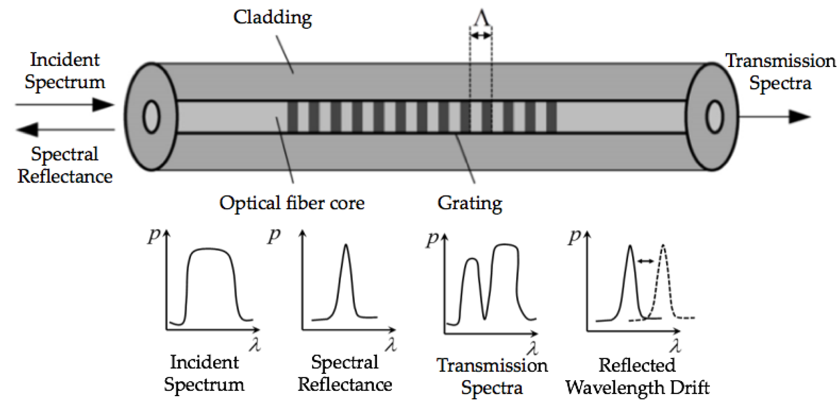
2.1. The Principle of the FBG Sensor

The FBG sensor is a type of optical fiber sensor whose refractive index changes periodically along the fiber axis, and its structure is composed of cladding, grating, and optical fiber (see Figure 4). When broadband light passes through the FBG sensor, the incident light spectrum whose wavelength meets the fiber Bragg reflection condition will be reflected, and the rest will be transmitted through, from the other end of the fiber core [22,23].
The wavelength of the light spectrum that satisfies the reflection condition can be written as follows:
λ B = 2 n e f f Λ
where λ B is the center wavelength of the FBG sensor, n e f f is the effective refractive index, and Λ is the length of the period. When the stress to which the FBG sensor is subjected changes, the length of period Λ as well as the refractive index n e f f will change, resulting in a change in the center wavelength λ B . By measuring the center wavelength λ B before and after external stress is applied, the unknown physical quantity being measured can be obtained. However, when the FBG sensors are packaged by CFRP and pasted on the blade surface, the stress to which the FBG sensor is subjected will be influenced by the packaging layer and bonding layer, and the effective refractive index n e f f and the length of the period Λ will not be equal to the original ones. Moreover, if the packaging layer and bonding layer are damaged or degraded, the measurement accuracy cannot be assured.

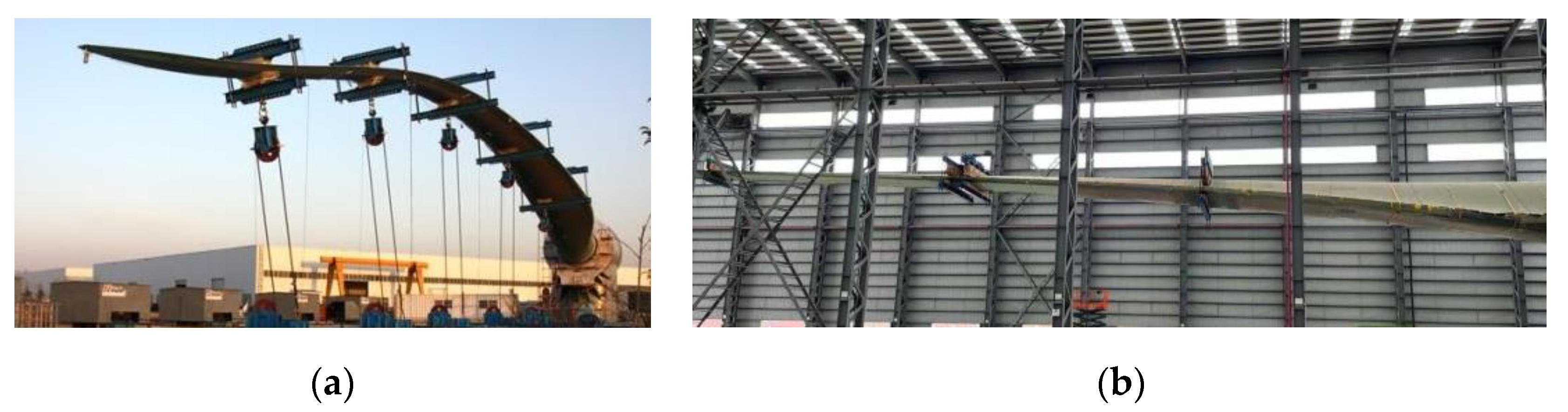
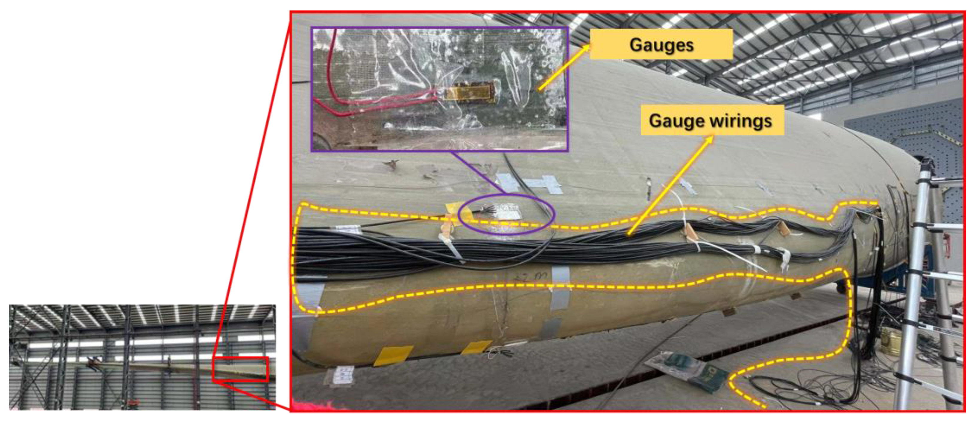
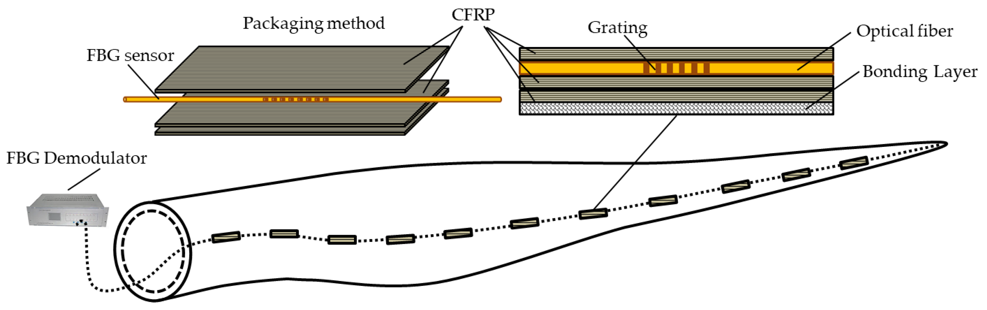
2.2. The Structure of CFRP-packaged FBG Sensors Used in WTB Full-Scale Structural Testing

A CFRP-packaged FBG sensor is a kind of “sandwich” structure, which mainly includes (see Figure 5): FBG sensor (FBG), CFRP packaging layer (PL), and bonding layer (BL). The PL is used to protect the FBG sensor, which contains a layer of carbon fiber placed above the FBG sensor and another two layers placed below. The BL is used to bond the CFRP-packaged FBG sensor to the blade surface. A certain number of CFRP-packaged FBG sensors are series linked by connecting components (CC), and finally connected to the FBG demodulator (FBG-D).
The strain transfer process of the CFRP-packaged FBG sensor is shown in Figure 6. In particular, the axial strain of the blade surface occurs under the action of external load, and in turn, it transfers from the blade surface to the bonding layer, the packaging layer, and the FBG sensor by shear force, and then the optical fiber generates axial strain, which causes the wavelength of the grating to change [24].

3. Reliability Analysis of CFRP-Packaged FBG Sensors Using the FMEA Technique

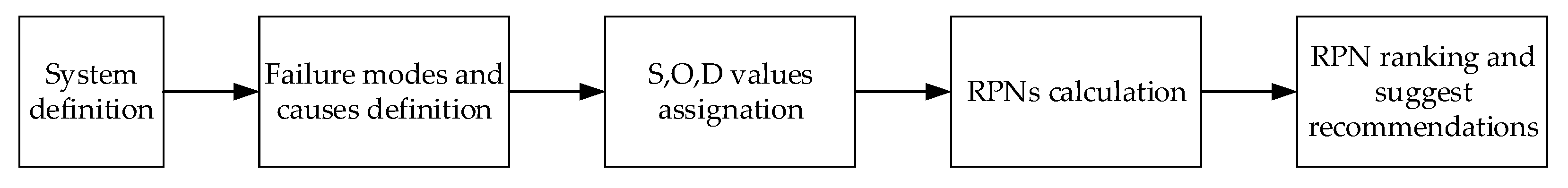
3.1. A Brief Introduction of the FMEA Technique

FMEA is a systemic process to ascertain critical failure items, and the results can show the failure modes, failure causes, as well as their related components or subsystems. The FMEA method is a bottom-up analysis program and its analysis flow is shown in Figure 7. For more information about FMEA, please refer to [11,12,13,14,18,19,20].
FMEA adopts the risk priority number (RPN): the product of three indices: severity (S), occurrence (O), and detection (D), to assess the risk of one certain failure item, where severity represents the consequence of a failure, occurrence denotes a failure’s likelihood, and detection reflects the ability of a failure to be observed.
In engineering projects, the RPNs can be calculated by [20]:
RPN = A(S) × A(O) × A(D)
where A(S), A(O), and A(D) are the average values of severity, occurrence, and detection given by the specialists.

3.2. FMEA of CFRP-Packaged FBG Sensors

Due to the harsh working conditions and long-periodic alternating load, the CFRP-packaged FBG sensors will be subjected to various failures in the process of WTB full-scale structural testing. On the basis of the failure data of the CFRP-packaged FBG sensors collected in the WTB full-scale structural testing, the failure modes, failure causes, and failure effects of the CFRP-packaged FBG sensors are analyzed, and the FMEA table is produced. In order to rank the relative importance of the failure modes and failure causes, components of the CFRP-packaged FBG sensors, namely the severity (S), occurrence (O), and detection (D) of each failure item, are assessed by eight specialists with diverse backgrounds (Table 1). The rating scales of the severity (S), occurrence (O), and detection (D) refer to the standards that have been commonly used in FMEAs of electronic component or composite-composed systems (Table 2). The FMEA of the CFRP-packaged FBG sensor is shown in Table 3.

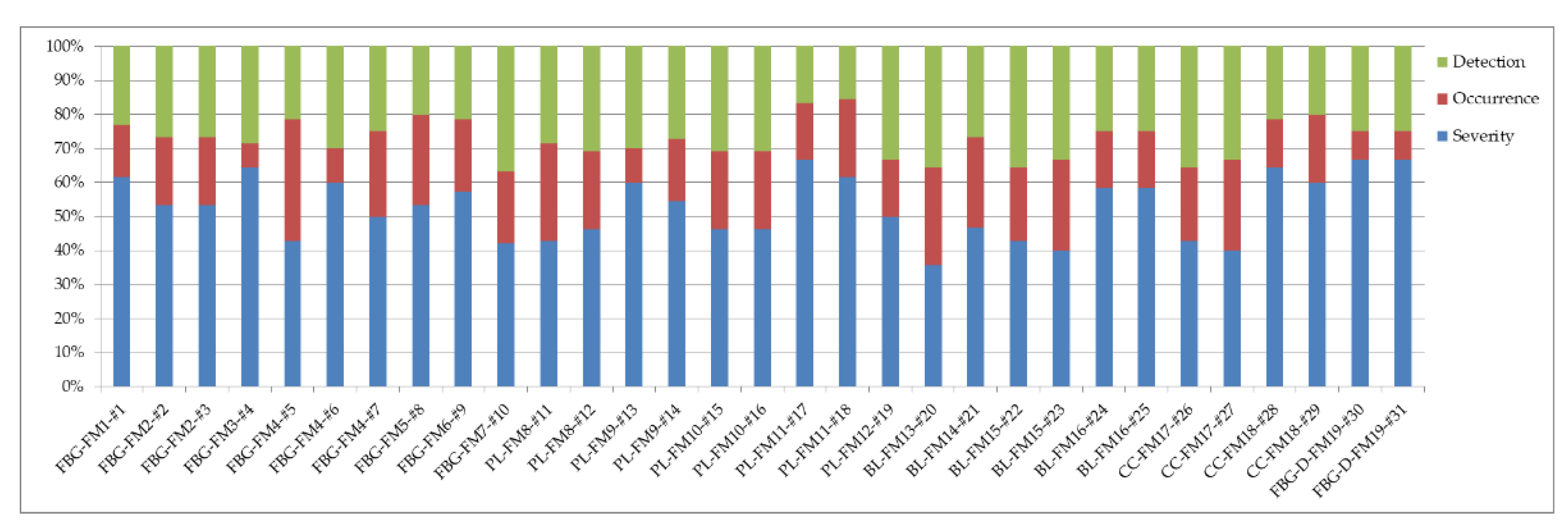
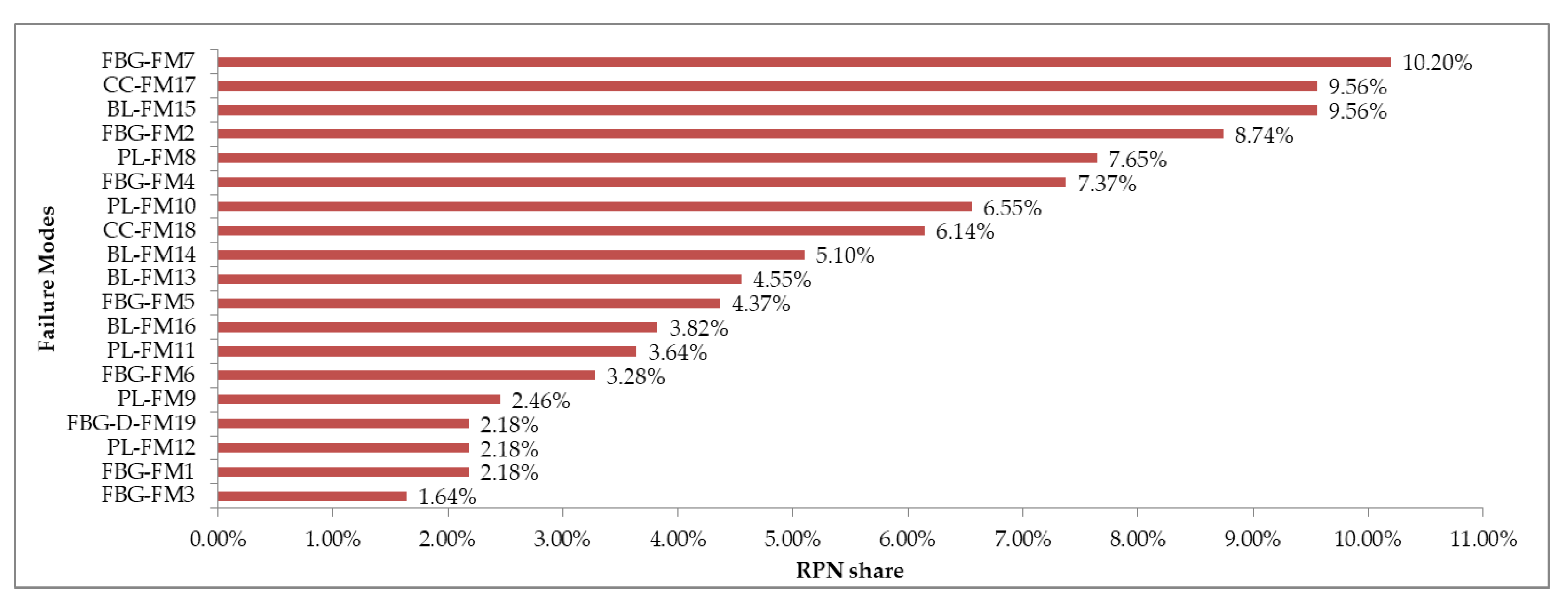
3.3. Results and Discussion

Under the coupling influence of harsh working conditions and long-periodic alternating load, the CFRP-packaged FBG sensors showed a variety of failure modes. By evaluating the severity (S), occurrence (O), and detection (D), the RPNs of the 31 failure modes can be obtained (Table 3). In order to provide more information for operation and maintenance of the CFRP-packaged FBG sensors, the relative importance of the three indices is compared by computing their proportionalities in the RPN of each failure mode (Figure 8). From Figure 8, we can infer that most failure modes of the CFRP-packaged FBG sensor happen slightly or occasionally. Once the CFRP-packaged FBG sensor is in fault, the measurement accuracy cannot be ensured. Fortunately, most failure modes are easily detected; thus, periodical inspection and maintenance are essential.
Furthermore, critical failure modes of each subsystem are analyzed by computing the RPN share (Figure 9). For FBG sensors, most failure modes are related to specific installation operations, such as failure cause #1–#7; thus, a standardized operation process is necessary. Significantly, the failure mode FBG-FM7 has the highest RPN share (10.20%), for it is directly related to measurement accuracy and is comprehensively affected by the packaging layer, bonding layer, and others; thus, periodical calibration is essential. It is noteworthy that the unusable FBG sensors (caused by #1, #4, #8, #9, #28, and #29) do not have a higher RPN share, and although unusable FBG sensors will cause a short data loss, it is easy for the failed FBG sensors to be immediately detected and replaced. The most concerning problem in the CFRP-packaged FBG sensors is the falling measurement accuracy caused by system performance degradation, especially the degradation of PL and BL. For PL, most failure modes happen in the later stage of WTB fatigue testing, and they are mainly caused by complex force conditions (see failure cause #11, #12, #14, #15, and #17–#19). The failure mode PL-FM8 (with a total of 7.65% RPN shares) should be taken note of, for it is difficult to observe without the help of instruments. For BL, most failure modes are related to the bonding process (see failure cause #21–#24), which are manually operated. The adhesive types, the size of the bonding layer, the stress conditions during the fatigue test, etc., will affect the bonding performance. Though the influence of the bonding process on the measurement accuracy of FBG sensors has been studied previously [8,10], a unified pasting process has not been formed at present. For CC, CC-FM17 (with a total of 9.56% RPN shares) is the main failure mode. It reduces the transmission distance and immediately affects the allowable number of FBG sensors on each channel. For FBG-D, its reliability is relatively high compared with other subsystems, as the FBG demodulator is a fairly mature product and it is placed indoors.

4. Reliability Analysis of CFRP-Packaged FBG Sensors Using the FTA Technique

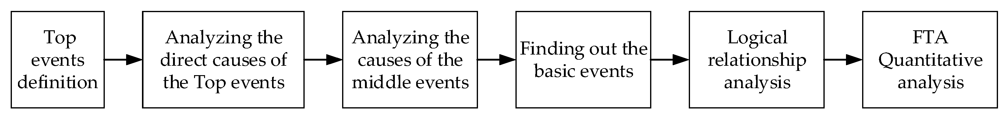
4.1. A Brief Introduction of the FTA Techique

Fault tree analysis (FTA) takes the unexpected fault event (top event) of the system as the target, finds out all the direct and potential factors leading to the occurrence of the top event step by step, and builds the logical relationship between the system and the basic events into an inverted tree graph through the corresponding logic gate symbols [15,16,17,18]. The general FTA analysis process is shown in Figure 10.

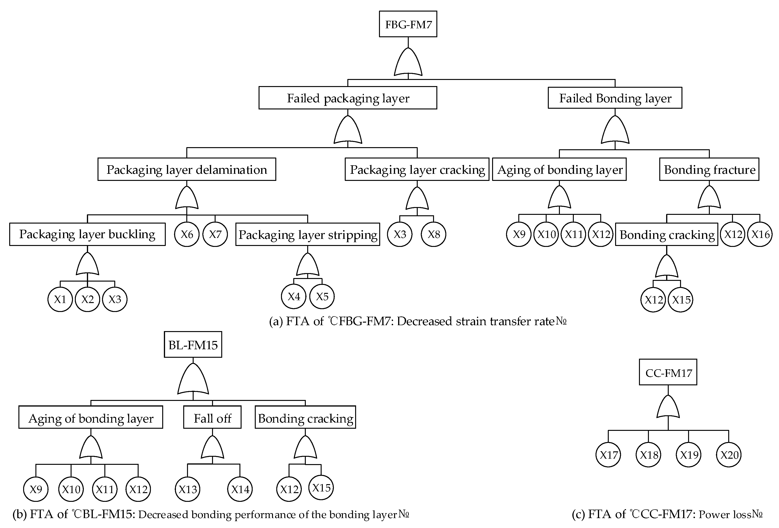
4.2. FTA of CFRP-Packaged FBG Sensors

The failure modes with higher RPN are defined as the key faults [25]. According to Section 3, the 19 failure modes of CFRP-packaged FBG sensors are listed in descending order by their RPN shares (Figure 11). From Figure 11, it can be seen that the failure modes with the highest RPN share are “FBG-FM7 (with RPN share 10.20%)”, “BL-FM15 (with a total of 9.56% RPN shares)”, and “CC-FM17 (with a total of 9.56% RPN shares)”.
The fault trees of the three key faults are established, as shown in Figure 12, and the detailed information of fault events in fault trees is shown in Table 4.

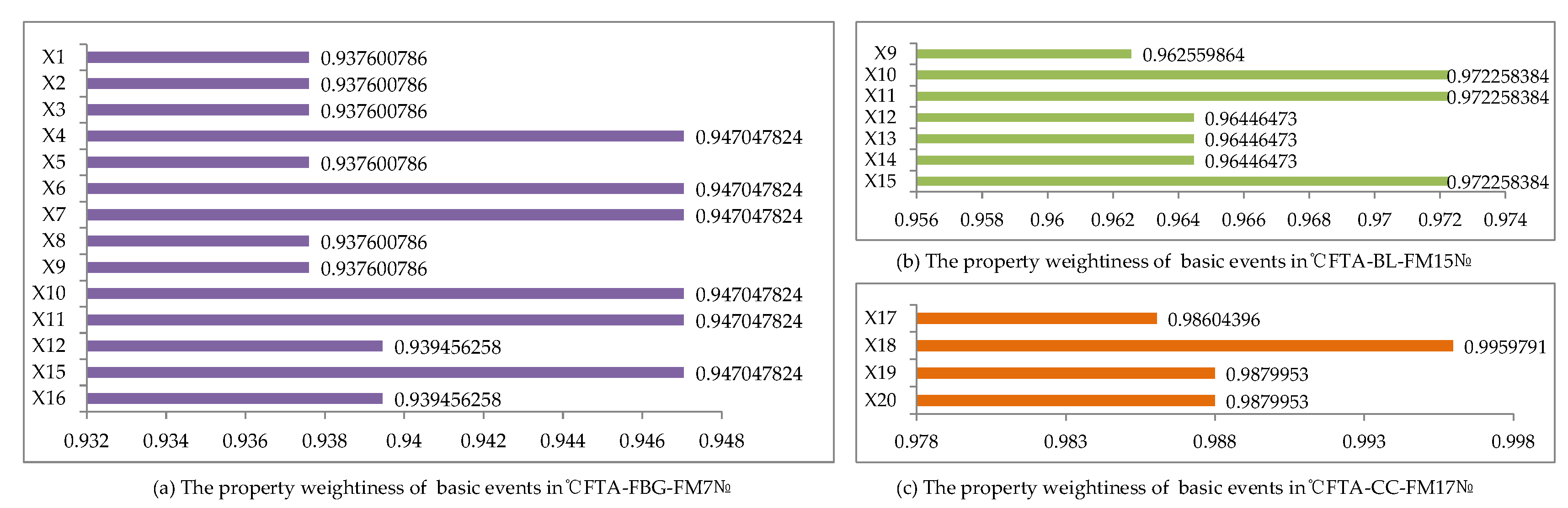
4.3. Results and Discussion

By analyzing the minimum cut sets of each fault tree, we can ascertain the weak links of the system. In this paper, the minimum cut sets of each fault tree are obtained using the descending method, as shown in Table 5.
The failure probabilities of each fault event are given according to the WTB’s field tests, laboratory tests, laboratory simulation test, and expert opinion (Table 6).
Without considering the correlation between basic events, the failure probability of the three top events can be calculated:
P ( T ) = P ( K 1 K 2 K r ) = i = 1 r P ( K i ) i < j = 2 r P ( K i K j ) + i < j < k = 3 r P ( K i K j K j ) + + ( 1 ) r 1 P ( K 1 K 2 K r ) i = 1 r P ( K i )
where K i , K j , K j are the i-th, j-th, and k-th minimum cut sets, respectively, and r is the number of the minimum cut set. Thus, the failure probabilities of “FBG-FM7”, “BL-FM15”, and “CC-FM17” are 0.06242, 0.03554, and 0.01398, respectively.
The property weightiness of basic events in each FTA can be calculated:
Δ g i ( t ) = F s ( t ) F i ( t )
where F s ( t ) , F i ( t ) are the failure probability of the top event and the basic event, respectively. The property weightiness of basic events in FTAs of “FBG-FM7”, “BL-FM15”, and “CC-FM17” are shown in Figure 13. From Figure 13, we can infer that the property weightiness of all basic events are approximately equivalent. The reason is related to the production and arrangement process of the CFRP-packaged FBG sensors, which are mainly manually operated without unified standards. In addition, the key faults of “FBG-FM7”, “BL-FM15”, and “CC-FM17” are mainly caused by the manufacturing process (see X1–X3, X6, X9, X10, etc.) and stress conditions (X4–X6, X7, X8, etc.); thus, further study on the standard manufacturing process, the periodic quality testing of the PL, BL, and CC, and the routine calibration of FBG sensors is important.

5. Conclusions

CFRP-packaged FBG sensors are widely used in WTB full-scale structural testing, and their quality and reliability have attracted a lot of attention. In this paper, FMEA and FTA techniques are used to complete the reliability analysis of CFRP-packaged FBG sensors. The failure modes, failure causes, and failure effects are analyzed for each of the FBG sensors, PL, BL, CC, and the FBG demodulator. The three key faults (“FBG-FM7”, “BL-FM15”, and “CC-FM17”) are defined and their corresponding FTAs are built. Recommendations to mitigate the identified key failures are discussed. However, the FMEA and FTA methods used in this paper are based on precise probability theory without considering cognitive uncertainty, such as the assessment of severity (S), occurrence (O), and detection (D), or the definition of system or component failures, etc. Specifically, the RPN calculation method in this paper does not consider the weight of each index. Thus, in the future, other alternative methods for risk evaluation such as action priority [13,18], fuzzy sets [25,26], Bayesian network [26,27], interval analysis [28], etc., will be implemented.

Author Contributions

Conceptualization, Z.L. (Zheng Liu), Y.L., N.Z., Z.L. (Zhongwei Liang) and F.L.; methodology, Z.L. (Zheng Liu) and Y.L.; software, Z.L. (Zheng Liu) and Y.L.; validation, N.Z., Z.L. (Zhongwei Liang) and F.L.; investigation, Y.L.; data curation, Y.L.; writing—original draft preparation, Y.L.; writing—review and editing, Z.L. (Zhongwei Liang) and F.L.; supervision, Z.L. (Zheng Liu); project administration, Z.L. (Zhongwei Liang); funding acquisition, Z.L. (Zheng Liu) and Z.L. (Zhongwei Liang). All authors have read and agreed to the published version of the manuscript.

Funding

This research was funded by National Natural Science Foundation of China, grant number 51905116; National Key R&D Program of China, grant number 2018YFB1501200, and National Key R&D Program of China, grant number 2018YFB2000501.

Acknowledgments

The paper was partially supported by the National Natural Science Foundation of China (51905116), the National Key R&D Program of China (2018YFB1501200), and the National Key R&D Program of China (2018YFB2000501).

Conflicts of Interest

The authors declare no conflict of interest.

References

  1. Zhou, H.F.; Dou, H.Y.; Qin, L.Z.; Chen, Y.; Ni, Y.Q.; Ko, J.M. A review of full-scale structural testing of wind turbine blades. Renew. Sustain. Energy Rev. 2014, 33, 177–187. [Google Scholar] [CrossRef]
  2. Li, H.; Guedes Soares, C.; Huang, H.Z. Reliability analysis of floating offshore wind turbine using Bayesian Networks. Ocean. Eng. 2020, 217, 107827. [Google Scholar] [CrossRef]
  3. International Standard IEC61400-23 Wind Turbines-Part 23: Full-Scale Structural Testing of Rotor Blades; International Electrotechnical Commission: Geneva, Switzerland, 2014.
  4. GB/T 25384-2010: Full Scale Structural Test of Wind Turbine Blade; Standards Press of China: Beijing, China, 2010.
  5. Arsenault, T.J.; Achuthan, A.; Coppotelli, G.; Grappasonni, C. Development of a FBG based distributed strain sensor system for wind turbine structural health monitoring. Smart Mater. Struct. 2013, 22, 075027. [Google Scholar] [CrossRef]
  6. Tian, S.; Yang, Z.; Chen, X.; Xie, Y. Damage detection based on static strain responses using FBG in a wind turbine blade. Sensors 2015, 15, 19992–20005. [Google Scholar] [CrossRef] [PubMed] [Green Version]
  7. Wen, C.J.; Li, Y.L.; Wang, Y.B. High temperature failure and spectral characteristics of metallized fiber grating. Laser Infrared 2016, 46, 481–485. [Google Scholar]
  8. Liu, H. Study on the Repeatability, Ronsistency and Fatigue Properties of Adhesive Packaged FBG Strain Sensors. Ph.D. Thesis, Wuhan University of Technology, Wuhan, China, 2014. [Google Scholar]
  9. Zhang, W. Research on Key Technologies of reliability of FBG strain sensing system. Ph.D. Thesis, Chongqing University, Chongqing, China, 2016. [Google Scholar]
  10. Liu, Z.; Liu, X.; Zhu, S.P.; Zhu, P.; Liu, W.; Correia, J.A.; De Jesus, A.M. Reliability assessment of measurement accuracy for FBG sensors used in structural tests of the wind turbine blades based on strain transfer laws. Eng. Fail. Anal. 2020, 112, 104506. [Google Scholar] [CrossRef]
  11. IEC. Analysis Techniques for System Reliability—Procedure for Failure Mode and Effects Analysis (FMEA) (IEC 60812); International Electrotechnical Commission: Geneva, Switzerland, 2006. [Google Scholar]
  12. Li, H.; Teixeira, A.P.; Guedes Soares, C. A two-stage Failure Mode and Effect Analysis of offshore wind turbines. Renew. Energy 2020, 162, 1438–1461. [Google Scholar]
  13. Xiao, N.; Huang, H.Z.; Li, Y.; He, L.; Jin, T. Multiple failure modes analysis and weighted risk priority number evaluation in FMEA. Eng. Fail. Anal. 2011, 18, 1162–1170. [Google Scholar]
  14. Yang, J.; Huang, H.Z.; He, L.P.; Zhu, S.P.; Wen, D. Risk evaluation in failure mode and effects analysis of aircraft turbine rotor blades using Dempster-Shafer evidence theory under uncertainty. Eng. Fail. Anal. 2011, 18, 2084–2092. [Google Scholar]
  15. Kabir, S. An overview of fault tree analysis and its application in model based dependability analysis. Expert Syst. Appl. 2017, 77, 114–135. [Google Scholar] [CrossRef] [Green Version]
  16. Huang, H.Z.; Zhang, H.; Li, Y.F. A new ordering method of basic events in fault tree analysis. Qual. Reliab. Eng. Int. 2012, 28, 297–305. [Google Scholar] [CrossRef]
  17. Li, Y.F.; Mi, J.; Liu, Y.U.; Yang, Y.J.; Huang, H.Z. Dynamic fault tree analysis based on continuous-time Bayesian networks under fuzzy numbers. Proc. Inst. Mech. Eng. Part O J. Risk Reliab. 2015, 229, 530–541. [Google Scholar] [CrossRef]
  18. Li, H.; Díaz, H.; Guedes Soares, C. A failure analysis of floating offshore wind turbines using AHP-FMEA methodology. Ocean. Eng. 2021, 234, 109261. [Google Scholar] [CrossRef]
  19. Liu, J.; Chen, T.; Zhang, Y.; Wen, G.; Qing, Q.; Wang, H.; Sedaghati, R.; Xie, Y.M. On sound insulation of pyramidal lattice sandwich structure. Compos. Struct. 2019, 208, 385–394. [Google Scholar] [CrossRef] [Green Version]
  20. Li, H.; Díaz, H.; Guedes Soares, C. A developed failure mode and effect analysis for floating offshore wind turbine support structures. Renew. Energy 2021, 164, 133–145. [Google Scholar] [CrossRef]
  21. Knežević, V.; Orović, J.; Stazić, L.; Čulin, J. Fault tree analysis and failure diagnosis of marine diesel engine turbocharger system. J. Mar. Sci. Eng. 2020, 8, 1004. [Google Scholar] [CrossRef]
  22. More, A.S.; Lad, P.S.; Krishnan, S.R.; Bhosale, S.R. Performance analysis of Strain sensor based on Fiber Bragg Grating. ITM Web Conf. 2020, 32, 02006. [Google Scholar] [CrossRef]
  23. Karatas, C.; Degerliyurt, B.; Yaman, Y.; Sahin, M. Fibre Bragg grating sensor applications for structural health monitoring. Aircr. Eng. Aerosp. Technol. 2019, 92, 355–367. [Google Scholar] [CrossRef]
  24. Kim, S.W. Characteristics of strain transfer and the reflected spectrum of a metal-coated fiber Bragg grating sensor. Opt. Lasers Eng. 2017, 96, 83–93. [Google Scholar] [CrossRef]
  25. Huang, H.Z.; Tong, X.; Zuo, M.J. Posbist fault tree analysis of coherent systems. Reliab. Eng. Syst. Saf. 2004, 84, 141–148. [Google Scholar] [CrossRef]
  26. Li, Y.F.; Huang, H.Z.; Mi, J.; Peng, W.; Han, X. Reliability analysis of multi-state systems with common cause failures based on Bayesian network and fuzzy probability. Ann. Oper. Res. 2019. [Google Scholar] [CrossRef]
  27. Li, Y.F.; Liu, Y.; Huang, T.; Huang, H.Z.; Mi, J. Reliability assessment for systems suffering common cause failure based on Bayesian networks and proportional hazards model. Qual. Reliab. Eng. Int. 2020, 36, 2509–2520. [Google Scholar] [CrossRef]
  28. Mi, J.; Li, Y.F.; Peng, W.; Huang, H.Z. Reliability analysis of complex multi-state system with common cause failure based on evidential networks. Reliab. Eng. Syst. Saf. 2018, 174, 71–81. [Google Scholar] [CrossRef]
Figure 1. WTB full-scale structural testing: (a) static testing; (b) fatigue testing.
Applsci 11 10859 g001
Figure 2. Gauge and gauge wirings in WTB full-scale structural testing.
Applsci 11 10859 g002
Figure 3. CFPP-packaged FBG sensors in WTB full-scale structural testing.
Applsci 11 10859 g003
Figure 4. The structure of FBG sensors.
Applsci 11 10859 g004
Figure 5. The structure of CFRP-packaged FBG sensors and their application on a WTB.
Applsci 11 10859 g005
Figure 6. Strain transfer process of a CFRP-packaged FBG sensor.
Applsci 11 10859 g006
Figure 7. Flow chart of failure mode and effects analysis.
Applsci 11 10859 g007
Figure 8. The RPN of failure modes of CFRP-packaged FBG sensors.
Applsci 11 10859 g008
Figure 9. The RPN and RPN shares of each subsystem: (a) RPN and RPN shares of FBG failures; (b) RPN and RPN shares of PL failures; (c) RPN and RPN shares of BL failures; (d) RPN and RPN shares of CC failures; (e) RPN and RPN shares of FBG-D failures.
Applsci 11 10859 g009
Figure 10. Flow chart of fault tree analysis.
Applsci 11 10859 g010
Figure 11. RPN shares of the 19 failure modes of CFRP-packaged FBG sensors.
Applsci 11 10859 g011
Figure 12. FTA of “FBG-FM7”, “BL-FM15”, and “CC-FM17”.
Applsci 11 10859 g012
Figure 13. The property weightiness of basic events in FTAs of “FBG-FM7”, “BL-FM15”, and “CC-FM17”.
Applsci 11 10859 g013
Table 1. Specialists involved in failure analysis of the CFRP-packaged FBG sensors.
CodeEmployerDutyWorking Period
1Wind Energy CompanyQuality Engineer8 Years
2Wind Energy CompanyTest engineer6 Years
3Wind Energy CompanyTest engineer5 Years
4FBG sensor CompanyComponents Design14 Years
5FBG sensor CompanyQuality Engineer5 Years
6UniversityResearcher8 Years
7UniversityResearcher8 Years
8UniversityResearcher4 Years
Table 2. Rating scales of S, O, and D of FMEA of the CFRP-packaged FBG sensors.
RatingSeverity (S) Occurrence (O)Detection (D)
1Effect is not noticedExtremely lessCertain
2Very slight effectRemoteVery high
3Slight effect causing annoyanceVery slightHigh
4Slight effect causing return of productSlightModerate
5Moderate effect causing return of productOccasionalMedium
6Significant effectModerateLow chance
7Major effectFrequentSlight
8Extreme effect, system inoperableHighRemote
9Critical effect, system shutdownVery highVery remote
10Hazardous, without warningExtremely highNo inspection
Table 3. Failure modes and their causes and effects on the CFRP-packaged FBG sensor.
Failure Mode LevelFailure Cause LevelRPN Level
SystemCode of FMFailure ModesFailure EffectsCodeFailure CausesA(S)A(O)A(D)RPNs
FBGFM1Grating brokenUnusable FBG sensor#1Rough construction82348
FM2Sidelobe interferenceMultiple peaks#2Excessive splicing loss83496
#3Packaging process errors83496
FM3No outputUnusable FBG sensor#4Small turning radius of the ending grating91436
FM4MisinformationInaccurate measurement results#5Unstable supply voltage65390
#6Dust existing in the transmitter or receiver61318
#7Insufficient transmitter or receiver power63354
FM5Signal driftUnusable FBG sensors#8Jamming external environment84396
FM6Discontinuous signalsUnusable FBG sensors#9Jamming external environment83372
FM7Decreased strain transfer rateInaccurate measurement results#10Changed bonding parameters or packaging parameters847224
PLFM8DelaminationDecreasing compressive strength and buckling limit#11Under impact force64496
#12Interlamination Stress between resin and prepreg63472
FM9CrackingInaccurate strain measurement results and reduced service life#13Single direction of carbon fiber prepreg61318
#14Stress concentration at the changing section62336
FM10BucklingMaterial deformation and inaccurate strain measurement results#15Excessive temperature and pressure during packaging63472
#16Asymmetric CFRP layers63472
FM11CrackDamaged packaged layer, or failed FBG sensors#17Excessive transverse shear and eccentric longitudinal stress82232
#18Uneven stress83248
FM12StrippingSeparated packaged layer, or inaccurate strain measurement results#19Stress concentration and excessive load62448
BLFM13Ageingdecreasing bonding strength and mechanical properties#20Temperature–moisture coupling environment, or residual internal stress545100
FM14Fall offSeparated CFRP-packaged FBG sensors and unreliable monitoring information#21Small bonding thickness or poor material properties744112
FM15CrackReduced mechanical properties, service life, and inaccurate strain measurement results#22Unsuitable curing temperature63590
#23Residual stress and stress concentration645120
FM16FractureBonding failures, easily falling CFRP-packaged FBG sensors, and inaccurate strain measurement results#24Cracks in the bonding layer72342
#25Stress concentration and excessive load72342
CCFM17Power lossReduced transmission distance, abnormal data transmission, and inaccurate strain measurement results#26Bad welding process, or mismatch structure parameters63590
#27Fiber bending loss, Rayleigh scattering loss, or light wave absorption loss645120
FM18Fiber brokenUnusable FBG sensors#28Over bending of optical fiber92354
#29Stress concentration and excessive load93381
FBG-DFM19Work failureFailed signal and data acquisition#30Abnormal external factors and internal quality defects81324
#31Improper human operation81324
A(S), A(O), and A(D) are the average values of severity, occurrence, and detection of the employed specialists.
Table 4. The detailed information of fault events in fault trees.
No.Basic EventNo.Basic EventNo.Basic Event
X1Too high temperature in packaging processX8Stress concentrationX15Unsuitable curing temperature
X2Excessive pressure in packaging processX9Affected by temperatureX16Stress concentration in bonding layer
X3Asymmetric CFRP layersX10Temperature–moisture coupling environmentX17Mismatch structure parameters
X4Stress concentration at the changing sectionX11Affected by alternating loadX18Fiber bending loss
X5Excessive load in packaging processX12Residual internal stress in bonding layerX19Rayleigh scattering loss
X6Under impact forceX13Small bonding thicknessX20light wave absorption loss
X7Interlamination Stress X14Poor bonding materials
Xi is the basic event in FTA.
Table 5. The minimum cut sets of each key fault.
Top EventsMinimum Cut Sets
FBG-FM7: Decreased strain transfer rate14
BL-FM15: Decreased bonding performance of the bonding layer7
CC-FM17: Power loss4
Table 6. Failure probability of each basic event.
No.Failure ProbabilityNo.Failure ProbabilityNo.Failure ProbabilityNo.Failure Probability
X14 × 10−4X610−2X1110−2X162 × 10−3
X24 × 10−4X710−2X122 × 10−3X174 × 10−4
X34 × 10−4X84 × 10−4X132 × 10−3X1810−2
X410−2X94 × 10−4X142 × 10−3X192 × 10−3
X54 × 10−4X10¹⁰−2X1510−2X202 × 10−3
Publisher’s Note: MDPI stays neutral with regard to jurisdictional claims in published maps and institutional affiliations.

