3.1. Microstructure and Phase Compositions of the Multi-Phase Coatings
The compositions of the fabricated Cu-Ti films on the surface of the C61900 Cu alloy measured by EDS are listed in
Table 4. The Cu-Ti film with Ti/Cu atomic ratios was close to 7:1, 7:4, and 1:2 for F1, F2, and F3.
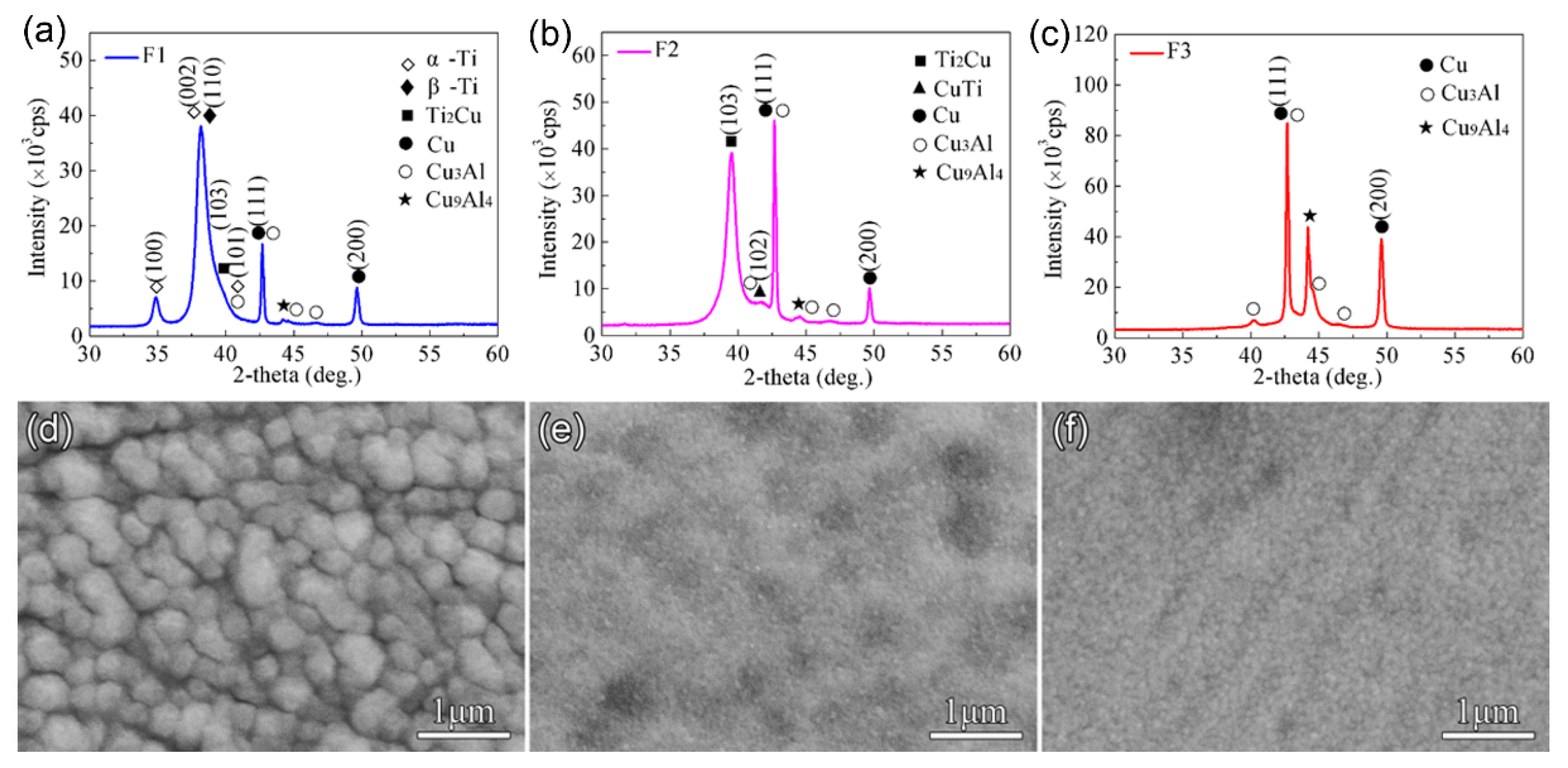
Figure 1 shows XRD patterns of the Cu-Ti films obtained on the C61900 Cu alloy. The composed phases differed depending on the Ti/Cu atomic ratio. Specifically, the crystalline phases of the F1 film were mainly
β-Ti phase, Ti
2Cu phase, and a trace of
α-Ti phase, as shown in
Figure 1a. The intense peak at 2
θ = 38.2° was from
β-Ti rather than
α-Ti, where the formation of
β-Ti phase was promoted by the Cu substrate for the same body-centered cubic structure. In comparison, the main phases of the F2 film were Ti
2Cu and a small amount of CuTi phase, while the F3 film contained no crystalline Cu-Ti phase, as shown in
Figure 1b,c, respectively. The surface morphology of the Cu-Ti films also changed, as shown in
Figure 1d–f, where the F1 film was smooth with uniform particles, and the F2 and F3 films were much finer.
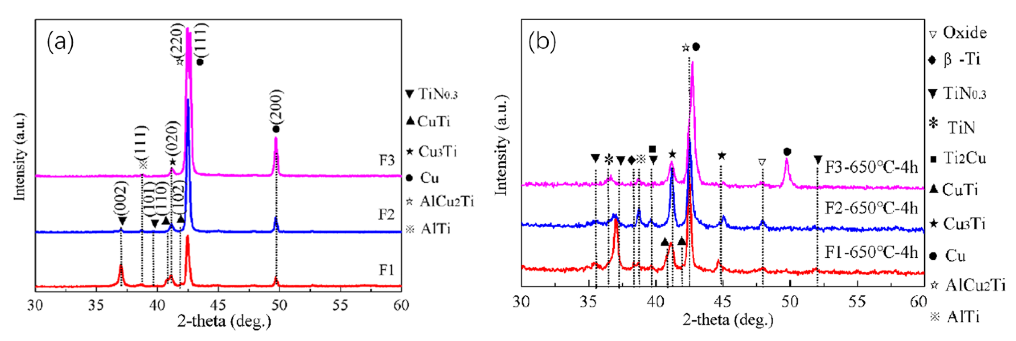
The three Cu-Ti films prepared on the C61900 Cu alloy were then treated by plasma nitriding at 650 °C for 4 h. Except for the Cu-Ti intermetallics and Ti-N compounds, an AlCu
2Ti phase also formed after plasma nitriding, as shown in
Figure 2a. The grazing incidence XRD of the Cu-Ti films after nitriding at 650 °C indicated that the TiN and TiN
0.3 phases existed in the outmost layer, and the diffraction peak of the Cu
3Ti and AlTi phases in the F2 film coated surface was enhanced simultaneously after nitriding at 650 °C for 4 h, as shown in
Figure 2b.
After nitriding at 650 °C for 4 h, the surface morphology of the Cu-Ti films changed, as shown in
Figure 3. The discontinuous white Fe-rich phase formed on the surface, which was attributed to the sputtering of the Fe element in the hollow cathode net, as indicated by the EDS results for the selected area. For F2 and F3 films, the size of the Fe-rich phase particles became larger (about 2–3 μm). In addition, no Cu element for F1 film after nitriding was detected, and the Cu content on the surface of F3 film decreased.
3.2. Mechanical Properties of the Multi-Phases Coatings
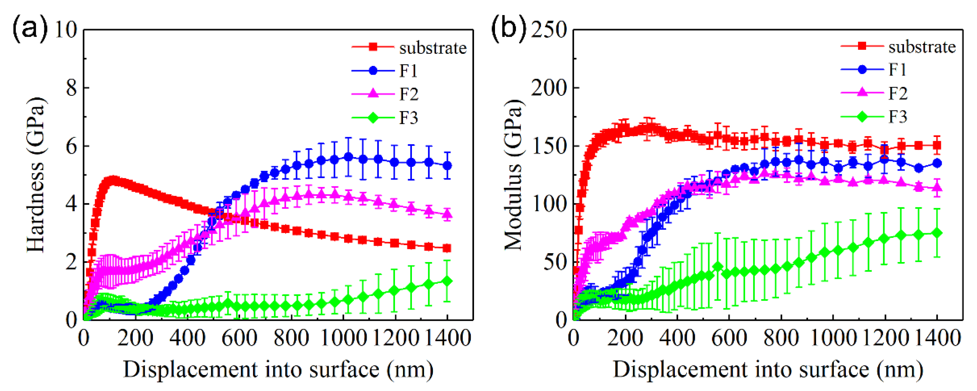
The change in the hardness and elastic modulus of C61900 Cu alloy with increasing indented depth is shown in
Figure 4. The hardness of the unmodified C61900 Cu alloy substrate increased rapidly up to 6 GPa and then decreased gradually with the growth of depth, which was kept constant at 3 GPa. The elastic modulus of the C61900 Cu alloy shared the same trend until it reached about 125 GPa. The increase in the early hardness and modulus was attributed to the size effect and work hardening effect. For the multi-phase coatings, the hardness of the modified layer at 0–300 nm from the surface was lower than the C61900 Cu alloy for the F1 and F3 films, and the hardness of the nitrided F2 film was the highest at this stage, which was dependent on the particle size and the surface morphology, as indicated in
Figure 3. The hardness and modulus for the nitrided F1 and F2 films followed the same changing trend. The maximum hardness value of nitrided F1 film and F2 film reached 5.5 GPa and 4 GPa, respectively. A critical indented depth of about 500 nm existed, where the hardness and modulus of the F1 film after nitriding were highest when the depth was over 500 nm.
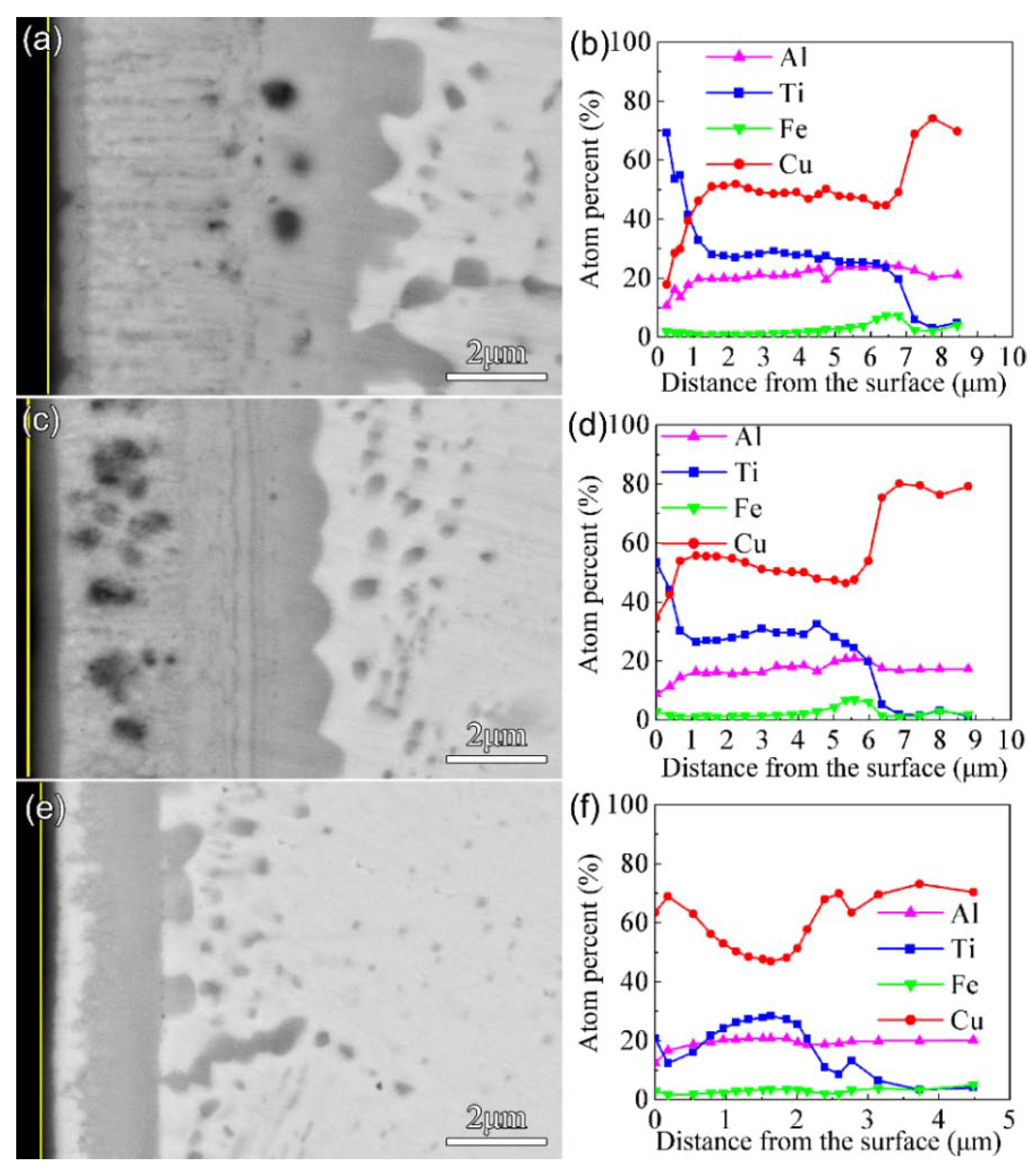
Figure 5 shows the morphology of the cross-sections and the EDS results after nitriding at 650 °C for 4 h. The thickness of the F1, F2, and F3 films after nitriding was 7 μm, 6 μm, and 3 μm, respectively. The Ti content remained at a high level only in a range of about 650 nm from the surface for F1 and F2. Combined with the results of EDS and GIXRD, it was found that the multi-phase coatings consisted of a nitride layer as the outmost surface and a thicker intermediate layer of Cu-Ti and AlCu
2Ti. In addition, a discontinuous Cu-rich layer appeared in the multi-phase coating of the nitrided F3 film. Due to the strong affinity between Ti and N, the Ti-N compounds formed on the surface after nitriding under high nitrogen content, so Cu accumulated in the subsurface.
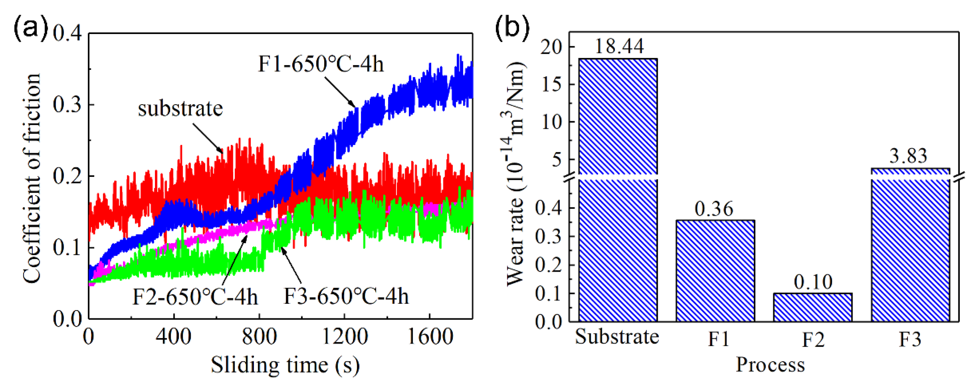
The friction and wear properties of the C61900 Cu alloy and the modified surface were evaluated. The surface topography of the worn track and the friction coefficient of the C61900 Cu substrate against the WC ball showed serious surface wear with a deep worn track of 12.7 μm (as displayed in our previous work [
18]). As shown in
Figure 6a, the friction coefficient of the C61900 Cu alloy was stable at 0.16. In comparison, the friction coefficient of the modified layer of nitrided F2 film and F3 film decreases to 0.1, while the friction coefficient of the nitrided F1 film slowly increased from 0.05 to 0.3. In addition, the wear rates of the F1, F2, and F3 films after plasma nitriding were 3.6 × 10
−15 m
3/Nm, 1.0 × 10
−15 m
3/Nm, and 3.8 × 10
−14 m
3/Nm, respectively, which were 98%, 99.5%, and 79% lower than the matrix, respectively, as shown in
Figure 6b.
The surface morphologies and cross-sectional profiles of worn tracks after nitriding at 650 °C for 4 h showed that peeling of the hard coating was induced during the wear test. The worn depth and width of F1 film reached 1.5 μm and 200 μm, respectively, as shown in
Figure 7a,b. For the nitrided F2 film, only slight scratch marks remained on the modified layer, with a depth and width of only 0.7 μm and 150 μm, respectively. However, the depth and width of the abrasive groove for the nitrided F3 film reached 4.3 μm and 400 μm, respectively. The EDS results for the A-F region in
Figure 7 are listed in
Table 5. The high O content indicates that oxidation occurred during the wear process. For the nitrided F1 film and F2 film, the N atoms in region B and region D reached 15.9 at.% and 6.7 at.%, respectively, which indicates that the nitrides formed, and this can effectively improve the wear resistance.
The acoustic signal curves and friction force curves of the multi-phase coatings on the C61900 Cu alloy are shown in
Figure 8. The friction force increased slowly as the load grew to be about 18 N, and no change in the acoustic signal was detected. During the scratching test of the modified surfaces, the load continuously increased. When the normal load increased to the critical value, not only did a sudden change in the friction force occur, but also a sharp increase in the acoustic signal could be detected due to the fracture or separation of the multi-phase coatings. Thus, the critical load of failure could be obtained, which was dependent on the coating thickness, the residual stress, and the mechanical properties of the substrate (e.g., hardness), as well as the test parameters (e.g., ram radius and sliding speed) [
33,
34]. With the further increase in the load to 45 N, a spike in the acoustic signal was induced at the critical load, indicating that the brittle coating was broken, as shown in
Figure 8a. For the nitrided F2 film, the critical load for the multi-phase coating was 38 N, and the substrate was gradually exposed at a distance of about 1 mm from the starting point, as shown in
Figure 8b,c. Similarly, for the nitrided F3 film, the friction force gradually increased with the load to about 17 N, and no change in the acoustic signal appeared until the load increased to the critical load of about 44 N. The friction force curve also fluctuated at the intensity peak of the acoustic signal, as shown in
Figure 8d.
It is well known that the wear resistance is closely related to the surface hardness and elastic modulus. In the present work, the wear resistances of the three types of coatings were all improved, although the measured surface hardness of the modified coatings was even lower than that of the Cu substrate at the initial indentation depth (see
Figure 4a). The measured average hardness by the indentation could not reflect the wear resistance appropriately. In addition, the scratching force as well as the acoustic emission signal always showed some fluctuation. Therefore, it is of great importance to study the mechanical properties of the possible formed phases by first principle calculations to provide basic knowledge on the obtained surface properties of the multi-phase coatings.
3.3. The Phase Formation Mechanism and Mechanical Properties
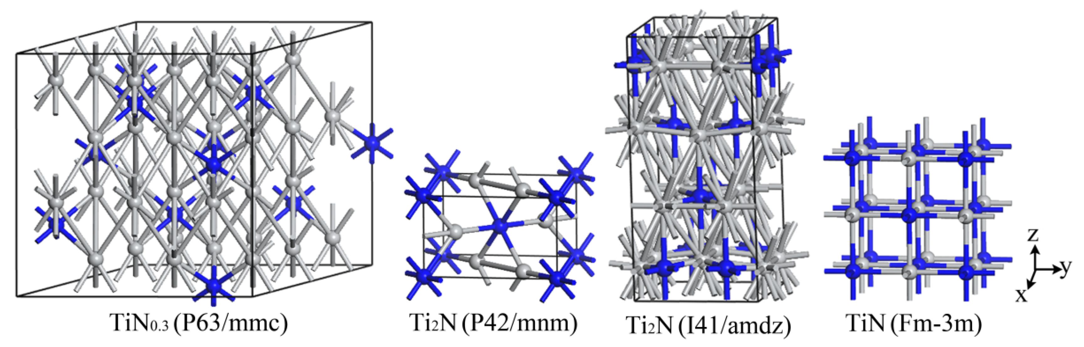
The structure of
α-TiN
0.3 can be regarded as a solid solution of N atoms in the close-packed hexagonal structure of
α-Ti. A 3 × 3 × 2 supercell is built based on the microstructure of
α-Ti, where 11 nitrogen atoms occupy the octahedral space in the Ti
36 super crystal cell without changing the lattice geometry of Ti
36, forming Ti
36N
11 to describe the
α-TiN
0.3 phase. The crystal structure models of the Ti-N system are shown in
Figure 9.
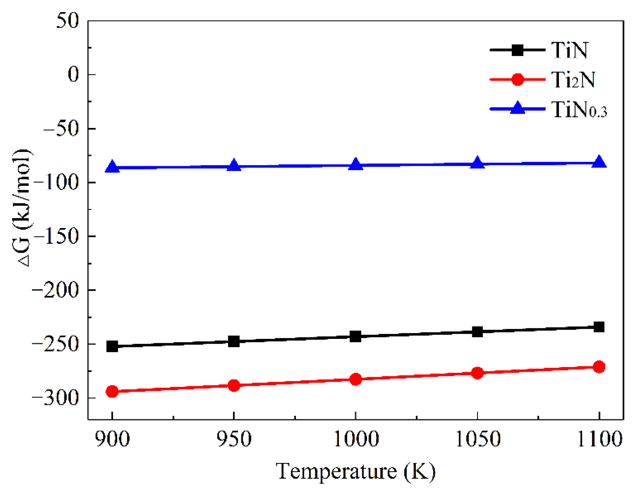
The Gibbs free energy of TiN,
ε-Ti
2N, and TiN
0.3 between 900 K and 1100 K could be obtained, as shown in
Figure 10. The negative Gibbs free energy of these three phases firstly indicated their possible formation; the calculated lattice parameters and the formation enthalpy of the Ti-N intermetallic compounds are listed in
Table 6 and compared with the existing calculation results. The results showed that the higher the N content, the greater the formation enthalpy of the Ti-N compound and the better the thermodynamic stability, namely TiN > Ti
2N(P42/mnm) > TiN
0.3. The calculated elastic constants
Cij of the Ti-N intermetallic compounds, as shown in
Table 7, indicate that all Ti-N compounds are mechanically stable.
The elastic constants were applied to calculate the bulk modulus (
B), shear modulus (
G), Young’s modulus (
E), and Poisson’s ratio (
υ) of the possible phases, as shown in
Table 8. The Vickers hardness for the analyzed phases in the present work can also be obtained based on the following equation [
37],
where
K =
G/
B is Pugh’s ratio.
It can be seen that the calculated elastic modulus was in good agreement with the previous literature. The shear modulus was positively correlated with the phase stability, so Ti
2N (I41/amdz) had poor stability for the lowest shear modulus. The volume modulus (
B), shear modulus (
G), Young’s modulus (
E), and Vickers hardness (
HV) of other Ti-N compounds all met the relationship of TiN > Ti
2N(P42/mnm) > TiN
0.3. That is, with the increase in N content, both the modulus and Vickers hardness increased and were higher than those of the Cu-Ti intermetallics. The brittleness and toughness of the Ti-N compounds were also evaluated by the G/B ratio and Cauchy pressure
C12–
C44 of Pettifor’s principle [
38,
39], which indicated that the TiN, Ti
2N (P42/mnm), and TiN
0.3 all belong to brittle compounds. Therefore, the surface modification layer of C61900 Cu alloy should be designed with the hard Ti-N compound as the outmost layer and the Cu-Ti intermetallics as the middle layer for the compromising hardness.
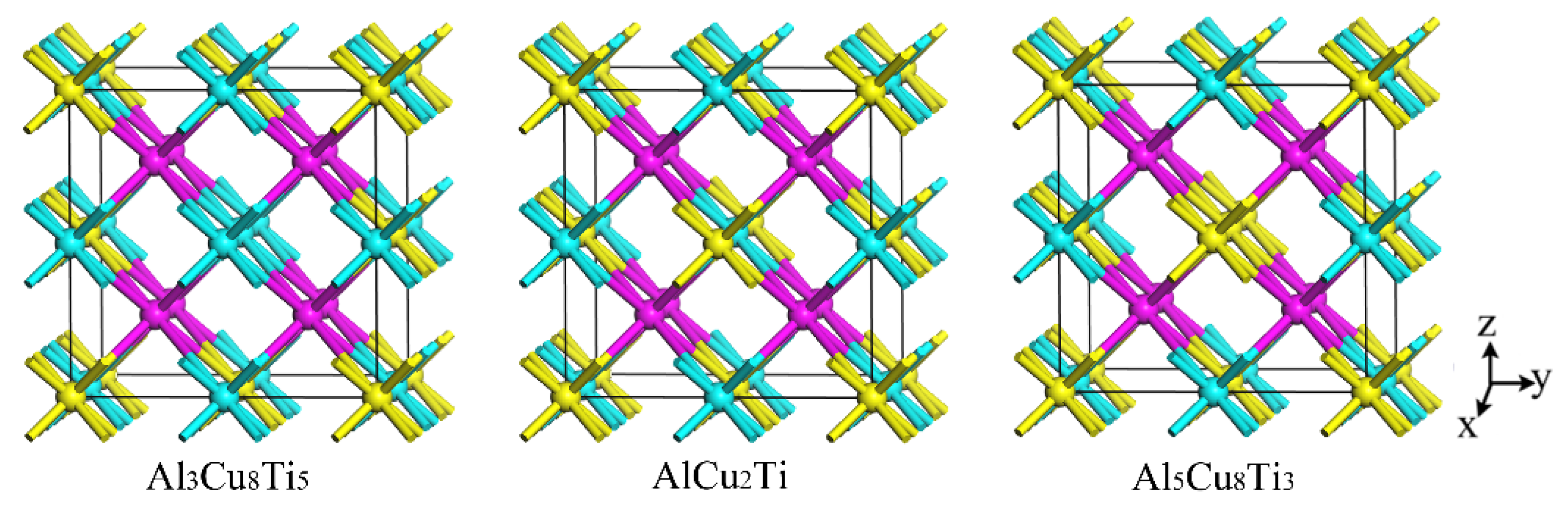
The properties of the AlCu
2Ti, Al
3Cu
8Ti
5, and Al
5Cu
8Ti
3 were also investigated by first-principle calculation. The crystal structures of the four phases are shown in
Figure 11. An Al atom in the AlCu
2Ti phase structure is replaced by a Ti atom to form the crystal structure of the Al
3Cu
8Ti
5 phase. Similarly, the formation mechanism of the Al
5Cu
8Ti
3 crystal structure is attributed to the replacement of the Ti atom with an Al atom in the AlCu
2Ti crystal structure.
Table 9 shows the calculated lattice parameters and the formation enthalpy of the AlCu
2Ti, Al
3Cu
8Ti
5, and Al
5Cu
8Ti
3 phases, compared with other, related values in the literature [
40,
41]. The calculated lattice constants are close to those in the literature with a deviation of less than 1%. The negative formation enthalpies of AlCu
2Ti, Al
3Cu
8Ti
5, and Al
5Cu
8Ti
3 intermetallics indicate the thermodynamic stability of the above phases, where the lowest formation enthalpy of the AlCu
2Ti phase indicates its best stability. In addition to the thermodynamic stability, the mechanical stability was also achieved to judge whether a phase is formed. The calculated elastic constants
Cij of AlCu
2Ti, Al
3Cu
8Ti
5, and Al
5Cu
8Ti
3 are shown in
Table 10, which shows that all three phases have mechanical stability.
The AlCu
2Ti, Al
3Cu
8Ti
5, and Al
5Cu
8Ti
3 intermetallics are all thermodynamically and mechanically stable, which might be formed within a certain range of elemental composition. The elastic constants were applied to calculate the volume modulus (
B), shear modulus (
G), Young’s modulus (
E), and Poisson’s ratio (
υ). The hardness, brittleness, and toughness of these intermetallics were evaluated. The mechanical properties of AlCu
2Ti, Al
3Cu
8Ti
5, and Al
5Cu
8Ti
3 are listed in
Table 11. The calculated volume modulus is in good agreement with the literature [
40,
41], and the hardness of the AlCu
2Ti phase reached 6.75 GPa. According to the criterion for determining toughness and brittleness based on the G/B values, the AlCu
2Ti, Al
3Cu
8Ti
5, and Al
5Cu
8Ti
3 were all ductile phases. As a ductile material with high elastic modulus and hardness, the AlCu
2Ti phase is a good candidate in applications as a wear-resisting material.
The effect of N on the formation enthalpy of β-Cu
4Ti, CuTi, Cu
3Ti
2, and Ti
2Cu is shown in
Figure 12. It can be seen that the solid solution energy of the Cu-Ti intermetallics firstly dropped and then increased with further growth in N content. Therefore, the addition of N atoms affected system stability and had a significant influence on the formation enthalpy, which provided good theoretical guidance for the nitriding of Cu-Ti intermetallics. To evaluate the influence of the M atom (M = Al, Fe, Cu), the Ti
(1−x)M
xN system was also investigated.
Table 12 shows the lattice parameters and formation enthalpy of Ti
(1−x)M
xN, which were set and calculated at the K-point of Ti
(1−x)M
xN in the Brillouin zone. The relationship between the phase formation enthalpy of Ti
(1−x)M
xN and the content of M is shown in
Figure 12b. It can be seen that the Al, Fe and Cu in TiN had different influences on formation enthalpy, and high thermodynamic stability could be achieved for the Ti
(1−x)M
xN system when the content of element M was in a certain range. Specifically, when the Ti atom was totally replaced by the Fe atom, the formed FeN structure tended to be unstable. When the Cu atom replaced the Ti atom to form the Ti
(1−x)M
xN phase, the formation enthalpy increased rapidly, and the structure became unstable when x ≥ 0.75. According to previous research works [
42,
43], the TiN
x grain boundary is isolated and the growth of TiN is hindered when the Cu content reaches a certain value.
The calculated elastic constants
Cij of Ti
(1−x)M
xN are shown in
Table 13. It can be seen that all types of Ti
(1−x)M
xN compounds are mechanically stable except for FeN. However, the thermodynamic and mechanical stability change when x ≥ 0.75, which indicates that the phases easily decompose or react with other substances, although the structure could form in the non-equilibrium process when the Cu content in Ti
(1−x)M
xN phase is high enough.
The volume modulus, shear modulus, Young’s modulus, Poisson’s ratio,
G/
B value, Cauchy-pressure, and Vickers hardness of Ti
(1−x)M
xN were also calculated, as shown in
Table 14. It can be seen that the volume modulus, shear modulus, elastic modulus, and hardness all decreased with the increasing content of Fe and Cu. When the intermetallics contained the element Al, the volume modulus decreased while the shear modulus increased, which means that both Young’s modulus and hardness grew. The shear modulus was positively correlated with phase stability, which was consistent with the changing minimum enthalpy and high stability when Ti atoms were replaced by Al atoms.
As a whole, the random distribution of the Ti-N compounds and the Al-Cu-Ti intermetallics contributed to great enhancements in wear resistance. During the thermal diffusion process, the inter-diffusion of the Ti atoms and Cu atoms promotes the formation of hard intermetallic grains, where some loose structure and pores might be generated. In addition, the grain growth leads to a rough surface, which results in a quick displacement at the initial stage. Especially for the F3 sample, the deficient Ti atom made it quite difficult to form enough Cu-Ti intermetallic, not to mention the Ti-N compounds, and the inter-diffusion between the Cu and Ti atoms led to surface grain coarsening.


