Article

Monomode Optical Waveguide Achieved by Lattice Damage in Yttria-Stabilized Zirconia Crystal Induced from Energetic Oxygen Irradiation

School of Physics Science and Technology, Tiangong University, Tianjin 300387, China
*
Author to whom correspondence should be addressed.
Appl. Sci. 2021, 11(22), 10750; https://doi.org/10.3390/app112210750
Submission received: 29 August 2021 / Revised: 15 October 2021 / Accepted: 12 November 2021 / Published: 15 November 2021

Abstract

:
With valuable physicochemical properties, yttria-stabilized zirconia crystal has promising advantages in optical applications. In this paper, the waveguide effect is observed in yttria-stabilized zirconia crystal irradiated by energetic oxygen ions. The waveguide properties and the field intensity are analyzed using prism and end-face coupling method arrangements, and the results show that monomode is found in the near-surface region and the light beam can be well confined in the waveguide structure, which shows refractive index distribution of the barrier-wall and enhanced-well type. The lattice damage induced by irradiation is investigated by the Rutherford backscattering/channeling experiment and high-resolution X-ray diffraction techniques. The simulation results are in good agreement with the experimental data.

1. Introduction

The fabrication of an integrated optical circuit with high integration and high performance is a research hotspot in the field of integrated optics and optical communication. As a basic element of optical devices, waveguide configuration can confine the light to the range of several microns so as to obtain a high light intensity even at a low pump [1,2]. This structure provides the feasibility of building a compact platform in a single circuit and can be used to realize specific optical applications. A few methods, e.g., thin-film depositions, femtosecond laser writing, ion exchange and ion irradiation, have been developed to fabricate waveguide devices. Among these techniques, ion irradiation is an efficient and mature material surface modification method [3,4,5], and it exhibits particular attractiveness by accurately controlling the depth and transverse concentration of dopants. In addition, ion irradiation induces refractive index changes in the near-surface region of the material through near-physical mechanisms, which makes it generally suitable for waveguide production in substrates. Light ions (e.g., hydrogen or helium ions) have been widely utilized in the preparation of waveguide structures in multiple materials [6,7]. In this case, the waveguide presents a typical barrier refractive index profile due to the lattice damage at the end of the ion range. Compared with hydrogen or helium, irradiation with heavier ions has aroused great interest owing to its ability to produce waveguide structure with a lower fluence. In addition, the precise understanding of the waveguide mechanism irradiated by heavier ions is still open to researchers.
In order to fabricate waveguide structures, high refractive index contrast materials are needed. Zirconia has attracted attention due to its useful properties, including high stability, low phonon energy, a wide band gap and a high refractive index [8,9,10]. Zirconia thin films on glass or quartz substrates have significant applications in the field of integrated optics [11,12,13]. Generally, Yttrium is used to form yttria-stabilized zirconia and prevent the occurrence of crack faults. The additive adjusts the crystal structure and improves the optical properties by introducing oxygen vacancies. The vacancy defects and crystal structure of doped zirconia also make it a promising optical material for various devices. At present, the application of yttria-stabilized zirconia is mainly focused on nanocrystals, thin films and ceramic samples [14,15], and the waveguide structures are usually prepared by the sol-gel method on zirconia films [16,17]; there are few reports on the optical waveguide properties of single crystal samples. The fabrication of optical waveguides in yttrium-stabilized zirconia crystals makes it possible to expand its application to integrated optoelectronics.
In optical communication, the modal dispersion of monomode fiber is narrower than that of multimode fiber. Therefore, monomode fiber can better maintain the fidelity of each optical pulse over a long transmission distance. In the present work, a monomode waveguide is fabricated on a yttria-stabilized zirconia crystal by energetic oxygen ion irradiation at room temperature. The optical mode and propagation properties of the irradiated waveguide are investigated. Together, a detailed physical description is presented in this paper to better understand its formation mechanism, the refractive index distribution, and the propagation properties of the waveguide

2. Experimental Details

The commercial x-cut yttria-stabilized zirconia crystals grown by the arc melting method are provided by the Daheng Optics and Fine Mechannics Co., Ltd., Shanghai, China. Before irradiation, the crystals, with a dimension of 5 mm × 10 mm × 0.5 mm, are precisely polished and ultrasonically cleaned. The crystals are irradiated by 4.5 MeV oxygen ions at a fluence of 5 × 10¹⁴ ions/cm2 and 1.5 × 10¹⁵ ions/cm2 at room temperature. The oxygen ion’s beam is scanned to ensure uniform irradiation with current of 100 nA, and beam direction is tilted by 7° to prevent channeling effects. The irradiation experiments are carried out by a 1.7 MV tandem accelerator at Peking University.
After irradiation, the characteristics of crystal waveguide are measured by a prism coupling instrument (Model 2010, Metricon, Pennington, NJ, USA) and the end-face coupling arrangement [18] at Shandong University. In the prism coupling measurement, a laser beam irradiates the bottom of a special rutile prism and is reflected and collected by the silicon photodetector. The prism, crystal and detector are fixed on the rotating worktable so that the incident angle of the laser can be changed to meet the coupling condition. In the end-face coupling measurement, a light beam is focused using the objective lens (×40) to meet the numerical aperture of the crystal waveguide and is coupled into the crystal waveguide from a 5 mm × 0.5 mm end-face. It is then outputted from another end-face. The objective lens and the crystal are placed on a three-dimensional platform, which can move along three axes (−x, −y −z). The output light signal of the waveguide is collected by a CCD camera.
High-resolution X-ray diffraction techniques are conducted using an AXS HRXRD D5005 system (Bruker Inc., Billerica, MA, USA) to characterize the lattice modification and tensile strain induced by irradiation at Tsinghua University. The lattice damage of irradiated crystals is investigated by the Rutherford backscattering/channeling measurements using a 2.1 MeV He+ beam generated by the tandem accelerator. The backscattering of He+ particles was detected at a scattering angle of 165°.

3. Results and Discussion

Figure 1 is the resulting spectrum of the prism coupling measurement with a wavelength of 632.8 nm for an oxygen-irradiated yttria-stabilized zirconia crystal with an ion energy of 4.5 MeV and fluence 1.5 × 10¹⁵ ions/cm2 at room temperature. Here, the refractive index of the pure crystal (nSub) is also marked for comparison. According to the experimental principle of mode-line measurement, when the waveguide condition is satisfied, the laser beam will couple into the waveguide, resulting in a lack of reflected light (the intensity of the mode-line spectrum decreases). Generally, each intensity decrease corresponds to one waveguide mode. It can be observed that only one sharp drop is detected, indicating that a monomode waveguide is achieved in the crystal by oxygen irradiation. It should be noted that there is no drop detected in the sample with ion fluence of 5 × 10¹⁴ ions/cm2.
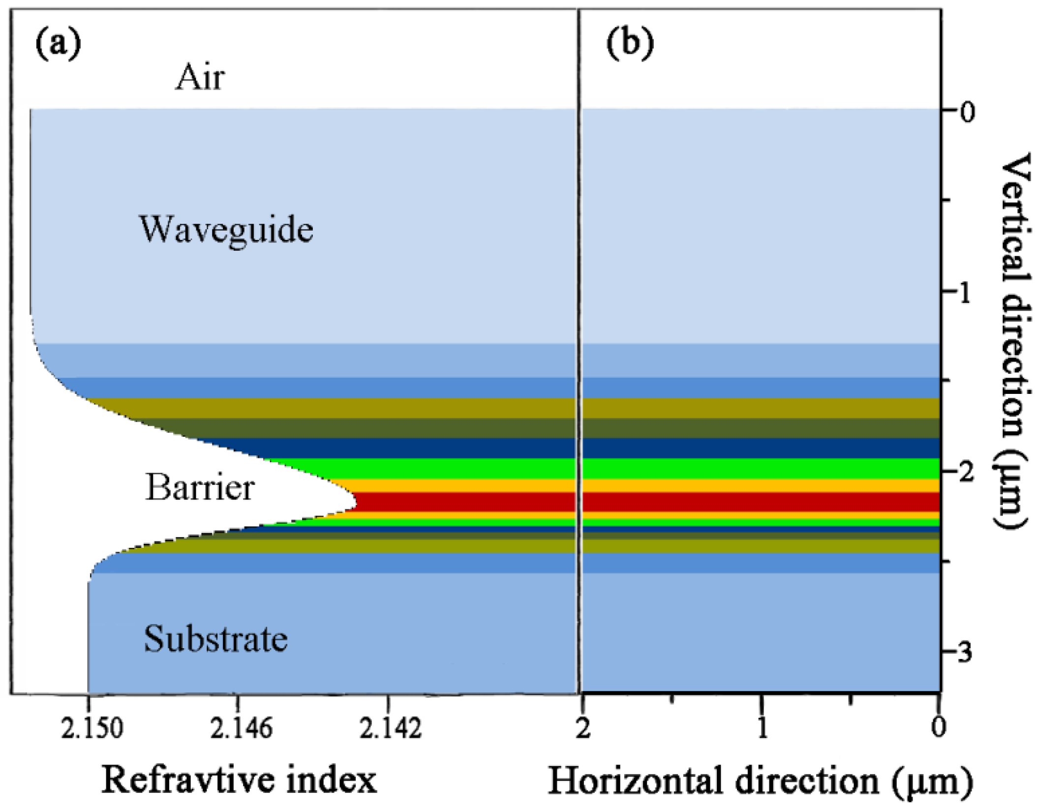
Based on the data of the prism coupling measurement, the refractive index near the crystal surface is reconstructed using a reflectivity calculation method [19], which is testified to be particularly suitable for ion-irradiated materials. The refractive index of the oxygen-irradiated waveguide is depicted in Figure 2. As is shown, the ‘barrier wall’ and ‘enhanced well’ construct the waveguide configuration with a thickness of 2.2 μm. The decrease in refractive index at a depth of 2.2 μm is related to the degree of damage induced from energetic oxygen irradiation. The enhancement of the refractive index in the waveguide region helps to confine the light transmission to some extent. The larger the refractive index contrast between the barrier and the waveguide layer, the stronger the capability of the waveguide to confine the light transmission.
The near-field optical intensity image of the basic TE0 mode in the crystal waveguide is depicted in Figure 3a, which is obtained from the end-face coupling measurement with a wavelength of 632.8 nm. Based on the refractive index distribution in Figure 2, the propagation of light in the crystal waveguide is simulated by applying the beam propagation method [20,21,22], which is famous for its numerical calculation in photonics. The mode intensity distribution is shown in Figure 3b. By comparing the two near-field results, it can be concluded that there is a reasonable consistency between the experimental image and the calculated data. That also means the possibility of designing optical devices, because the refractive index near the surface of the crystal after ion irradiation can be well customized by nondestructive methods.
Lattice modification in the irradiated crystal is investigated by using the high-resolution X-ray diffraction technique. Figure 4 shows the experimental high-resolution X-ray diffraction curves from the crystals before and after irradiation. All three curves show a main diffraction peak at 2θ = 73.5, created by diffraction of the unperturbed region of the crystal. The peak from the irradiated crystals is much broader than that of the pristine crystal, indicating that un-irradiated crystals have better single crystalline properties. The diffraction spectra of irradiated crystals show the asymmetric broadened peak at 2θ < 73.5, which is caused by diffraction of the damaged lattice. It should be noted that there are some satellite peaks in the diffraction spectrum of the irradiated crystal, and its number increases with the increase in the irradiation fluence. These oscillating fringes are on the left side of the main peak, which is characteristic of damage of tensile strain in the oxygen irradiated crystals.
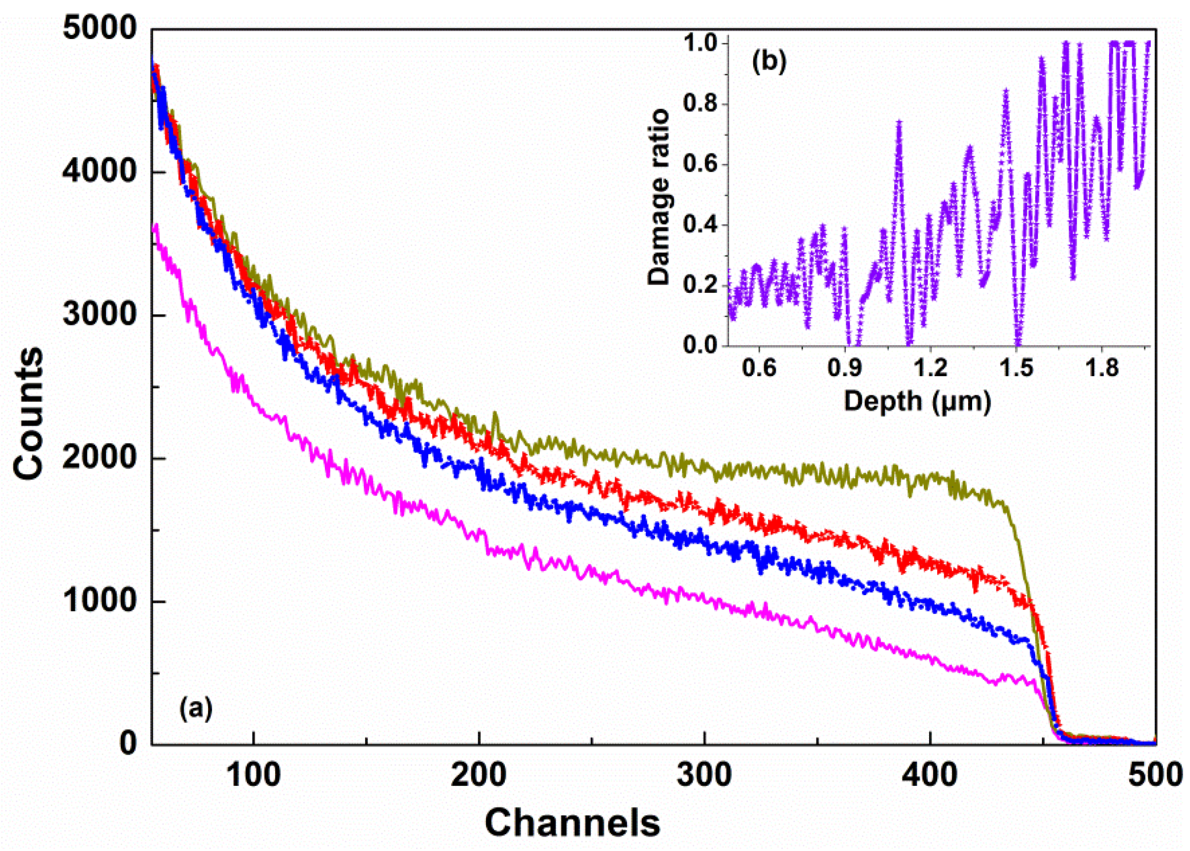
The Rutherford backscattering/channeling spectra of the oxygen ion-irradiated crystals are measured, and the results are shown in Figure 5a. The aligned (magenta line) and random (dark yellow line) spectra of the pristine crystal are also given for comparison. By comparing the aligned spectral heights of the pristine crystal and the irradiated samples, the lattice damage degree of the waveguide region can be obtained. As is shown, the backscattering yield of the irradiated crystal is higher than that of the pristine crystal, and the backscattering yield of the irradiated crystal increases with the increase in oxygen fluence. The aligned spectra of the crystals indicate that the irradiation of energetic oxygen ions causes a certain lattice distortion near the surface region. The depth profiles of the lattice damage near the surface region were extracted from the Rutherford backscattering/channeling spectrum, and the obtained disorder profiles of the sample irradiated with fluence of 1.5 × 10¹⁵ ions/cm2 are shown in Figure 5b. This is achieved by applying a model of multiple scattering dechanneling, which is based on formulas by Rodgers and Feldman [23,24]. As is shown, the lattice damage ratio at the surface of the sample is 20%, and the crystal lattice at the end of the oxygen ion range is seriously damaged due to irradiation, which means that the crystal lattice is completely amorphous.
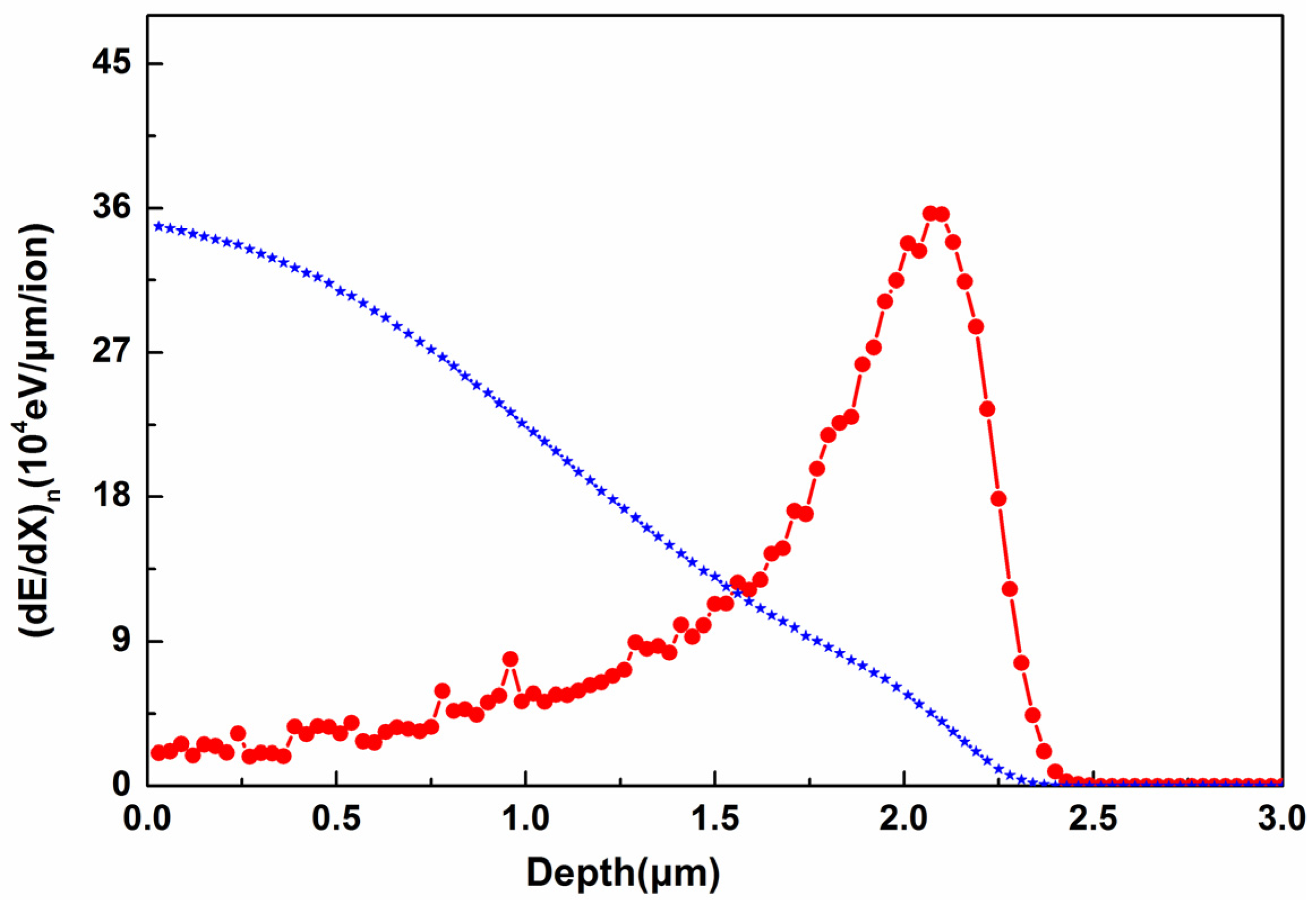
In order to better understand the interaction between oxygen ions and crystals, as well as the formation mechanism of waveguides, the stopping and range of ions in the matter code [25,26] is applied to simulate the process of oxygen irradiation into yttria-stabilized zirconia crystals. Figure 6 exhibits the energy loss of the 4.5 MeV oxygen ions into yttria-stabilized zirconia. As indicated, during the path inside the crystal, most of the energy of incident ions is lost due to electronic ionization, usually accompanied by the formation of color centers. Although it is reported in some reports that ion irradiation in the keV low-energy region usually contributes to lattice disorders caused by elastic collision between energetic ions and the target, electronic ionization may also lead to defects in the irradiation process, especially when energetic ions (close to 5 MeV) are applied [27,28]. While at the end of the ions’ trajectory, the peak value of the nuclear energy loss curve lies at a depth of 2.2 μm below the crystal surface. Nuclear collisions can cause displacement damage, break the crystalline structure and reduce the physical density, resulting in a decrease in the refractive index in this region. The profile of the refractive index is consistent with the simulation results; the consistency indicates the rationality of the waveguide explanation.

4. Conclusions

In conclusion, the waveguide effect is demonstrated in yttria-stabilized zirconia crystal by 4.5 MeV oxygen ion irradiation with different fluences at room temperature. The mode-line spectrum is studied, and the results show that a single mode structure is formed at a fluence of 1.5 × 10¹⁵ ions/cm2. The propagation profiles of the TE-polarized light were investigated in the visible band, and the results have good agreement with the results simulated by the beam propagation method. The Rutherford backscattering/channeling and the high-resolution X-ray diffraction spectra demonstrated that lattice damage occurred during the oxygen ion irradiation. The fabricated yttria-stabilized zirconia waveguide can effectively support the monomode transmission in the near-surface region of the crystal, which is of great significance for the application of integrated optical and optoelectronic devices.

Author Contributions

X.M. originally conceived the idea and wrote the manuscript. X.M. and Z.W. carried out the experiments. X.M. and Y.Z. carried out the simulations. All authors have read and agreed to the published version of the manuscript.

Funding

This research was funded by the National Natural Science Foundation of China (Grant Nos. 11905159) and the Natural Science Foundation of Tianjin City (Grant Nos. 19JCYBJC17000).

Institutional Review Board Statement

Not applicable.

Informed Consent Statement

Not applicable.

Data Availability Statement

Data sharing not applicable.

Conflicts of Interest

The authors declare no conflict of interest.

References

  1. Vazquez, G.V.; Desirena, H.; De la Rosa, E.; Flores-Romero, E.; Marquez, H.; Rickards, J.; Trejo-Luna, R. Upconversion emission in a carbon-implanted Yb:YAG planar waveguide. Opt. Commun. 2012, 285, 5531–5534. [Google Scholar] [CrossRef]
  2. Tervonen, A.; West, B.R.; Honkanen, S. Ion-exchanged glass waveguide technology: A review. Opt. Eng. 2011, 50, 071107. [Google Scholar]
  3. Zhang, F.X.; Velisa, G.; Xue, H.; Sellami, N.; Trautmann, C.; Zhang, Y.; Weber, W.J. Ion irradiation induced strain and structural changes in LiTaO3 perovskite. J. Phys. Condens. Matter 2021, 33, 185402. [Google Scholar] [CrossRef]
  4. Sellami, N.; Crespillo, M.L.; Xue, H.; Zhang, Y.; Weber, W.J. Role of atomic-level defects and electronic energy loss on amorphization in LiNbO3 single crystals. J. Phys. D Appl. Phys. 2017, 50, 325103. [Google Scholar] [CrossRef]
  5. Garcia, J.A.; Rodriguez, R.J. Ion implantation techniques for nonelectronic applications. Vacuum 2011, 85, 1125–1129. [Google Scholar] [CrossRef]
  6. Liu, T.; Kong, W.; Qiao, M.; Cheng, Y. Maintain Raman property in ZnS single crystal waveguide formed by multi-energy He ion implantation at 633 nm. Results Phys. 2018, 11, 822–825. [Google Scholar] [CrossRef]
  7. Ming, X.; Lu, F.; Yin, J.; Chen, M.; Zhang, S.; Zhao, J.; Liu, X.; Ma, Y.; Liu, X. Waveguide effect in ZnO crystal by He+ ions implantation: Analysis of optical confinement from implant-induced lattice damage. Opt. Commun. 2012, 285, 1225–1228. [Google Scholar] [CrossRef]
  8. Botzakaki, M.A.; Xanthopoulos, N.; Makarona, E.; Tsamis, C.; Kennou, S.; Ladas, S.; Georga, S.N.; Krontiras, C.A. ALD deposited ZrO2 ultrathin layers on Si and Ge substrates: A multiple technique characterization. Microelectron. Eng. 2013, 112, 208–212. [Google Scholar] [CrossRef]
  9. Park, B.; Lee, Y.; Oh, I.; Noh, W.; Gatineau, S.; Kim, H. Structural and electrical properties of Ge-doped ZrO2 thin films grown by atomic layer deposition for high-k dielectrics. J. Mater. Sci. 2018, 53, 15237–15245. [Google Scholar] [CrossRef]
  10. Fan, W.; Wang, Z.Z.; Bai, Y.; Che, J.W.; Wang, R.J.; Ma, F.; Tao, W.Z.; Liang, G.Y. Improved properties of scandia and yttria co-doped zirconia as a potential thermal barrier material for high temperature applications. J. Eur. Ceram. Soc. 2018, 38, 4502–4511. [Google Scholar] [CrossRef]
  11. Lo, D.; Shi, L.; Wang, J.; Zhang, G.X. Zirconia and zirconia-organically modified silicate distributed feedback waveguide lasers tunable in the visible. Appl. Phys. Lett. 2002, 81, 2707. [Google Scholar] [CrossRef]
  12. Ye, C.; Wang, J.; Shi, L.; Lo, D. Polarization and threshold energy variation of distributed feedback lasing of oxazine dye in zirzonia waveguides and in solutions. Appl. Phys. B Lasers Opt. 2004, 78, 189–194. [Google Scholar] [CrossRef]
  13. Sorek, Y.; Zevin, M.; Reisfeld, R.; Hurvits, T.; Ruschin, S. Zirconia and zirconia-ORMOSIL planar waveguides prepared at room temperature. Chem. Mater. 1997, 9, 670–676. [Google Scholar] [CrossRef]
  14. Chauhan, V.; Gupta, T.; Koratkar, N.; Kumar, R. Studies of the electronic excitation modifications induced by SHI of Au ions in RF sputtered ZrO2 thin films. Mat. Sci. Semicon. Proc. 2018, 88, 262–272. [Google Scholar] [CrossRef]
  15. Liu, L.; Maeda, K.; Onda, T.; Chen, Z. Microstructure and improved mechanical properties of Al2O3/Ba-β-Al2O3/ZrO2 composites with YSZ addition. J. Eur. Ceram. Soc. 2018, 38, 5113–5121. [Google Scholar] [CrossRef]
  16. Chen, F.; Wang, J. LDS dye-doped zirconia-organically modified silicate distributed feedback planar waveguide lasers. Appl. Phys. B 2013, 113, 259–264. [Google Scholar] [CrossRef]
  17. Ye, C.; Wong, K.Y.; He, Y.; Wang, X. Distributed feedback sol-gel zirconia waveguide lasers based on surface relief gratings. Opt. Express 2007, 15, 936–944. [Google Scholar] [CrossRef]
  18. Ulrich, R.; Torge, R. Measurement of thin film parameters with a prism coupler. Appl. Opt. 1973, 12, 2901–2908. [Google Scholar] [CrossRef] [Green Version]
  19. Chandler, P.J.; Lama, F.L. A new approach to the determination of planar waveguide profiles by means of a non-stationary mode index calculation. Opt. Acta 1986, 33, 127–143. [Google Scholar] [CrossRef]
  20. Chung, Y.C.; Dagli, N. An assessment of finite difference beam propagation method. IEEE J. Quantum Electron. 1990, 26, 1335–1339. [Google Scholar] [CrossRef]
  21. Huang, W.P.; Xu, C.L. Simulation of three-dimensional optical waveguides by a full-vector beam propagation method. IEEE J. Quantum Electron. 1993, 29, 2639–2649. [Google Scholar] [CrossRef]
  22. Hadley, G.R. Transparent boundary condition for the beam propagation method. IEEE J. Quantum Electron. 1992, 28, 363–370. [Google Scholar] [CrossRef] [Green Version]
  23. Sato, K.; Fujino, Y.; Yamaguchi, S.; Naramoto, H.; Ozawa, K. Ion channeling studies of C+ irradiated TiC single crystals. Nucl. Instrum. Methods Phys. Res. B 1990, 47, 421–426. [Google Scholar] [CrossRef]
  24. Feldman, L.C.; Rodgers, J.M. Depth profiles of the lattice disorder resulting from ion bombardment of silicon single crystals. J. Appl. Phys. 1970, 41, 3776–3782. [Google Scholar] [CrossRef]
  25. Ziegler, J.F. Interactions of Ions with Matter. Available online: www.srim.org (accessed on 1 August 2021).
  26. Ziegler, J.F.; Ziegler, M.D.; Biersack, J.P. SRIM–The stopping and range of ions in matter. Nucl. Instrum. Methods Phys. Res. Sect. B 2010, 268, 1818–1823. [Google Scholar] [CrossRef] [Green Version]
  27. Olivares, J.; García-Navarro, A.; Méndez, A.; Agulló-López, F.; García, G. Novel optical waveguides by in-depth controlled electronic damage with swift ions. Nucl. Instrum. Methods Phys. Res. B 2007, 257, 765–770. [Google Scholar] [CrossRef]
  28. Peithmann, K.; Zamani-meymian, M.R.; Haaks, M.; Maier, K. Fabrication of embedded waveguides in lithiumniobate crystals by radiation damage. Appl. Phys. B 2006, 82, 419–422. [Google Scholar] [CrossRef]
Figure 1. Mode-line spectrum of crystal waveguide irradiated by energetic oxygen ions.
Applsci 11 10750 g001
Figure 2. (a) 1D and (b) 2D refractive index profiles near the crystal surface after oxygen ion irradiation.
Applsci 11 10750 g002
Figure 3. The near-field optical intensity profile of the waveguide irradiated with fluence of 1.5 × 10¹⁵ ions/cm2: (a) experimental result collected by CCD camera; (b) simulation results by applying the beam propagation method.
Applsci 11 10750 g003
Figure 4. High-resolution X-ray diffraction curves of (a) pristine crystal, (b) crystal irradiated with fluence of 5 × 10¹⁴ ions/cm2, (c) crystal with fluence of 1.5 × 10¹⁵ ions/cm2.
Applsci 11 10750 g004
Figure 5. (a) Aligned and random spectra for yttria-stabilized zirconia crystals before and after oxygen irradiation. (b) The disorder profile near surface region were extracted from the Rutherford backscattering/channeling spectrum.
Applsci 11 10750 g005
Figure 6. Electronic energy loss (blue star, divided by 10) and nuclear energy loss (red ball) of 4.5 KeV oxygen ion irradiation.
Applsci 11 10750 g006
Publisher’s Note: MDPI stays neutral with regard to jurisdictional claims in published maps and institutional affiliations.