Abstract
A method to analyze the variation of the jamming power received by an unmanned aerial vehicle (UAV) receiver according to the change in the attitude of the small UAV is presented. The main interest of the study is in the variation of the polarization loss factor (PLF) in the UAV jamming link due to attitude change, which may be caused by the wind or intended movement. The attitude change is modeled by a combination of three successive rotations using roll, pitch, and yaw, which are defined as UAV rotations. The proposed method is applied to a jamming link, where a small UAV with an omnidirectional antenna is jammed by a jammer antenna on the ground. The method is applied to a plane ground and over a simulated terrain. The variation of the PLF according to the change of UAV attitude may be higher than the generally expected PLF at locations where the height difference between the UAV and the jammer is large, and near the locations where the jammer is located close to the vertical plane containing the rotation axis when the attitude change is represented by one rotation.
1. Introduction
Recently, small unmanned aerial vehicles (UAVs) have frequently been used for military and civilian applications [1,2,3,4]. The risks involving small UAVs are problematic in both areas because the application can monitor private activities, collect data, and even directly attack [5,6].
In order to neutralize the risk from small UAVs, RF jamming is frequently considered [7,8,9]. The jammer-to-signal power ratio (JSR) can be used as an indicator to show the effectiveness of the jamming [10]. In a UAV jamming link, the JSR can be defined as the ratio of the received power by the UAV receiver of jamming signal to the signal for mission performance. Both signals can be estimated by the Friis transmission equation by providing such parameters as the gain, polarization loss factor (PLF), and positions of the transmitter antenna and the receiver antenna, transmission power, and frequencies [11].
Unlike many other larger aircraft, small UAVs suffer greatly from unpredictable attitude changes induced by the wind, which then cause changes in the gain and polarization of the antenna mounted on the UAV as the directions to other antennas are varied. When considering the effectiveness of jamming, it is frequently assumed that a fixed value of the polarization loss exists for all configurations [12], or polarization loss is not taken into account in the jamming link [13,14,15]. However, polarization loss can have a significant impact on the jamming link.
In this paper, we propose a method to analyze the variation of the jamming power received by the UAV receiver in the UAV jamming link due to UAV attitude changes. The antenna is assumed to be fixed to the UAV body, and thus, the antenna radiation characteristics can be described in reference to the local coordinates of the UAV body. The attitude change is modeled by three successive rotations using roll, pitch, and yaw which are defined as UAV rotations.
2. Variation in Jamming Power Reception Due to the Attitude Change
Figure 1 shows a UAV jammed by a ground jammer in the line of sight. The radiation pattern of the UAV antenna is shown to change according to the attitude change. When the jamming power is applied to the jammer, the jamming power received by the UAV receiver can be expressed by the following equation:
where is the wavelength, is the distance between the UAV and the jammer; and are, respectively, the antenna gain and polarization in a given direction; and are, respectively, the elevation and azimuth representing the angular location of the other antenna in reference to the local coordinate system of the antenna; is the reflection coefficient due to the impedance mismatching between the feed line and the antenna; is the characteristic impedance in free space; is the electric field component of the antenna in a given direction in a far field; and the subscripts J and A, respectively, represent the quantities associated with the jammer antenna and the UAV antenna. The antenna gain can be determined by the following equation:
where is the power accepted by the antenna , is the applied power to the feed line connected to the antenna, and is the electric field intensity of the antenna in the far-field. The electric field intensity can be defined by the following equation:
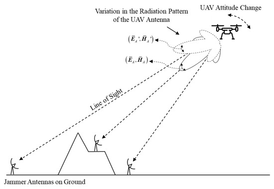
Figure 1.
Geometry of the UAV jammed by ground jammers considering the effect of the change in UAV attitude on the UAV jamming link.
The electric field component can be expressed by the following equation:
where and are, respectively, the E-field component of and components based on the antenna local coordinate system, whose data can be obtained through a simulation or a measurement of the electric field pattern of the antenna when the antenna operates in the Tx mode; and are the unit vectors expressed in the spherical coordinates in reference to the local coordinate system of the antenna; and , , and are, respectively, the electric field components of the antenna for the and components, which can be obtained through coordinate system transformation. , , and are, respectively, the unit vectors along the axis representing the global coordinate system. The unit vectors (i.e., , , and ) are calculated by the following equation:
where , , and are, respectively, the unit vectors along the axis representing the local-coordinate system of the antenna. The unit vectors (i.e., , , and ) are expressed as:
The electric field components of the antenna for the components in the far field, , , and , can be calculated by the following equation:
, , and are varied as the attitude of the antenna changes in a given direction in reference to the global coordinate system. To determine the parameters, the angular locations and need to be determined first.
For the local coordinate system of the UAV antenna and the vector from the UAV to the jammer in Figure 2, the angular location for the jammer and is determined as follows:
where is the projection of on the plane containing and . The angular location and for the UAV in reference to the local coordinate system of the jammer antenna can be determined in a similar manner. However, if a UAV attitude change occurs, the radiation pattern of the UAV antenna changes in reference to the global coordinate system. The attitude change can be described as three successive rotations [16,17]. The attitude change is modeled by the following equation:
where , , and are the unit vectors representing the local coordinate system of the UAV antenna affected by the attitude change; , , and are, respectively, the rotation transformation matrix of roll, pitch, and yaw; , , and are, respectively, the rotation axes of roll, pitch, and yaw; , , and are, respectively, the rotation angles of roll, pitch, and yaw. Equation (8) is for the case where the antenna attitude change is in the order of roll, pitch, and yaw. If the rotation order changes, the equation can be changed. The rotation transformation matrix , for example, is defined as:
where . The angular location and for the jammer in reference to can be determined by the following equation:
where is the projection of on the plane containing and . The jamming power received by the UAV receiver affected by the attitude change can be calculated by following equation:
where , , and are, respectively, the gain, the polarization, and the electric field component of the UAV antenna for the jammer in reference to . The amount of change in jamming power received by the UAV receiver due to the attitude change can be calculated by the following equation:
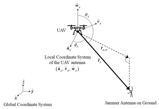
Figure 2.
The elevation and azimuth location and for the jammer antenna on the ground in reference to the local coordinate system of the UAV antenna .
It includes both the gain variation and the PLF variation. The PLF variation is frequently ignored [12,13,14,15]. However, the PLF variation can have a significant impact on the jamming link. The variation of the PLF due to the attitude change is represented by the following equation:
In the next section, as an example of the attitude change, we analyze the received jamming power in the UAV jamming link if the UAV antenna has a roll rotation.
3. Analysis of the Received Jamming Power in the UAV Jamming Link Due to the Attitude Change
Figure 3 shows the configuration of a small hovering UAV jammed by a jammer on the ground. The positions of the UAV and jammers are defined in the global coordinate system. The UAV is at height from the origin of the global coordinate system and the jammer is at on the ground. In Figure 3, is the vector from the UAV position to the jammer position and is the elevation angle, which is the included angle between the vector and the horizontal plane at the jammer position.
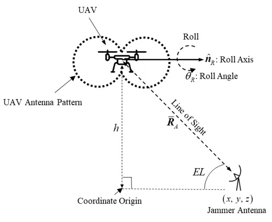
Figure 3.
Configuration of the small hovering UAV jammed by a jammer on the ground considering the UAV roll (UAV height: , the roll axis: , the roll angle: ).
If both the jammer antenna and the UAV antenna use an omnidirectional vertically polarized antenna, there is no polarization loss in the UAV jamming link, regardless of the height of the UAV and the position of the jammer. However, if the UAV attitude changes, polarization loss may occur.
As an example of UAV attitude change, we considered UAV roll rotation. The UAV roll rotation has a roll axis of and a roll angle of . When the UAV has a constant height and the jammer is on a plane ground, the variation in the received jamming power due to the UAV roll according to the position of the jammer is shown as a contour and shadow map in Figure 4. The area where the UAV antenna gain in the initial attitude is less than 10 dB compared to the maximum gain is indicated by a dotted line and is called a blind zone.
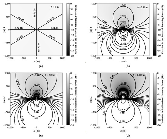
Figure 4.
Contour and shadow map of the variation in received jamming power due to the UAV roll (, ); where the UAV height is at (a) 0 m, (b) 250 m, (c) 500 m, and (d) 1000 m, and the jammer is on plane ground.
Figure 4a shows the case when the height of the UAV and the jammer are the same. The line with is perpendicular to the axis of rotation. Thus, there is no PLF variation. On the other hand, on the line with , there is no gain variation. Thus, the power variation shown in −0.76 dB and −0.54 dB in and are due only to gain and PLF variations, respectively. In other locations, the power variations are contributed both from the gain and PLF variations.
Figure 4b–d shows the cases when the height of the UAV and the jammer are different. As in Figure 4a, the power variations in are due only to gain variation. In other locations, the power variations are contributed both from the gain and PLF variations. The variation is overall increased as the height difference increases because the jammer location is closer to the null direction of the omnidirectional antenna, where the gain and polarization variation is large.
In order to show the contributions of the gain and PLF variations separately, they are separately shown in Figure 5 and Figure 6. It can be seen that Figure 4 and Figure 5 are almost the same because the gain variation is dominant in most locations. However, near the rotation axis, the two sets of figures are notably different because of the contributions from the PLF variation. The contribution from the PLF variation is shown in Figure 6. As shown in Figure 6a, when the height of the UAV and the jammer are the same, the maximum variation in the PLF of −0.54 dB occurs in , which is the axis of rotation. As shown in Figure 6b–d, the larger the height difference between the two antennas, the greater the variation in the PLF, because the jammer location is closer to the null direction of the omnidirectional antenna.
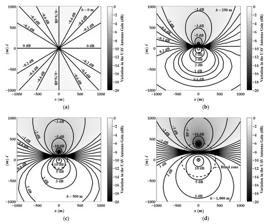
Figure 5.
Contour and shadow map of the variation in the UAV antenna gain to the UAV roll (, ); where the UAV height is at (a) 0 m, (b) 250 m, (c) 500 m, and (d) 1000 m, and the jammer is on plane ground.
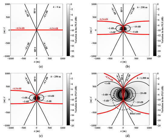
Figure 6.
Contour and shadow map of the variation in the PLF to the UAV roll (, ) where the UAV height is at (a) 0 m, (b) 250 m, (c) 500 m, and (d) 1000 m, and the jammer is on plane ground.
When the UAV has a constant height and the jammer is over a simulated terrain, the variation in the PLF due to the UAV roll according to the position of the jammer is shown as a contour and a shadow map, as shown in Figure 7. The UAV roll rotation has a roll axis of and a roll angle of . The simulated terrain has a distribution from 0 m to about 700 m and is displayed on the map as thin lines at 50 m height intervals.
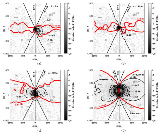
Figure 7.
Contour and shadow map of the variation in the PLF due to the UAV roll (, ) where the UAV height is at (a) 0 m, (b) 250 m, (c) 500 m, (d) 1000 m, and the jammer height is over a simulated terrain.
As shown in Figure 7a, when the UAV is at a height of 0 m, it can have a higher PLF when the jammer is located on a high terrain. As shown in Figure 7d, when the UAV is located at a height of 1000 m, it may have a high PLF when the jammer is located on a low terrain rather than a high terrain. Our analysis revealed that the greater the height difference between the UAV and the jammer, the higher the PLF can be for the terrain close to the vertical plane containing the axis of rotation.
The method was applied to a small hovering UAV jamming application by a ground jammer. The method was applied to a plane ground and over a simulated terrain. It is normally expected that there is a PLF of . However, when the UAV is at a high altitude and the jammer antenna is near the vertical plane containing the rotation axis, the PLF tends to be larger than expected.
In practice, the roll axis and the roll angle may be unknown values. When a hovering UAV remains horizontal, the roll axis of the UAV is defined in the horizontal plane and can be modeled as follows:
where is the azimuthal angle of . The roll angle is a time-varying quantity. If the roll angle has a uniform distribution probability from to , the expected value of the PLF in the UAV jamming link can be expressed as the following equation:
where is the elevation angle from the jammer to the UAV in reference to the global coordinate system. can be calculated as:
where is the height difference between the jammer and the UAV, and is the distance between the jammer and the UAV. The expected values of PLF according to and are shown in Figure 8. The larger the maximum roll angle and the larger the elevation angle , the greater the expected polarization loss .
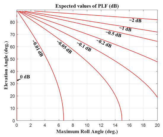
Figure 8.
Expected values of the PLF in UAV jamming link according to the and .
4. Conclusions
There is no polarization loss in the UAV jamming link if the UAV receiver and jammer use omnidirectional vertically polarized antennas. However, if an UAV attitude change occurs due to the wind or an intended movement, there is polarization loss in the UAV jamming link.
This paper presented a method to analyze the variation of the jamming power received by the UAV receiver in the UAV jamming link due to an UAV attitude change. The attitude change was modeled by the three coordinate rotations in a sequence of roll, pitch, and yaw.
The proposed method was applied to a small hovering UAV jamming application by a ground jammer. The method was applied to a plane ground and over a simulated terrain. It is normally expected that there is a PLF of in the UAV jamming link if the UAV has a roll rotation with a roll angle of .
However, as a result of analyzing the polarization loss in the UAV jamming link through the modeling of attitude change, we demonstrated that the PLF due to the attitude change is greater than expected in such circumstances as when the UAV is at a high altitude and the jammer antenna on the ground is near the vertical plane containing the axis of rotation. Therefore, the PLF in the jamming power received by the UAV due to the attitude change must be considered for the UAV jamming link.
Author Contributions
K.K. (Kiin Kim) and K.K. (Kangwook Kim) analyzed the algorithm and derived the mathematical formulation. C.L. and H.K. checked the simulation results and corrected the manuscript. K.K. (Kiin Kim) and K.K. (Kangwook Kim) wrote the paper. Supervision, K.P. All authors have read and agreed to the published version of the manuscript.
Funding
This work was supported by Agency for Defense Development, Republic of Korea, under the contract “Modelling and Simulation Based Design and Analysis Technologies for Electronic Warfare Systems”.
Institutional Review Board Statement
Not applicable.
Informed Consent Statement
Not applicable.
Data Availability Statement
Not applicable.
Conflicts of Interest
There is no conflict of interest.
References
- Hoffer, N.V.; Coopmans, C.; Jensen, A.M.; Chen, Y. A Survey and categorization of small low-cost unmanned aerial vehicle system identification. J. Intell. Robot. Syst. 2014, 74, 129–145. [Google Scholar] [CrossRef]
- Ding, W.; Gong, C.; Mosalam, K.M.; Soga, K. Development and application of the integrated sealant test apparatus for sealing gaskets in tunnel segmental joints. Tunn. Undergr. Space Technol. 2017, 63, 54–68. [Google Scholar] [CrossRef]
- Khuwaja, A.A.; Chen, Y.; Zhao, N.; Alouini, M.-S.; Dobbins, P. A survey of channel modeling for UAV communications. IEEE Commun. Surv. Tutor. 2018, 20, 2804–2821. [Google Scholar] [CrossRef] [Green Version]
- Eisenbeiss, H. A mini unmanned aerial vehicle (UAV): System overview and image acquisition. Int. Arch. Photogramm. Remote Sens. Spat. Inf. Sci. 2004, 36, 1–7. [Google Scholar]
- Sathyamoorthy, D. A review of security threats of unmanned aerial vehicles and mitigation steps. J. Def. Secur. 2015, 6, 81–97. [Google Scholar]
- Miasnikov, E. Threat of Terrorism Using Unmanned Aerial Vehicles: Technical Aspects; Center for Arms Control, Energy, and Environmental Studies, Moscow Institute of Physics and Technology: Moscow, Russia, 2005. [Google Scholar]
- Shi, X.; Yang, C.; Xie, W.; Liang, C.; Shi, Z.; Chen, J. Anti-drone system with multiple surveillance technologies: Architecture, implementation, and challenges. IEEE Commun. Mag. 2018, 56, 68–74. [Google Scholar] [CrossRef]
- Pärlin, K.; Alam, M.M.; le Moullec, Y. Jamming of UAV remote control systems using software defined radio. In Proceedings of the 2018 International Conference on Military Communications and Information Systems (ICMCIS), Warsaw, Poland, 22–23 May 2018; pp. 1–6. [Google Scholar] [CrossRef]
- Chamola, V.; Kotesh, P.; Agarwal, A.; Naren; Gupta, N.; Guizani, M. A Comprehensive Review of Unmanned Aerial Vehicle Attacks and Neutralization Techniques. Ad Hoc Netw. 2021, 111, 102324. [Google Scholar] [CrossRef] [PubMed]
- De Martino, A. Introduction to Modern EW Systems; Artech House: Boston, MA, USA, 2018. [Google Scholar]
- Balanis, C.A. Antenna Theory: Analysis and Design; John Wiley & Sons: Hoboken, NJ, USA, 2015. [Google Scholar]
- Jędrusik, P. Efficiency of using active interference dedicated to medium range surveillance radar. In Proceedings of the Radioelectronic Systems Conference 2019, Jachranka, Poland, 11 February 2020; Volume 11442. [Google Scholar] [CrossRef] [Green Version]
- Mpitziopoulos, A.; Gavalas, D. An effective defensive node against jamming attacks in sensor networks. Secur. Commun. Netw. 2009, 2, 145–163. [Google Scholar] [CrossRef]
- Surendra, L.; Shameem, S.; Susmitha, N.; Ram, T.S. Analysis of self-screening jammer parameters with radar equation. Int. J. Eng. Res. Appl. 2014, 4, 205–207. [Google Scholar]
- Park, S.R.; Nam, I.; Noh, S. Modeling and simulation for the investigation of radar responses to electronic attacks in electronic warfare environments. Secur. Commun. Netw. 2018, 2018, 3580536. [Google Scholar] [CrossRef]
- Díaz, E.O. 3D Motion of Rigid Bodies: A Foundation for Robot Dynamics Analysis; Springer: Berlin/Heidelberg, Germany, 2018; Volume 191. [Google Scholar]
- Study on Channel Model for Frequencies from 0.5 to 100 GHz. Document 3rd Generation Partnership Project(3GPP) Technical Report 38.901, Version 16.1.0. December 2019. Available online: portal.3gpp.org/desktopmodules/Specifications/SpecificationDetails.aspx?specificationId=3173 (accessed on 6 September 2021).
Publisher’s Note: MDPI stays neutral with regard to jurisdictional claims in published maps and institutional affiliations. |
© 2021 by the authors. Licensee MDPI, Basel, Switzerland. This article is an open access article distributed under the terms and conditions of the Creative Commons Attribution (CC BY) license (https://creativecommons.org/licenses/by/4.0/).