1. Introduction
With the depletion of shallow coal resources, China has entered the mining stage of kilometer-deep coal resources. During hoisting in the kilometer-deep coal mine, the hoisting rope (twisted by spiral strands and steel wires) is always in the mine spray water (the acid spray water of deep coal mine in southern China) and subjected to dynamic tensile, bending, and torsional loads [
1], which induces the tension–torsion fretting fatigue of inclined crossed steel wires in acid solution. The tension–torsion fretting fatigue life of steel wire consists of crack initiation and propagation lives. In fretting fatigue, most of the fatigue life of steel wire is spent propagating the crack since the fatigue crack initiates in the very early stage of the fatigue life (the initiation of fatigue crack occurred approximately at 10–20% of the total life) [
2]. Coupled roles of tensile fatigue, torsional fatigue, and fretting wear during tension–torsion fretting fatigue cause the multiaxial stress states at the fretting contact region. As is known, the contact load and torsion angle greatly affect multiaxial stress distributions, shear stiffnesses, dimensions, and damage mechanisms at the fretting contact region [
3], which restricts crack propagation characteristics of steel wires during tension–torsion fretting fatigue in acid solution. Meanwhile, the crack propagation characteristics of steel wires under coupled roles of fretting wear and electrochemical corrosion directly result in the wire fracture and cross-section area loss of hoisting rope, which causes the scrapping of hoisting rope and even malignant safety accidents of wellbore destruction and personnel death [
4].Therefore, it is significant to investigate effects of contact load and torsion angle on crack propagation behaviors of inclined crossed steel wires during tension–torsion fretting fatigue in acid solution in order to reveal the failure mechanism and to ensure the service safety and reliability of hoisting rope in the kilometer-deep coal mine.
Considering the fretting fatigue and tension–torsion fretting fatigue of perpendicularly crossed wires, Cruzado et al. [
5] analyzed the effect of wear on the reduction of fatigue life of steel wire. They proposed that Manson’s method and medians method gave lives closer to those obtained from fretting wear tests in steel wires, and the life reduction is attributed to the increase in normal contact load. Ahmad et al. [
6] calculated stress distributions and relative displacements of strand wires under fretting fatigue condition. They found that the relative movement occurred at the boundaries of the contact region in the presence of friction, and the existence of slip was due to different displacements of outer and central wires. Llavori et al. [
7] conducted preliminary studies for understanding the effect of the crossing angle between wires on tangential force measurement and proposed the non-Coulomb behavior during fretting fatigue in the case of a high crossing angle. Wang et al. [
1] explored the effect of electrolyte solution on the tribo-corrosion-fatigue mechanisms of perpendicularly crossed wires. They found that the decrease order of maximum wear depth and increase order of fatigue life were as follows: air, acid, neutral and alkaline electrolyte solutions, and deionized water. Meanwhile, it was found that the degree of electrochemical corrosion and maximum crack depth of fatigue wire were the largest in the acid electrolyte solution. Takeuchi et al. [
2] studied the behavior of fatigue crack growth in the fretting-corrosion fatigue of high-tensile roping steel in air and seawater and found that the method of removing the electrochemical component was very promising for the prevention of fretting fatigue failure in seawater. Li [
8] explored multiaxial fretting fatigue behaviors of steel wires and found larger damage during tension–torsion fretting fatigue as compared to tension–tension fretting fatigue and torsional fretting. Zhang et al. [
9] investigated fretting fatigue behaviors of steel wires contact interfaces under different crossing angles, and found that lower contact load, total wear volume and friction coefficient, and larger fretting fatigue life were induced at a crossing angle of 18 degrees as compared to the case of a crossing angle of 90 degrees. However, the effects of contact load and torsion angle on crack propagation behaviors of inclined crossed steel wires during tension–torsion fretting fatigue in acid solution through combined analyses of wear and electrochemical corrosion have not been reported.
2. Experimental
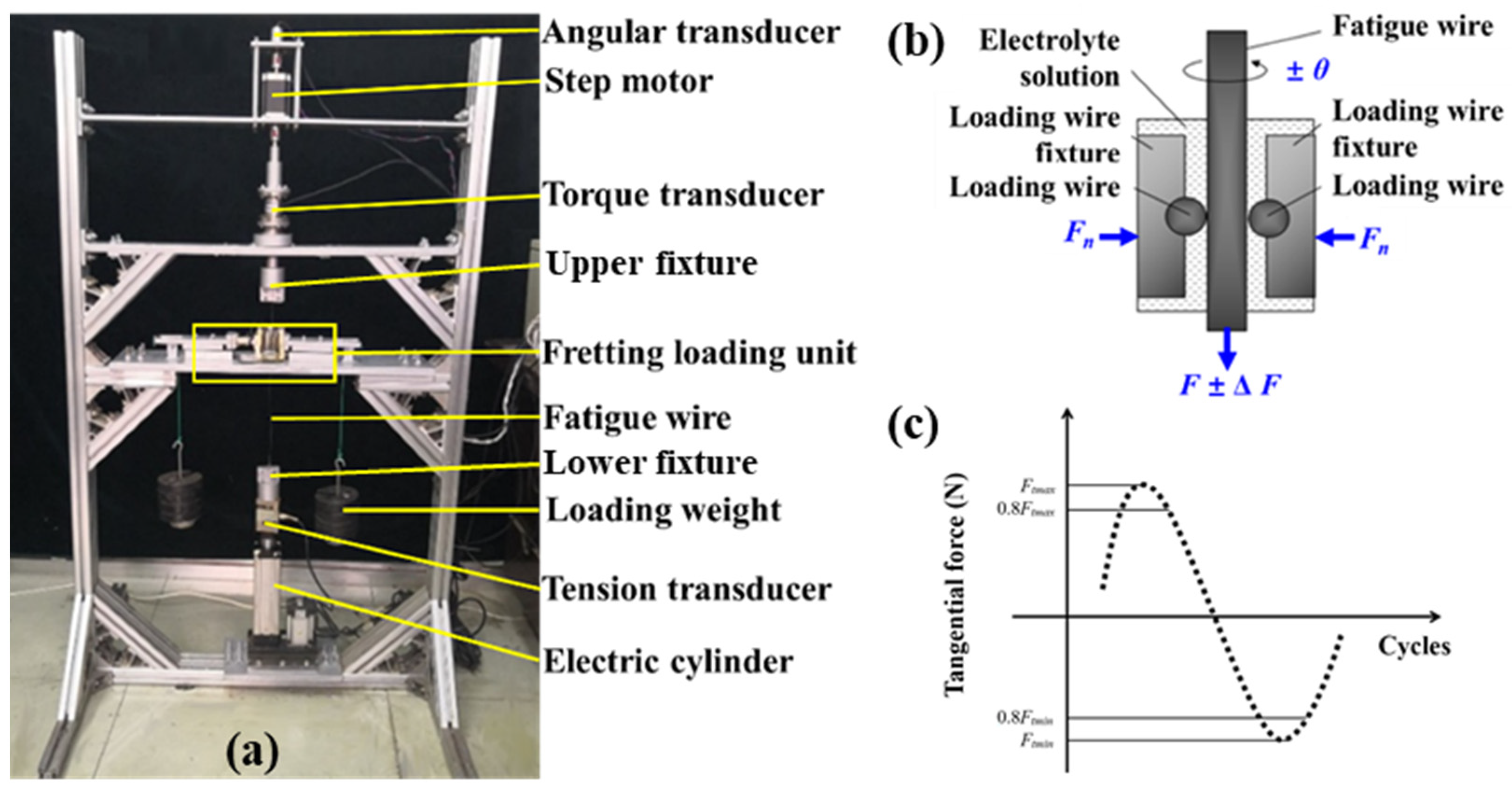
Tension–torsion fretting fatigue tests of inclined crossed steel wires in acid solution were conducted using the test rig as depicted in
Figure 1. Before the test, the initial tension was applied to fatigue wire using the servo electric cylinder. The loading weight was employed to apply constant contact load between fatigue wire and loading wires. The dynamic sealant was used to seal the circular hole of container through which the fatigue wire passes, and the electrolyte solution was added to the container afterwards. Moreover, the servo electric cylinder was employed to apply the axial fatigue load to fatigue wire and thereby causes the axial deformation of fatigue wire and micron relative displacement between steel wires. Meanwhile, the reversible stepping motor was used to apply the torsional fatigue of fatigue wire. Finally, the tension torsion fretting fatigue in the acid solution was realized. During the test, the tension transducer, torque transducer, angle transducer, and tangential force transducer were employed to monitor the axial load, torque, torsion angle, and friction force, respectively. The constant contact load can be obtained by the loading weight. The friction coefficient is supposed to be the ratio of average friction force in the range of 0.8
Ftmax–
Ftmax (peak value of friction force,
Figure 1c) to contact load in each fatigue cycle [
1,
4,
8]. The displacement of servo electric cylinder was recorded to reveal the deformation of fatigue wire (Δ
l) and, thereby, to obtain the relative displacement between steel wires in the fretting zone (Δ
x) through the scaling down method, i.e., Δ
x = Δ
l·
s/
l). In the equation,
s represents the distance between the upper fixture and fretting contact region, and
l indicates the length of fatigue wire between upper and lower fixtures. The scanning electron microscope and white light interference microscope were employed to analyze morphologies and depth profiles of wear scars of fatigue wires, respectively. The three-dimensional X-ray tomographic micro-imaging system is used to reveal crack propagation characteristics of fatigue wires after the tests [
1,
10]. Tafel polarization curves and impedance spectra were measured using an electrochemical analyzer to reveal the corrosion degree and corrosion resistance of fatigue wire. Three repeated tests were conducted for each series of testing parameters.
According to the chemical composition of mine water found in deep coal mines in southern China, the acid electrolyte solution was prepared with the deionized water, CaSO
4, MgSO
4, Na
2SO
4, HCl, and K
2SO
4 in the lab, and its pH value was 3.5 [
1]. The chemical compositions of acid electrolyte solution are 1.3 mg/L H
+, 11.7 mg/L K
+, 92.4 mg/L Na
+, 676.6 mg/L Ca
+, 364.7 mg/L Mg
2+, 28.4 mg/L Cl
−, and 3283.8 mg/L SO
42−. The carbon structural steel wire in this study has the diameter of 1 mm. The mass compositions of material elements of steel wire are 98.71% Fe, 0.87% C, 0.39% Mn, 0.02% Si, and 0.01% Ni.
The testing parameters are as follows [
1,
4]: crossing angle between steel wires of 26°, tensile stress ratio of 0.55 and stress amplitude of 203 MPa, torsion angles of ±1.5°, ±2.0° and ±2.5°, contact loads of 30 N–50 N, relative displacement between steel wires of ±100 μm at the fretting contact region, and fretting frequency of 5 Hz. Before the tests, the steel wire is polished with 800 mesh fine sandpaper and scrubbed with alcohol to remove surface pollutants.
3. Effect of Contact Load on Crack Propagation Characteristics of Inclined Crossed Steel Wires in Acid Solution
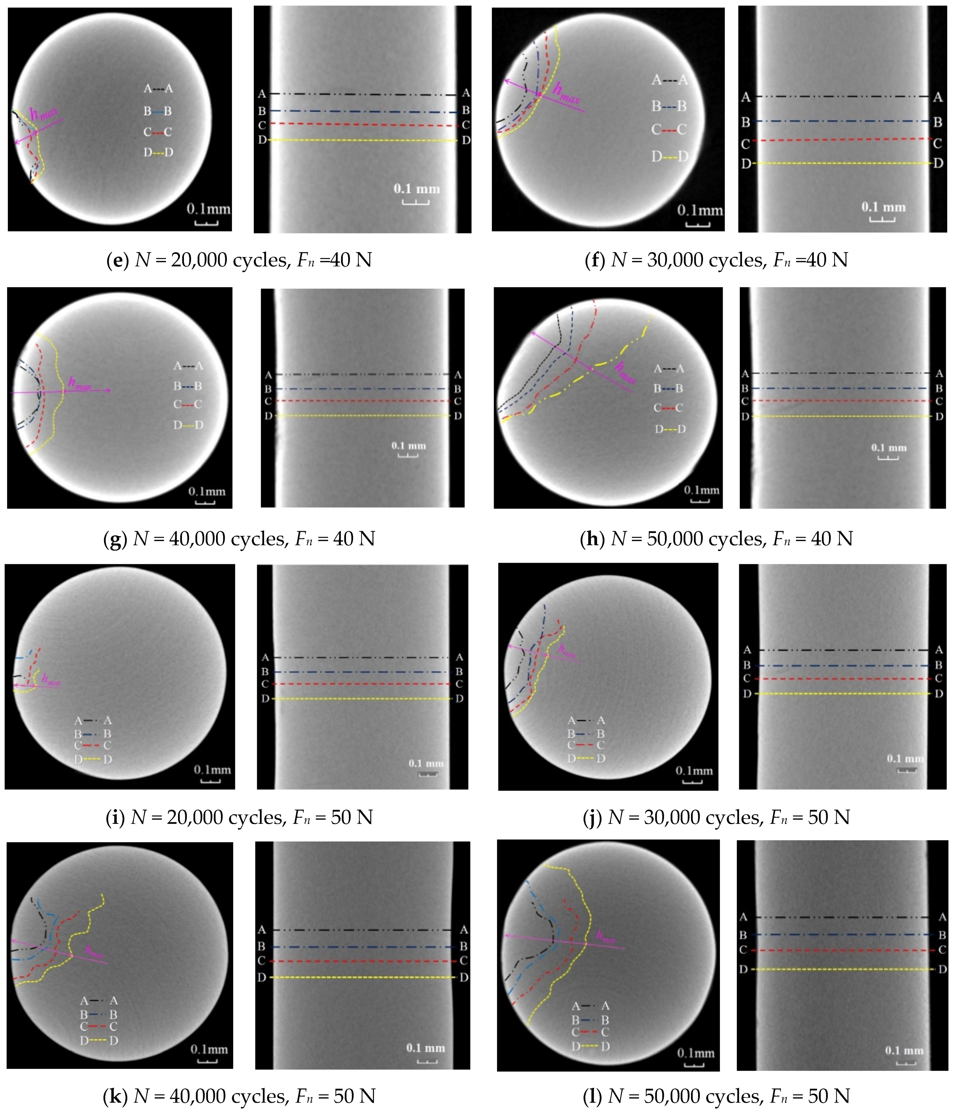
Figure 2 and
Figure 3 show the crack initiation from the middle or trailing edge of wear scar and crack propagation with the direction inclined to fatigue wire axis in cases of all contact loads. The crack profiles of different cross-sections at the wear scar always exhibited irregular arcs around the wear scar. A change in cross-section from A-A to D-D causes the gradual change of crack profile from arc shape to the approximately straight line and the increase in the maximum crack depth. The maximum crack depth
hmax increases with increasing fatigue cycles, and an increase in contact load causes the increase in
hmax at the same fatigue cycles indicating the increased crack propagation rate. During the test, coupled effects of tensile fatigue, torsional fatigue, and fretting wear induce the multiaxial stress concentration state at the wear scar and the non-proportional loading mode [
11]. The multiaxial fatigue crack always initiates at the maximum shear stress plane [
12,
13], which indicates the crack initiation at the wear scar and propagation along the direction inclined to the axis of fatigue wire. As the maximum crack depth of fatigue wire increases, the crack profile moves away from wire surface, propagates towards the axis of fatigue wire, and gradually tends to be straight. Increases in fatigue cycles and contact load both cause increases in the average tangential force between steel wires (
Figure 4 and
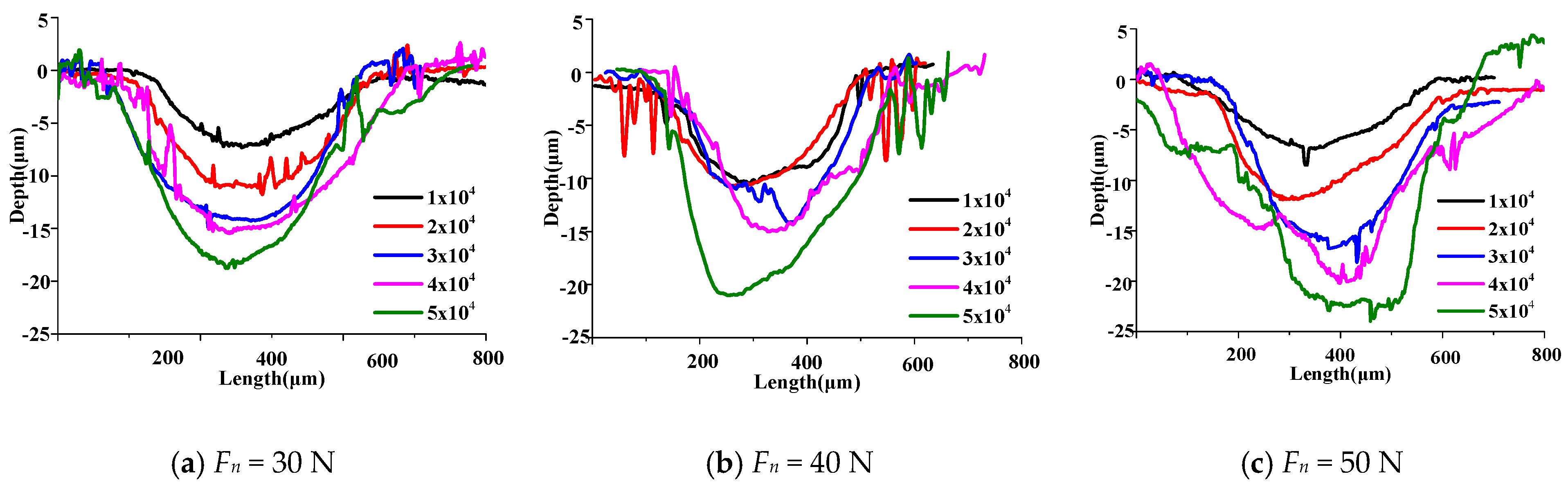
Figure 5) and wear depth of fatigue wire (
Figure 6) as well as the accelerated electrochemical corrosion damage (
Figure 7) and surface damage (
Figure 8), which causes the increased crack depth and propagation rate of fatigue wire.
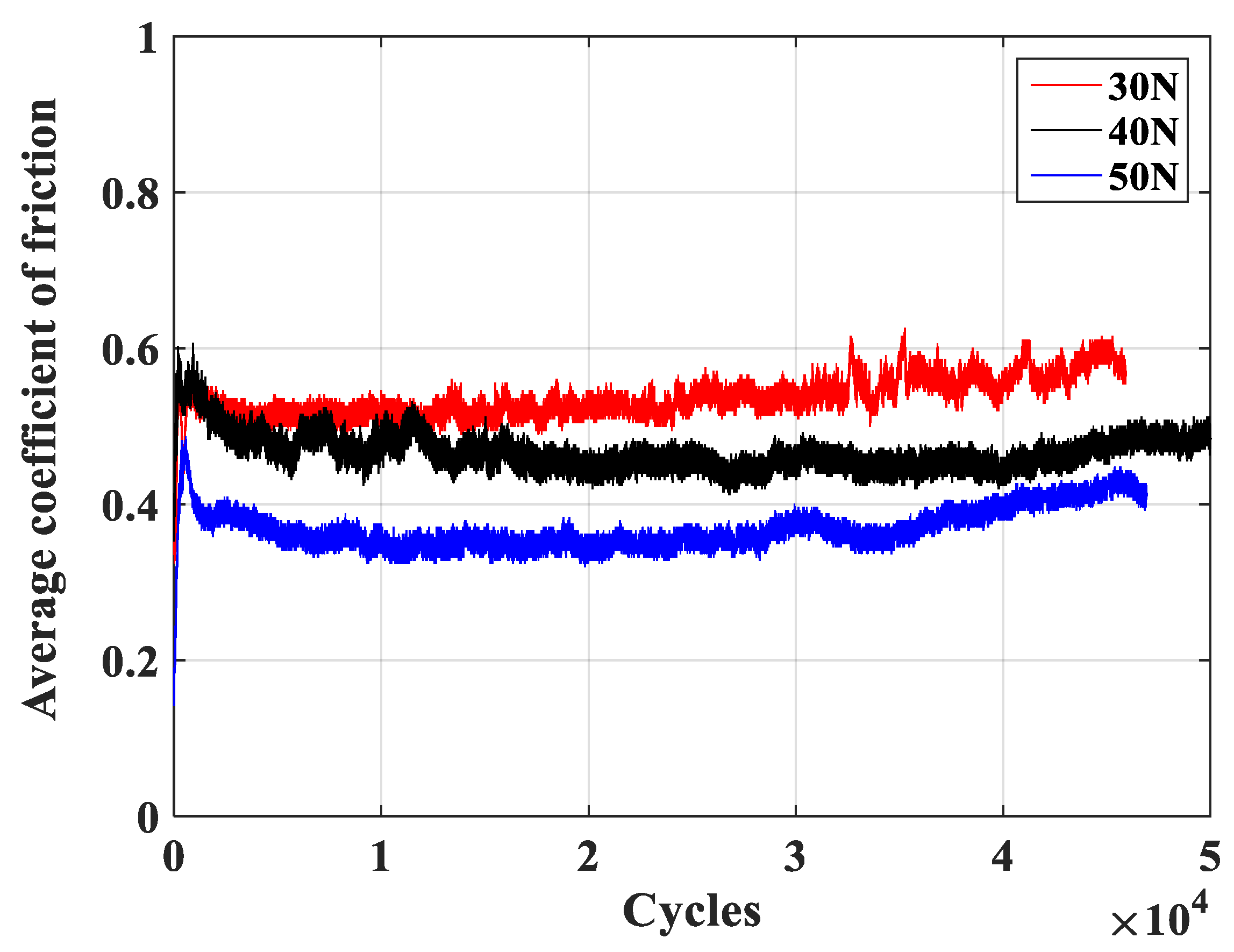
Figure 4 shows that the friction coefficient presents the fluctuating change with increasing fatigue cycles in cases of different contact loads. The average friction coefficients at the stabilized stage at contact loads of 30 N, 40 N, and 50 N are 0.58, 0.49, and 0.41, respectively, and average tangential forces are 17.4 N, 19.6 N, and 20.5 N, respectively. Therefore, the average tangential force between wires increases with increasing fatigue cycles and contact load. It is clearly seen from
Figure 5a–c that all
Ft-
D hysteresis loops exhibit the parallelogram shapes in all cases, which indicates the gross slip states between contacting wires [
1,
4]. As the contact load increases, the relative slip between contacting wires presents the overall decrease trend.
Figure 5d–f shows the obvious hysteresis phenomenon between torque and torsion angle. Meanwhile, the openness of the
T-θ hysteresis loop increases with increasing torsion angle, which indicates the larger relative slip along the torsional direction and larger torsional damage [
8].
Figure 6 shows that the wear profile and wear depth of fatigue wires both increase with increasing fatigue cycles and contact load, respectively.
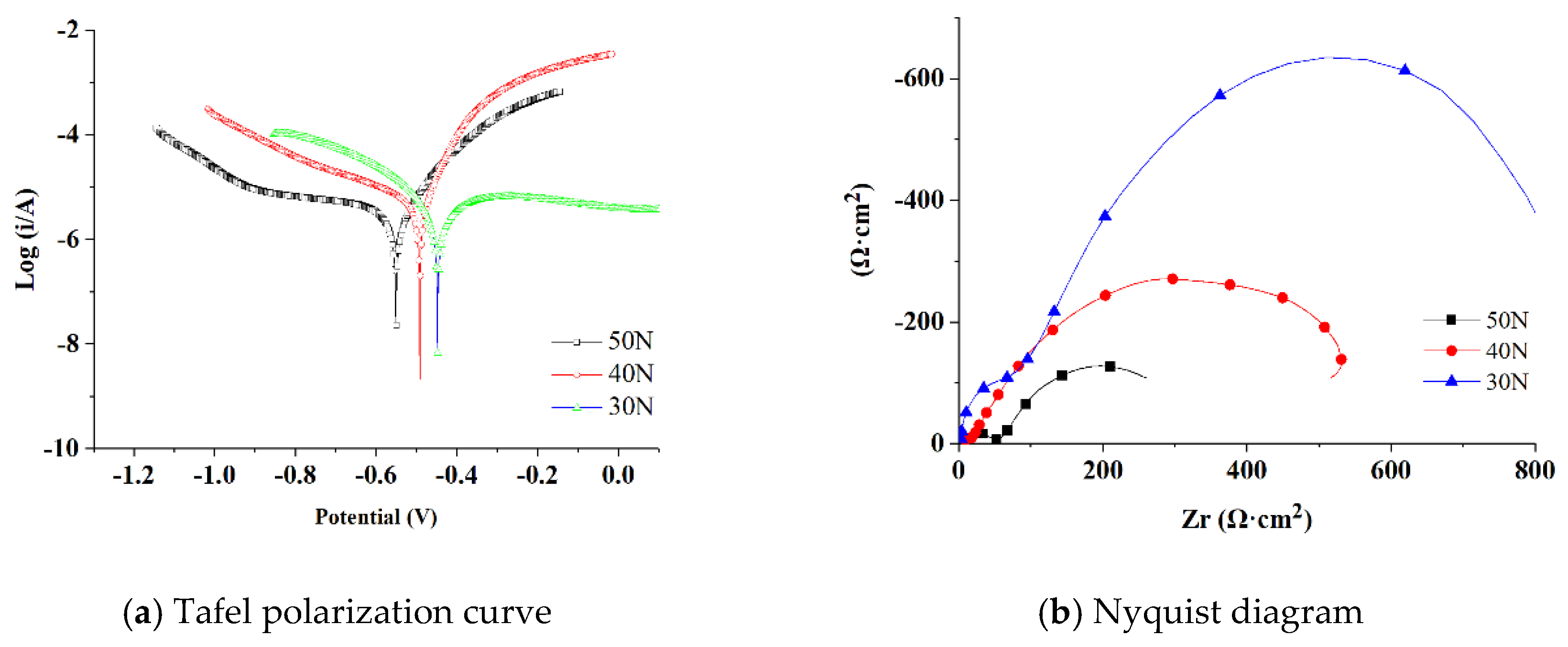
Figure 7a shows that the intersection point of the anode and cathode polarization curves of fatigue wire exhibits the free corrosion potential, indicating difficulties in losing electrons and corrosion tendency [
14]. The free corrosion potentials of fatigue wires move negatively by 116 mV and 70 mV as the contact load changes from 30 N to 50 N and from 40 N to 50 N, respectively, which indicates that an increase in contact load causes the increase in the corrosion tendency of fatigue wires. It is clearly seen from
Figure 7b that the Nyquist diagram presents the capacitive reactance arc in all cases, and the arc radius decreases with increasing contact load indicating the decrease in the corrosion resistance of fatigue wire. Therefore, fatigue wire shows the most serious electrochemical corrosion at a contact load of 50 N.
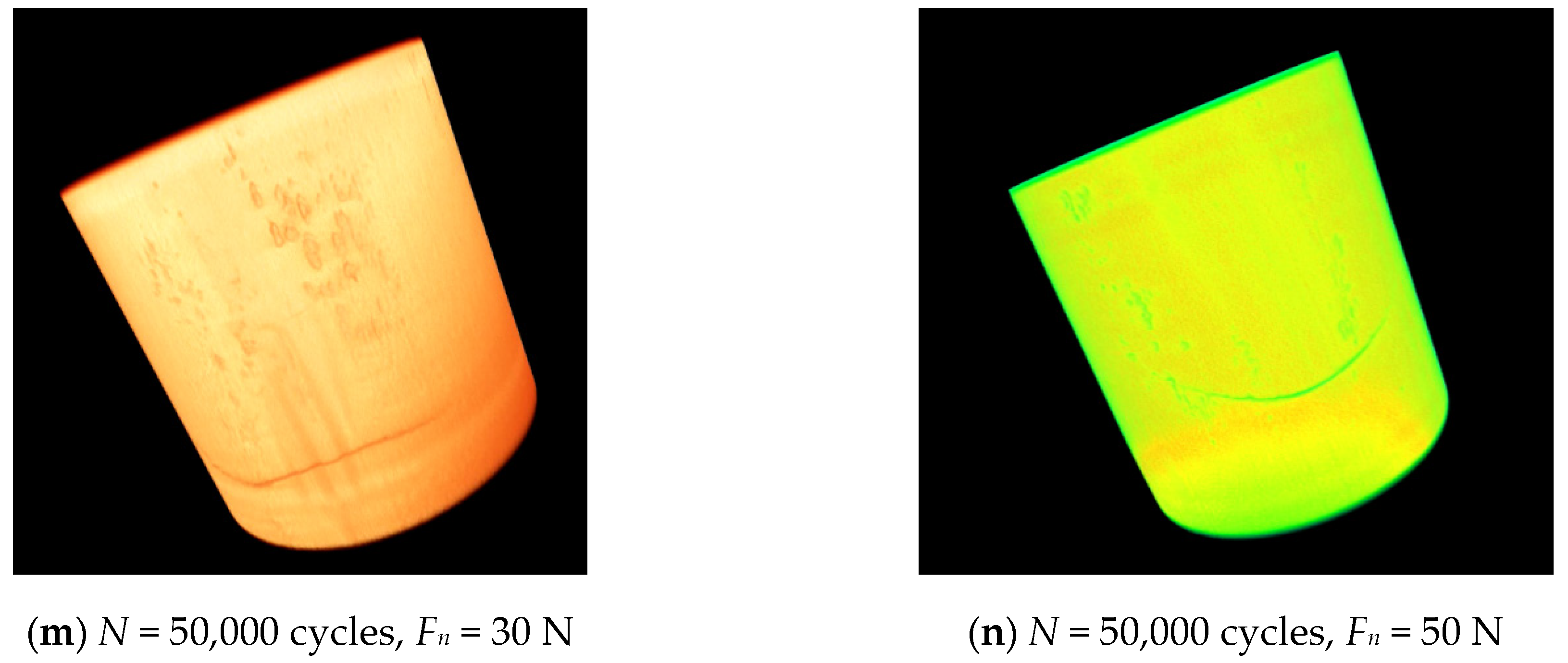
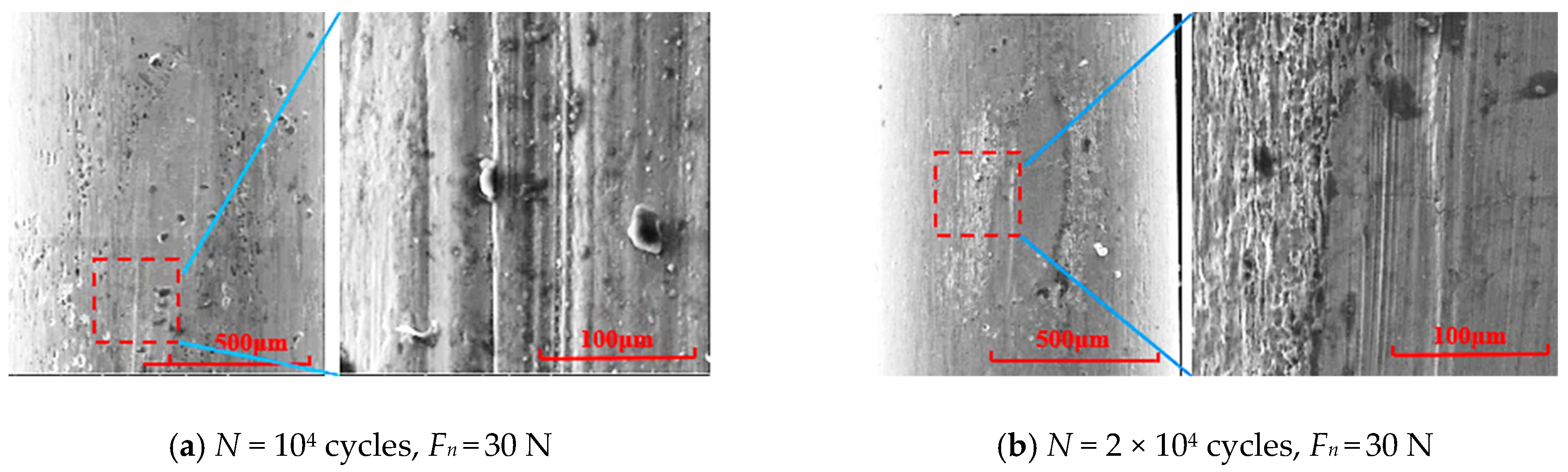
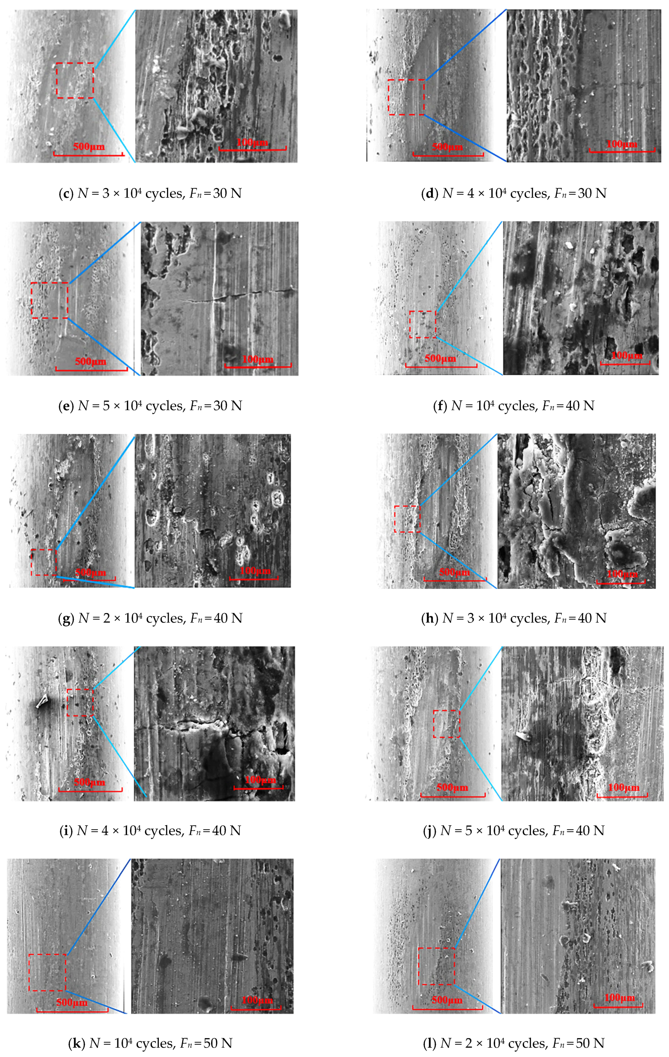
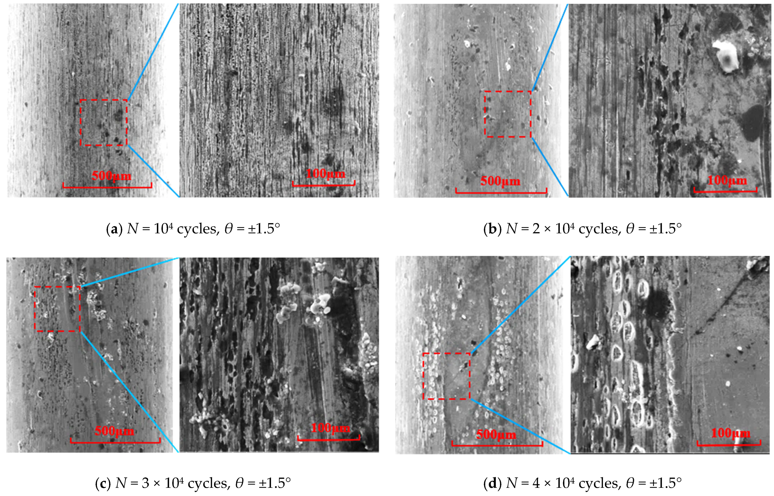
Figure 8a–e shows wear mechanisms of abrasive wear, fatigue wear, and corrosion wear. Dimensions of cracks at the wear scar increases with increasing fatigue cycles, and the ploughing and electrochemical corrosion both accelerate.
Figure 8f–j shows wear mechanisms of abrasive wear, adhesive wear, fatigue wear, and corrosion wear. The number and dimensions of cracks at the wear scar both increase, and the small pits change to large-area pits as the fatigue cycles increase.
Figure 8k–o shows wear mechanisms of abrasive wear, adhesive wear, fatigue wear, and corrosion wear. Increases in fatigue cycles cause enhanced ploughing effect of wear scar of fatigue wire, increased dimensions of cracks across the wear scar, accelerated material adhesion phenomenon, and the change of many small pits to large-area rough pits. Therefore, the surface damage of fatigue wire increases with increasing contact load.
It is clearly observed from
Figure 3 that fitting equations of fitting curves of crack propagation depth evolutions of fatigue wires in cases of different contact loads are described as Equations (1)–(3). The fitting curves show the goodness of fit of 0.967, 0.958, and 0.942 at contact loads of 30 N, 40 N, and 50 N, respectively, which indicates the good fitting consistency. It is clearly seen that the crack propagation evolution curve of fatigue wire exhibits the initial, stable, and rapid crack propagation regions [
15,
16], respectively. The initial crack propagation region exhibits the small crack depth of fatigue wire. The crack depth and propagation rate of fatigue wire both increase with increasing fatigue cycles in the case of stable crack propagation region. In the rapid crack propagation region, the crack propagation rate increases rapidly, the residual strength of fatigue wire decreases sharply, and the number fatigue cycles is close to the fatigue life of fatigue wire. The fatigue wires exhibit a larger difference between the maximum crack propagation depths of fatigue wires in cases of different contact loads at stable and rapid crack propagation regions as compared the initial crack propagation region.
Table 1 shows that the fatigue life of fatigue wires decreases with increasing contact load.
4. Effect of Torsion Angle on Crack Propagation Characteristics of Inclined Crossed Steel Wires in Acid Solution
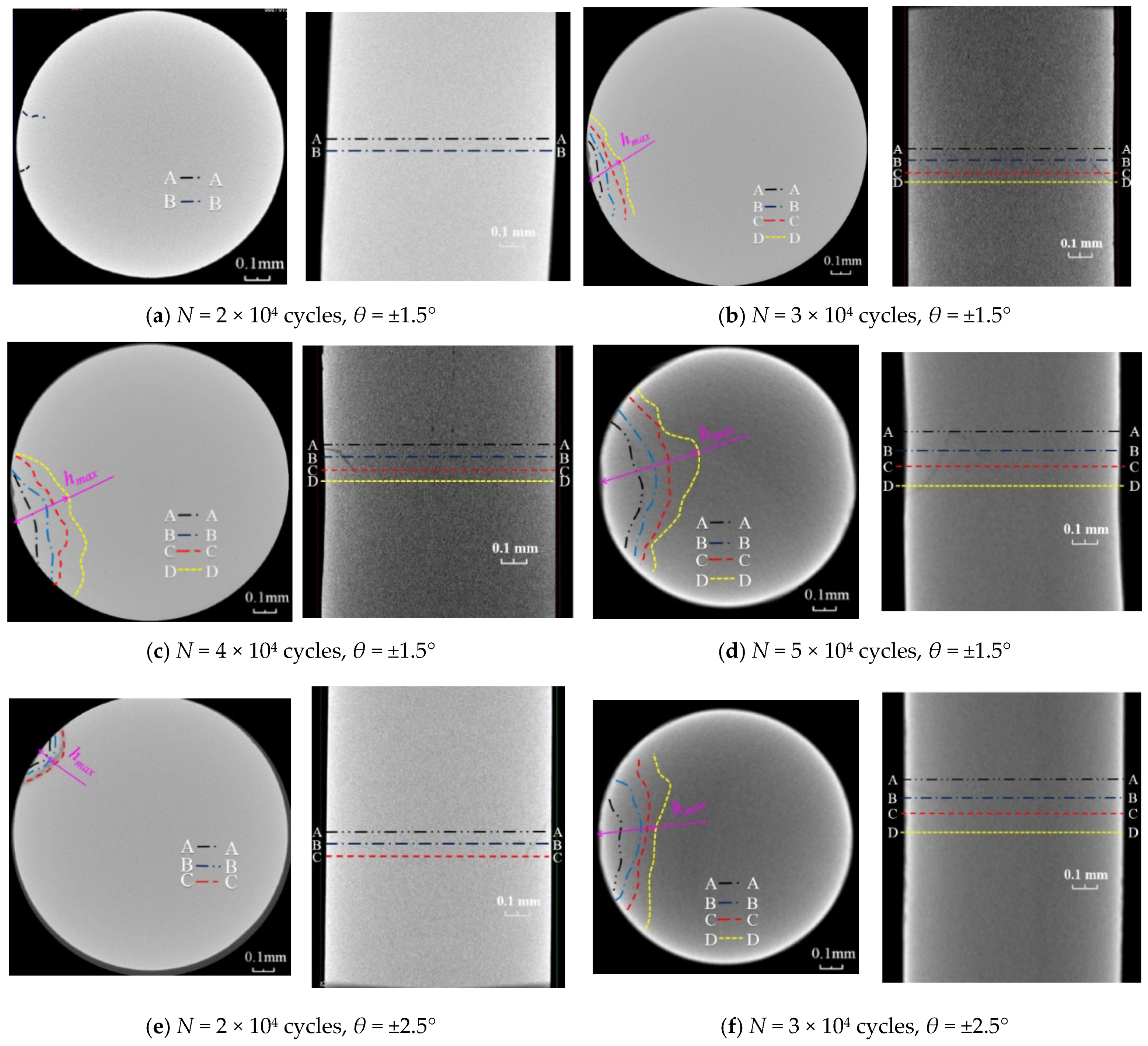
Figure 9 and
Figure 10 show the crack initiation of fatigue wires from the wear scar and propagation along the direction inclined to the axis of fatigue wire in all cases. The crack profiles are always irregular arcs around the wear scar in all cases. The crack propagation depth and rate of fatigue wire both increase with increasing fatigue cycles and torsion angle, attributed to the increased average tangential force between steel wires (
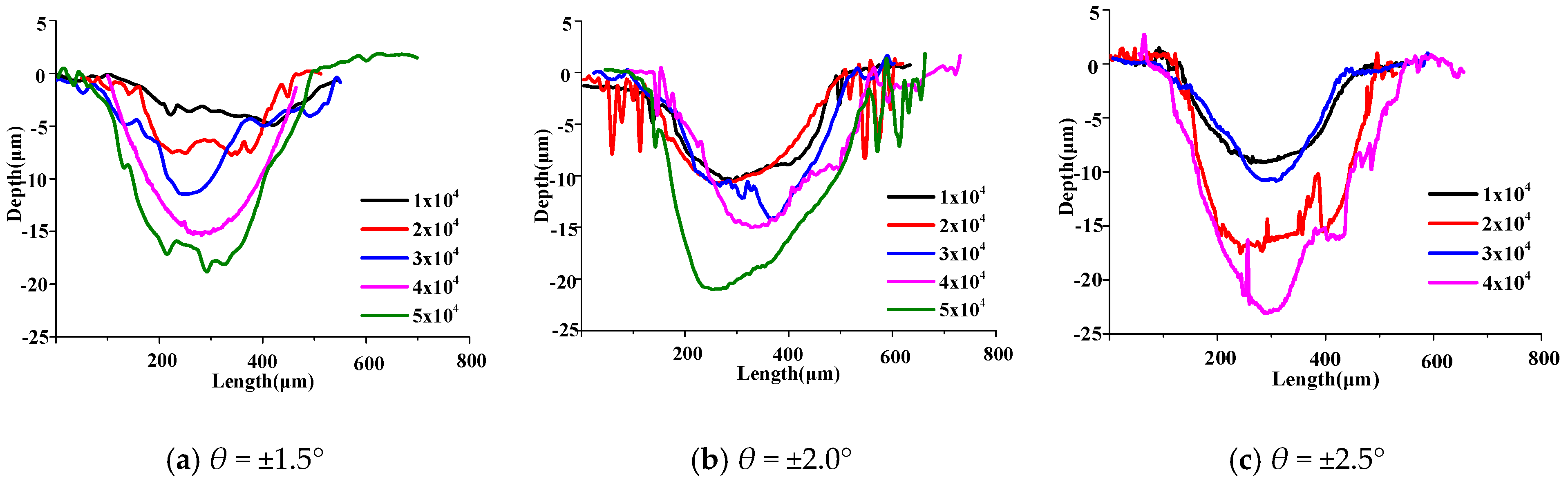
Figure 11) and wear depth (
Figure 12) as well as accelerations of electrochemical corrosion damage (
Figure 13) and surface damage (
Figure 14).
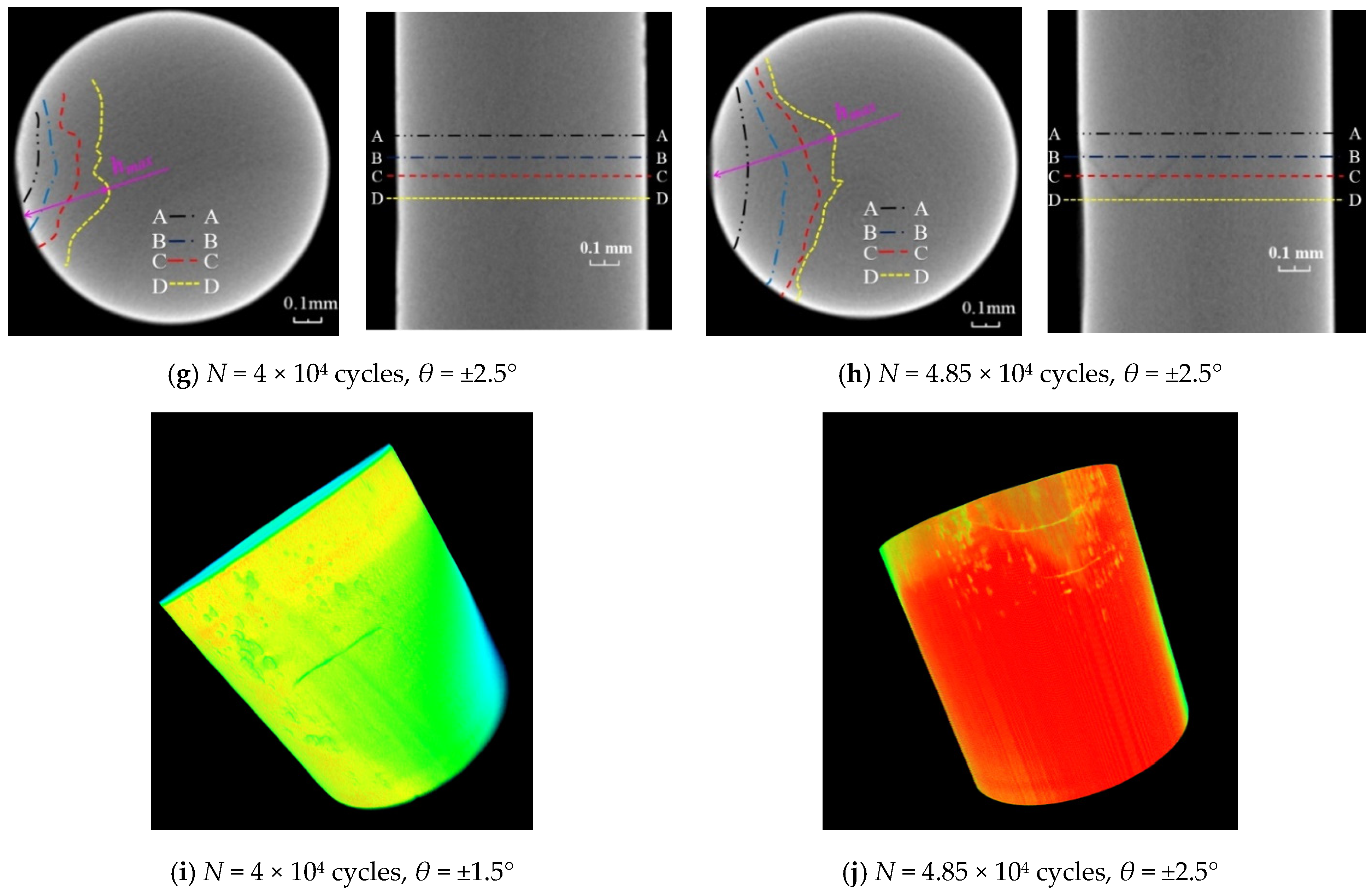
Figure 10 shows the fitting curve of crack propagation depth evolution of fatigue wire in cases of different torsion angles, and fitting equations are described as Equations (2), (4) and (5). The fitting curves show the goodness of fit of 0.987, 0.958, and 0.933 at torsion angles of ±1.5°, ±2.0°, and ±2.5°, respectively, which indicates the good fitting consistency. The fatigue wires exhibit a large difference between the maximum crack propagation depths of fatigue wires and the large crack propagation rate at large fatigue cycles.
Table 1 shows that the fatigue life of fatigue wire decreases with increasing torsion angle.
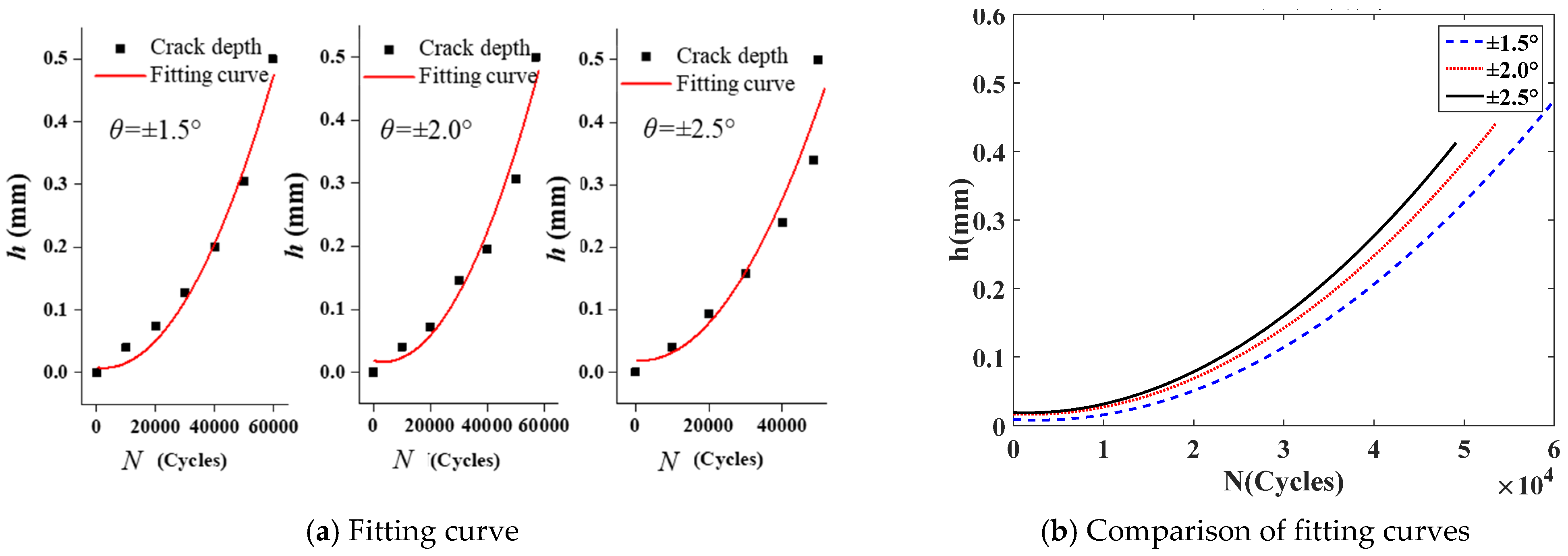
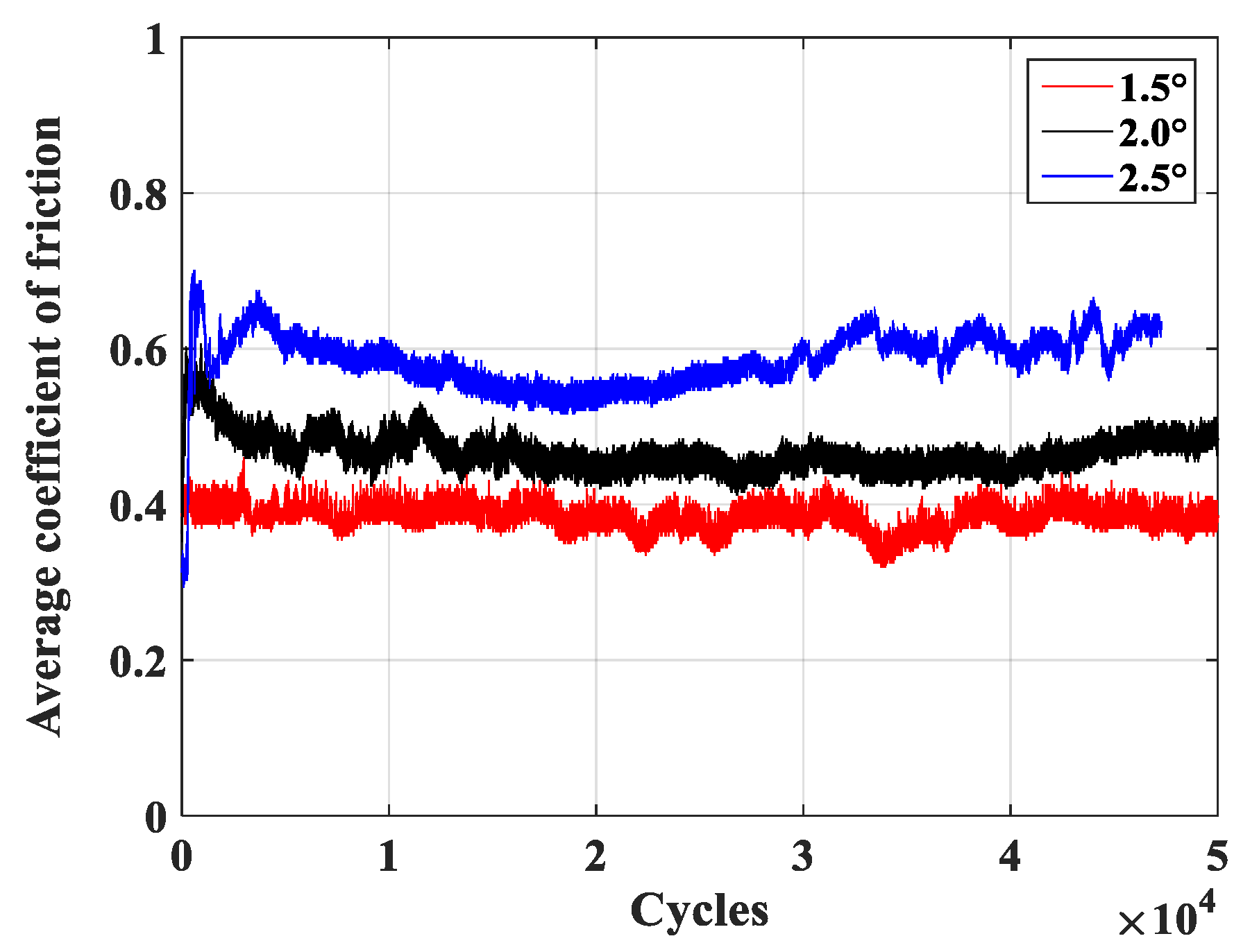
Figure 11 shows the fluctuating changes of the friction coefficient as fatigue cycles increase in cases of different torsion angles. When torsion angles are ±1.5°, ±2.0°, and ±2.5°, average friction coefficients at the stabilized stage are 0.39, 0.49, and 0.6, respectively, and average tangential forces are 17.4 N, 19.6 N, and 20.5 N, respectively, which indicate increased average tangential forces with increasing fatigue cycles and torsion angle, respectively.
Figure 12 shows increased wear profile and depth with increasing fatigue cycles in cases of different torsion angles. As the torsion angle increases, the wear depth of fatigue wire increases at the same fatigue cycles.
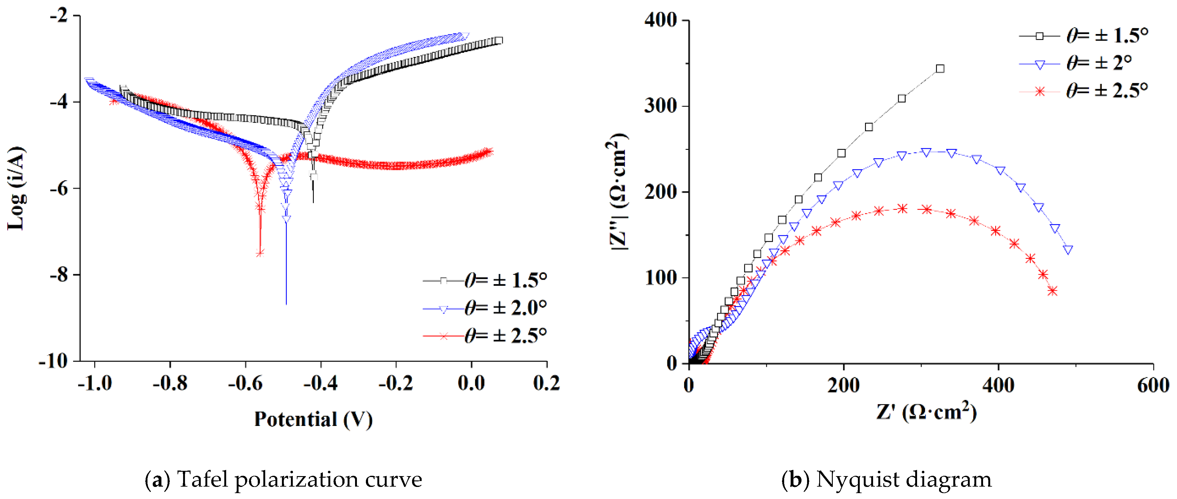
Figure 13a shows that the free corrosion potential of fatigue wire at the torsion angle of ±2.5° moves negatively by 143 mV and 70 mV as compared to torsion angles of ±1.5° and ±2.0°, respectively, which demonstrates the increased corrosion tendency of fatigue wire with increasing torsion angle.
Figure 13b shows the decreased arc radius with increasing torsion angle, revealing the decreased corrosion resistance of fatigue wire. Therefore, the fatigue wire exhibits the most severe electrochemical corrosion damage at the torsion angle of ±2.5°.
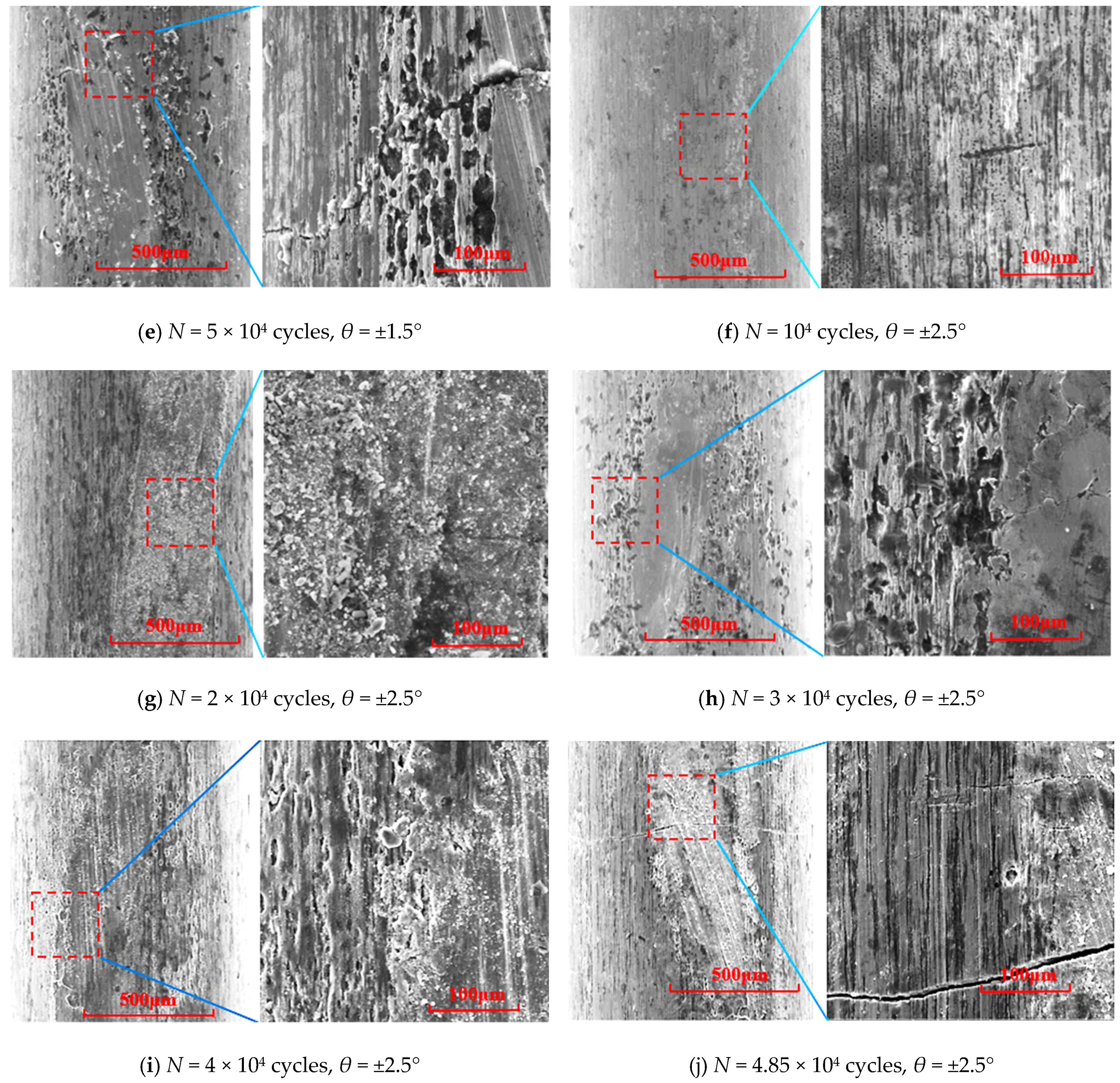
Figure 14a–e shows wear mechanisms of abrasive wear, adhesive wear, fatigue wear, and corrosion wear. As fatigue cycles increase, the dimension of fatigue cracks of fatigue wire increase, the electrochemical corrosion damage accelerates, and the number of wear debris increases. Wear mechanisms of fatigue wires at the torsion angle of ±2.0° are the same as illustrated in
Figure 8f–j.
Figure 14f–j shows wear mechanisms of abrasive wear, adhesive wear, fatigue wear, and corrosion wear. As fatigue cycles increase, the wear scar presents a coarser crack, accelerated ploughing and electrochemical corrosion damage (change from small pits to dense large-size pits), and more wear debris. Therefore, the surface damage of fatigue wire accelerates with increasing torsion angle.
5. Conclusions
An increase in contact load causes the increases in the maximum crack depth and crack propagation rate of fatigue wire during tension–torsion fretting fatigue in acid solution, attributed to increases in the average tangential force between steel wires and wear depth of fatigue wire as well as the accelerated electrochemical corrosion damage and surface damage. At contact loads of 30 N, 40 N, and 50 N, average tangential forces are 17.4 N, 19.6 N, and 20.5 N, respectively. The free corrosion potentials of fatigue wires move negatively by 116 mV and 70 mV, respectively, as the contact load changes from 30 N to 50 N and from 40 N to 50 N. Wear mechanisms includes abrasive wear, adhesive wear, fatigue wear, and corrosion wear in cases of different contact loads. As the contact load increases from 30 N to 50 N, the fatigue life of fatigue wire decreases from 5.68 × 10⁴ cycles to 5 × 10⁴ cycles.
During tension–torsion fretting fatigue in the acid solution, the crack propagation depth and rate of fatigue wire both increase with increasing torsion angle attributed to increases in the average tangential force between steel wires and wear depth as well as accelerations of electrochemical corrosion damage and surface damage. When torsion angles are ±1.5°, ±2.0°, and ±2.5°, average tangential forces are 17.4 N, 19.6 N, and 20.5 N, respectively. The free corrosion potential of fatigue wire at the torsion angle of ±2.5° moves negatively by 143 mV and 70 mV, respectively, as compared to torsion angles of ±1.5° and ±2.0°, which demonstrates the increased corrosion tendency of fatigue wire with increasing torsion angle. The decreased arc radius with increasing torsion angle reveal the decreased corrosion resistance of fatigue wire. Wear mechanisms includes abrasive wear, adhesive wear, fatigue wear, and corrosion wear in cases of different torsion angles. As the torsion angle increases from ±1.5° to ±2.5°, the fatigue life of fatigue wire decreases from 5.96 × 10⁴ cycles to 4.97 × 10⁴ cycles.


