Article

Unraveling Dissipation-Related Features in Magnetic Imaging by Bimodal Magnetic Force Microscopy

1
Departamento de Física de la Materia Condensada and Condensed Matter Physics Center (IFIMAC), Universidad Autónoma de Madrid, Avda. Francisco Tomás y Valiente 7, 28049 Madrid, Spain
2
Instituto Nicolás Cabrera, Universidad Autónoma de Madrid, Avda. Francisco Tomás y Valiente 7, 28049 Madrid, Spain
3
Instituto de Ciencia de Materiales de Madrid (ICMM), Consejo Superior de Investigaciones Cientificas (CSIC), C/Sor Juana Inés de la Cruz, 3, 28049 Madrid, Spain
*
Author to whom correspondence should be addressed.
Appl. Sci. 2021, 11(22), 10507; https://doi.org/10.3390/app112210507
Submission received: 15 October 2021 / Revised: 31 October 2021 / Accepted: 5 November 2021 / Published: 9 November 2021
(This article belongs to the Special Issue Nanomaterial Characterization Technologies)

Abstract

:
Magnetic Force Microscopy (MFM) is the principal characterization technique for the study of low-dimensional magnetic materials. Nonetheless, during years, the samples under study was limited to samples in the field of data storage, such as longitudinal hard disk, thin films, or patterned nanostructures. Nowadays, thanks to the advances and developments in the MFM modes and instrumentation, other fields are emerging like skyrmionic structures, 2D materials or biological samples. However, in these experiments artifacts in the magnetic images can have strong impact and need to be carefully verified for a correct interpretation of the results. For that reason, in this paper we will explore new ideas combining the multifrequency modes with the information obtained from the experimental dissipation of energy associated to tip-sample interactions.

1. Introduction

In 1981, 40 years ago, science began a new revolution with the development of the Scanning Tunneling Microscope [1]. This is the starting point of the family of Scanning Probe Microscopes (SPM) and all its alternatives. Among them, the branch of Scanning Force Microscopy (SFM) [2] has become a very powerful tool for nanomaterials characterization such as nanoparticles, nanowires and nanostructures or low dimensional systems. These techniques can be used not only to characterize the topography but also to detect a variety of interactions such as magnetic, chemical, mechanical, electrical properties, surface potential or even thermal gradients with extraordinary sensitivity and resolution.
In the field of materials for magnetic applications, the development of the Magnetic Force Microscopy (MFM) has been crucial in the characterization of those materials at the nanoscale [3,4]. Advantages of MFM include relatively high spatial resolution, simplicity in operation as well as sample preparation. MFM is a very active topic of investigation and developments [5]. One of the most relevant achievements has been the capability to study magnetization processes by applying in situ magnetic fields [6,7,8,9]. Moreover, the use of the MFM was extended to investigate biological systems thanks to the possibility of operating in different environments as liquid media with improved signal/noise ratio [10]. Other recent development is related to the evaluation of the dissipation of energy during the MFM operation by measuring variations in the cantilever oscillation, with the so-called Magnetic Dissipation Force Microscopy (MDFM) mode. The dissipative maps in MDFM have been used to distinguish between Néel and Bloch domain walls [11], to detect magnetic nanoparticles [12] or to obtain a 3D map of the sample stray field [13] Despite the great advances in MFM, there are still some challenges as to obtain quantitative information and to increase both the spatial resolution and the sensitivity.
Different alternatives have been proposed to achieve quantitative MFM characterization [14,15,16,17]. Apart from the well stablished methods based on the tip function transfer evaluation, bimodal MFM has recently been used for quantitative imaging with high-spatial resolution [18]. Bimodal SFM is based on the simultaneous excitation and detection of two cantilever vibration modes, usually, the 1st and the 2nd modes. The multifrequency concept in SFM and its applications has been developed in the last ten years [19] for the characterization at the nanoscale of mechanical [20] or electrical properties in samples with heterogeneous behavior [21]. Moreover, different groups have also explored the opportunities of the magnetic force microscope operating in a bimodal configuration to separate short and long-range (topographic and magnetic, respectively) forces in ferromagnetic samples [22] to detect ferritin molecules in liquid media by measuring a nanomechanical effect [23] or to operate in high vacuum environment [24].
Regarding the resolution and sensitivity of the MFM, different routes can be followed to enhance them. The first approach is the development of high-performance MFM probes by using different methods to control the tip stray field [25,26]. On the other hand, the dissipation maps obtained by using the MDFM mode, is an alternative way to improve the resolution of the magnetic imaging. In a previous work [27], we demonstrated that the MDFM can be used to detect the magnetization switching of a relatively small number of spins (with dissipated energies in the range of few fW). The corresponding MDFM images present a spatial resolution better than 8 nm, much higher than the actual MFM resolution limit.
In this attempt to increase the sensitivity of magnetic images, the presence of artifacts when measuring non-conventional magnetic samples must be considered [28,29]. Those artifacts can have undesirable effects on magnetic images leading to misinterpretations of the signal [30]. In general, when imaging magnetic materials with MFM the most typical artifact is the crosstalk between the topography and the magnetic signal. In addition, in some cases electrostatic signal could be also misinterpreted as magnetic information [31,32]. With MFM we detect the magnetic force gradient between the tip and sample. However, during MFM imaging the tip stray field (sample stray field) can modify the sample (tip moment) configuration. These reversible or irreversible changes can be significant if the sample (tip) is magnetically soft.
In this work we explore the possibility of combine the information given by the dissipation maps with the multiple options that bimodal MFM offers. We will focus on the possibility of distinguishing between distorsions in the magnetic state of the tip or the sample.

2. Materials and Methods

Bimodal Dissipation Magnetic Force Microscopy imaging: All the experiments were performed using a scanning force microscope from Nanotec Electronica S.L. (Madrid, Spain) controlled by the WSxM software [33] from WSxM solutions (Madrid, Spain) and Nanosensors PPP-MFMR magnetic probes from Nanoworld AG (Neuchâtel, Switzerland) as well as custom-made cobalt sputtered probes. All of them have a spring constant of ~2 N/m.
In bimodal imaging, the cantilever is driven simultaneously at two flexural resonant modes. The bimodal MFM configuration in this work is characterized by an amplitude modulation feedback loop acting on the 1st mode (f1~75 kHz) whereas the 2nd mode is open loop (f2~400 kHz). In some of the experiments, a phase-locked loop (PLL) to track the resonance frequency of the oscillating cantilever is enabled so the magnetic signal was therefore recorded in the frequency shift channel, in Hz. In bimodal configuration there are different observables: amplitude, phase, and frequency shift (if the PLL is enabled) of the first mode (A1, ϕ1, ∆f1) and of the second mode (A2, ϕ2, ∆f2).
In MFM experiment two scans are necessary: one at a tip–sample separation distance of a few nm, where van der Waals (vdW) forces are typically dominant and another one at a few tens of nm so that magnetostatic interactions become dominant.
The positive MFM contrast represents a repulsive interaction, while the negative signal is due to an attractive interaction.
The dissipation of energy associated to tip-sample interactions is calculate using the expression deduced by Cleveland and co-workers [34]. If no phase locked loop (PLL) is used, the equation of the power dissipated by the tip Ptip is
P t i p = 1 2 · k · A 2 · 2 · π f 0 Q · [ A 0 A · sin ( ϕ ) 1 ]
where k is the cantilever spring constant, f0 is the resonance frequency, Q is the quality factor, A0 is the free amplitude, A is the amplitude and ϕ is the phase (all the parameters can be obtained for both the 1st and the 2nd mode).
In dynamic SFM experiments (working in amplitude modulation mode), the amplitude is kept constant by the feedback loop and the phase varies due to the tip-sample interactions. Conversely, during the retrace scan in MFM experiments as different interactions are present compared to the first scan and no feedback maintains the amplitude, conservative interactions such as magnetism also produce phase shifts that subsequently modify the oscillation amplitude.
Samples: The results shown in the manuscript correspond to two reference samples: FePd thin film growth by Molecular Beam Epitaxy (MBE) with strong perpendicular anisotropy and CoCr thin films prepared by sputtering with lower anisotropy. The selection of samples was based on its different anisotropy that allow us to explore different tip-sample interaction configuration were the tip stray field influences the sample configuration or vice versa.

3. Results and Discussion

The results in Figure 1 correspond to a bimodal-MDFM experiment carry out by using a homemade tip (coated with a CoCr thin film) to characterize the CoCr thin film 50 nm thick. In this case, the bimodal MFM configuration is characterized by a single amplitude modulation feedback loop acting on the 1st mode. A value of A2 (5 nm) much smaller than A1 (20 nm) is selected. Four observables are recorded in each experiment: the amplitude and phase of both the first and the second mode. We perform two scans, one close to the sample to detect the topography and a second one at a few tens of nm (~30 nm) to detect the magnetostatic interaction. The average dissipated power is calculated by (1) and, as we can observe, the dissipation at second scan is related to the magnetostatic interaction between tip and sample.
The detailed analysis of the images corresponding to the magnetic information (phase shift images in Figure 1b,d) leads to conclude that the kind of contrast observed is similar for both flexural modes except for the scale. As expected, the signal of the 2nd mode is weaker. On the other hand, the dissipation images (Figure 1c,e) are quite different. The dissipation map of the 1st flexural mode (Figure 1c) barely depicts the domain configuration structure that it is superposed to a stronger bright contrast which corresponds to dissipation of energy associated to the rotational changes of the spines of the tip apex. Coming back to the phase image of the 1st flexural mode (Figure 1b and with more detail Figure 1f) we can distinguish similar features corresponding to the dissipation superimposed to the magnetic signal. Notice that this effect is missing in the case of the 2nd oscillation mode (Figure 1d,h).
A few years ago, Iglesias Freire and coworkers [13] demonstrated that these unusual features that appear in both MFM and dissipation images were nothing more than artifacts since they do not correspond to the domain structure of the sample. Considering that this additional contrast is missing in the MFM image obtained from the phase of the2nd flexural mode, it seems that the bimodal MFM could be used to distinguish between the real magnetic configuration of the sample and spin canting at the tip apex (or in the sample) due to the strong interaction.
Keeping this in mind, bimodal MDFM experiments were repeatedly performed by using tips and samples with different hardness and stray field. The purpose of these experiments is to separate magnetization switching in the tip or in the sample during the imaging process.
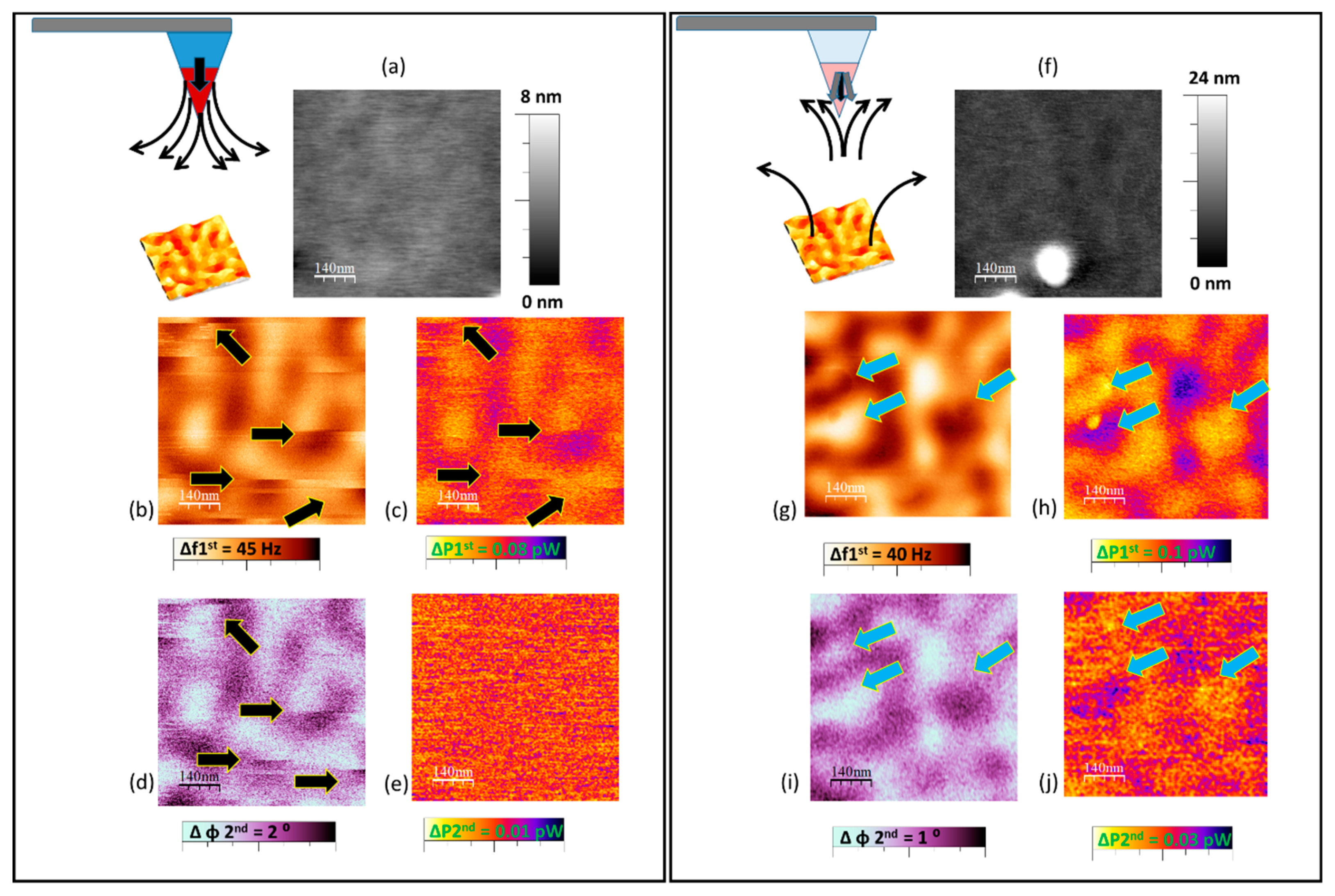
Figure 2 summarizes the result of these experiments where a thin film of CoCr has been measured with two different kinds of MFM probes: a high moment tip (results in the left panel) and a low moment tip (results in the right-side panel). Notice that if the tip stray field is stronger than the coercive field of the sample, reversible or irreversible changes appear in the MFM image due to the perturbations induced by the tip. This effect is observed in the first set of experiments shown in Figure 2a–e. As we can observe, both MFM maps obtained with the frequency shift of the 1st (Figure 2b) and the phase of the 2nd mode (Figure 2d) are similar and the jumps due to modifications of the magnetic state of the sample are present in the two cases. However, a clear difference appears in the dissipation maps: while the contrast in the 1st mode (Figure 2c) is related both to the slight canting of the spins into the magnetic domains and to the sudden changes in the domain structure, the 2nd mode image (Figure 2e) has no significant contrast.
The Figure 2f–j summarize the results obtained with a low-moment-low-coercive probe. In this case, the stray field of the sample could induce spin canting at the tip apex while the magnetic moment of the tip is not sufficient to modify the configuration of the sample. For that reason, instead of the typical jumps in the MFM images some rings and bubbles are observed (Figure 2g,i). Those features correspond to the spin switching or canting processes at the tip apex due to the influence of the sample stray field. They are visible only in the 1st mode MFM map (Figure 2g), however, the 2nd mode MFM image is free of this undesirable effects.
To understand the differences between the two flexural modes we must focus on the amplitudes of both modes. In the bimodal MDFM experiment shown above A2 is much smaller than A1. Iglesias-Freire et al. [13] already predicted the relationship between the shape of the dissipation features and the tip-sample distance and the free oscillation amplitude. When the tip is oscillating in front of the sample, it is visiting regions with different stray field. Larger amplitudes lead to higher variation of the stray field and thus to the increase of the dissipation. However, the influence of the tip stray field onto the domain walls depends only on the tip stray field and on tip-sample distance. To explore the origin of the different features observed in the bimodal MFM images, experiments with different A1/A2 values have been carried out.
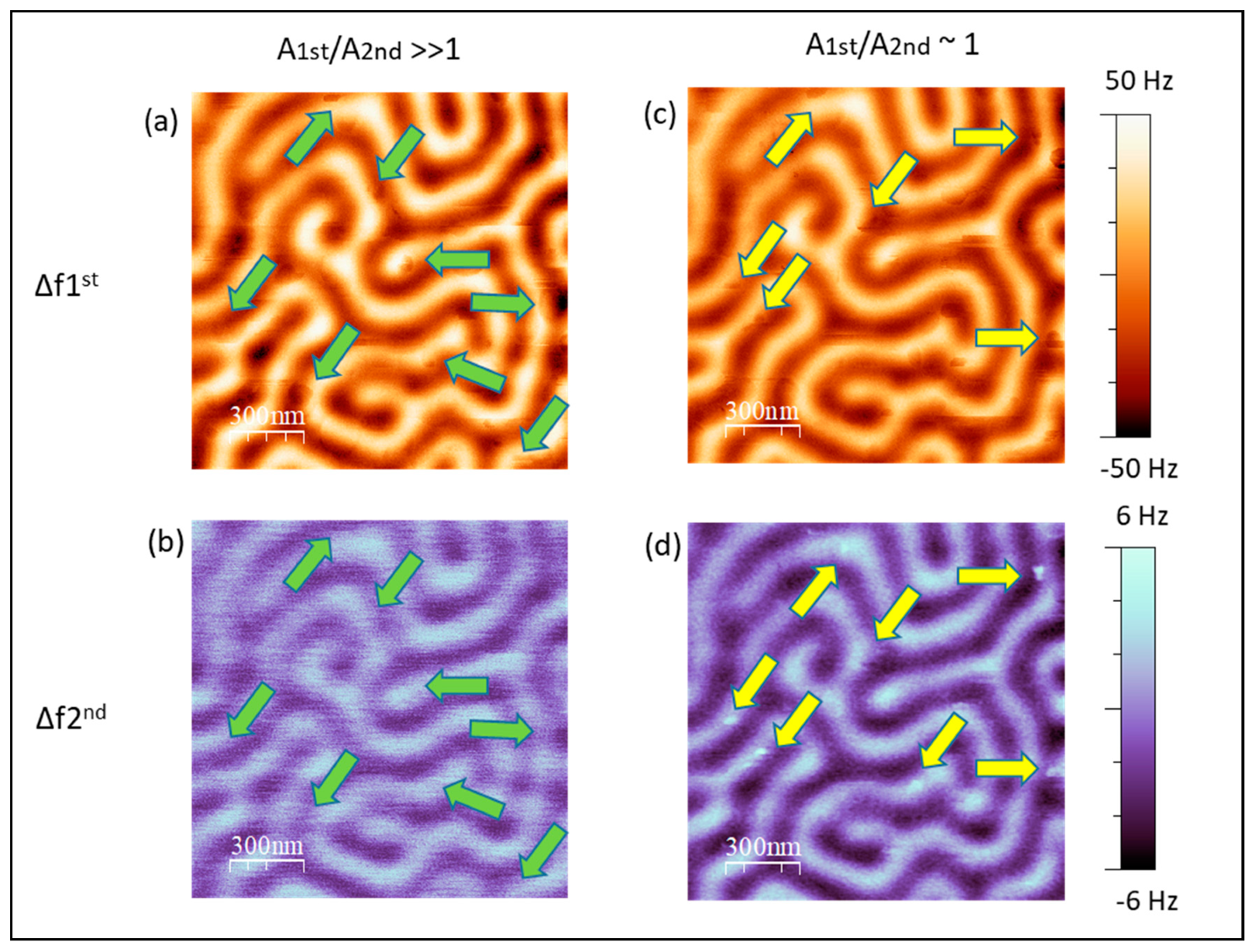
As reported in reference [35], on some occasions the conditions and parameters that give us the maximum dissipation contrast are not the same as those that lead to maximum phase or frequency shift contrast. In fact, Solares and coworkers recommend a choice of the parameters as a function of the quantity that is most relevant to the study. In Figure 3 we demonstrate that increasing the value of the amplitude of the 2nd mode (keeping fixed A1) could drastically change the information that we can achieved in the magnetic images. In Figure 3d the yellow arrows indicate the bright features corresponding to changes of the spins of the tip apex as previously reported. Now this effect is present in both modes (yellow arrows) whereas with the typical ratio between amplitudes (A1/A2 >> 1) it only appears in the magnetic image obtained with the first mode (green arrows).
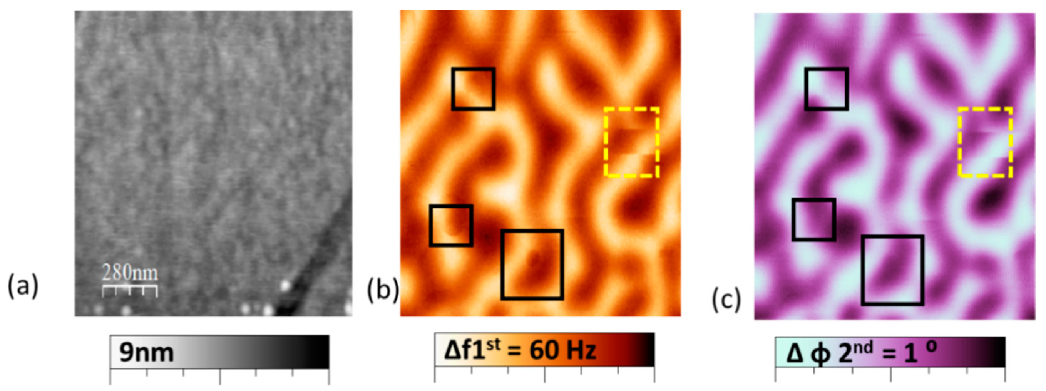
Therefore, we can conclude that if the ratio between amplitudes is A1/A2 >> 1, the bimodal MFM mode is a useful technique to achieve a correct interpretation of the MFM images when the mutual influence between tip and sample is significant as shown in the images in Figure 4. Here the CoCr thin film sample is scanned with a standard MFM probe by using an amplitude of the 2nd mode A2 much smaller than the one of the 1st mode A1 (A1/A2 >> 1). Under this condition, we can visualize which modifications are due to changes in the magnetic configuration of the sample (surrounded by a yellow dotted line in Figure 4b,c) or which are due to the tilt of spins at the tip apex, when they are only seen in the image of the phase or frequency shift of the first mode (black square, solid line in Figure 4b,c).Consequently, if in the second mode we detect changes in the shape of the rings or directly they disappear we can conclude that this effect does not correspond to the magnetization of the sample being then an artifact. If on the contrary, it is detected in the two channels, phase or frequency shift of the 1st and 2nd mode, it can then be stated that it is a change in the magnetic configuration of the sample.

4. Conclusions

In summary, we explore the alternatives that the combination of bimodal MFM with the information given by the experimental dissipation of energy associated to tip-sample interactions offers. Bimodal- MDFM could be a promising technique for increase the possibilities of low dimensional systems characterization. We demonstrated that it is possible to distinguish between tilt of spins at the tip apex and changes in the magnetic state of the sample. Using an amplitude of the second mode A2 much smaller than the one of the first mode A1 (A1/A2 >> 1) the phase shift of the second mode is free of this undesirable effects. These results display a clear advantage of bimodal MFM.

Author Contributions

Conceptualization, M.J. and A.A.; methodology, M.J.; formal analysis, M.J.; investigation, M.J.; resources, A.A.; writing—original draft preparation, M.J. and A.A.; funding acquisition, M.J. and A.A. All authors have read and agreed to the published version of the manuscript.

Funding

This work has been carried out under the support of Spanish Ministry of Science and Innovation under Projects, MAT2016-76824-C3-1-R, PID2019-108075RB-C31, AEI/10.13039/501100011033, “María de Maeztu” Program for Units of Excellence in R&D (MDM-2014-0377) and the Regional Government of Madrid under Project S2018/NMT-4321 NANOMAGCOST-CM, SI1/PJI/2019-00055 and within the framework of the agreement with the Autonomous University of Madrid: Excelencia para el Profesorado Universitario.

Institutional Review Board Statement

Not applicable.

Informed Consent Statement

Not applicable.

Data Availability Statement

The data presented in this study are available upon reasonable request to the corresponding author.

Conflicts of Interest

The authors declare no conflict of interest.

References

  1. Binnig, G.; Rohrer, H. Scanning tunneling microscopy. Surf. Sci. 1983, 126, 236–244. [Google Scholar] [CrossRef]
  2. Binnig, G.; Quate, C.F.; Gerber, C. Atomic Force Microscope. Phys. Rev. Lett. 1986, 56, 930. [Google Scholar] [CrossRef] [PubMed] [Green Version]
  3. Sáenz, J.J.; García, N.; Grütter, P.; Meyer, E.; Heinzelmann, H.; Wiesendanger, R.; Rosenthaler, L.; Hidber, H.R.; Güntherodt, H.-J. Observation of magnetic forces by the atomic force microscope. J. Appl. Phys. 1998, 62, 4293. [Google Scholar] [CrossRef]
  4. Martin, Y.; Wickramasinghe, H.K. Magnetic imaging by “force microscopy” with 1000 Å resolution. Appl. Phys. Lett. 1998, 50, 1455. [Google Scholar] [CrossRef]
  5. Kazakova, O.; Puttock, R.; Barton, C.; Corte-León, H.; Jaafar, M.; Neu, V.; Asenjo, A. Frontiers of magnetic force microscopy. J. Appl. Phys. 2019, 125, 060901. [Google Scholar] [CrossRef]
  6. Rastei, M.V.; Meckenstock, R.; Bucher, J.P. Nanoscale hysteresis loop of individual Co dots by field-dependent magnetic force microscopy. Appl. Phys. Lett. 2005, 87, 222505. [Google Scholar] [CrossRef]
  7. Schwarz, A.; Wiesendanger, R. Magnetic sensitive force microscopy. Nano Today 2008, 3, 28–39. [Google Scholar] [CrossRef]
  8. Jaafar, M.; Gómez-Herrero, J.; Gil, A.; Ares, P.; Vázquez, M.; Asenjo, A. Variable-field magnetic force microscopy. Ultramicroscopy 2009, 109, 693–699. [Google Scholar] [CrossRef]
  9. Coïsson, M.; Barrera, G.; Celegato, F.; Manzin, A.; Vinai, F.; Tiberto, P. Magnetic vortex chirality determination via local hysteresis loops measurements with magnetic force microscopy. Sci. Rep. 2016, 6, 1–9. [Google Scholar] [CrossRef] [Green Version]
  10. Ares, P.; Jaafar, M.; Gil, A.; Gõmez-Herrero, J.; Asenjo, A. Magnetic Force Microscopy in Liquids. Small 2015, 11, 4731–4736. [Google Scholar] [CrossRef] [Green Version]
  11. Grütter, P.; Liu, Y.; LeBlanc, P.; Dürig, U. Magnetic dissipation force microscopy. Appl. Phys. Lett. 1998, 71, 279. [Google Scholar] [CrossRef] [Green Version]
  12. Torre, B.; Bertoni, G.; Fragouli, D.; Falqui, A.; Salerno, M.; Diaspro, A.; Cingolani, R.; Athanassiou, A. Magnetic Force Microscopy and Energy Loss Imaging of Superparamagnetic Iron Oxide Nanoparticles. Sci. Rep. 2011, 1, 1–8. [Google Scholar] [CrossRef] [PubMed] [Green Version]
  13. Iglesias-Freire, Ó.; Bates, J.R.; Miyahara, Y.; Asenjo, A.; Grütter, P.H. Tip-induced artifacts in magnetic force microscopy images. Appl. Phys. Lett. 2013, 102, 022417. [Google Scholar] [CrossRef] [Green Version]
  14. Lohau, J.; Kirsch, S.; Carl, A.; Dumpich, G.; Wassermann, E.F. Quantitative determination of effective dipole and monopole moments of magnetic force microscopy tips. J. Appl. Phys. 1999, 86, 3410. [Google Scholar] [CrossRef]
  15. Hug, H.J.; Stiefel, B.; van Schendel, P.J.A.; Moser, A.; Hofer, R.; Martin, S.; Güntherodt, H.-J.; Porthun, S.; Abelmann, L.; Lodder, J.C.; et al. Quantitative magnetic force microscopy on perpendicularly magnetized samples. J. Appl. Phys. 1998, 83, 5609. [Google Scholar] [CrossRef] [Green Version]
  16. Vock, Z.S.S.; Alexei, L.S.; Bogdanov, N. Quantitative Magnetic Force Microscopy Study of the Diameter Evolution of Bubble Domains in a Co/Pd Multilayer. IEEE Trans. Magn. 2011, 47, 2352. Available online: https://ieeexplore.ieee.org/stamp/stamp.jsp?arnumber=6028183 (accessed on 30 September 2021). [CrossRef]
  17. Benassi, A.; Marioni, A.M.; Passerone, D.; Hug, H.J. Role of interface coupling inhomogeneity in domain evolution in exchange bias ETH Library. Sci. Rep. 2014, 4, 4508. [Google Scholar] [CrossRef] [Green Version]
  18. Gisbert, V.G.; Amo, C.A.; Jaafar, M.; Asenjo, A.; Garcia, R. Quantitative mapping of magnetic properties at the nanoscale with bimodal AFM. Nanoscale 2021, 13, 2026–2033. [Google Scholar] [CrossRef]
  19. Garcia, R.; Herruzo, E.T. The emergence of multifrequency force microscopy. Nat. Nanotechnol. 2012, 7, 217–226. [Google Scholar] [CrossRef] [Green Version]
  20. Benaglia, S.; Gisbert, V.G.; Perrino, A.P.; Amo, C.A.; Garcia, R. Fast and high-resolution mapping of elastic properties of biomolecules and polymers with bimodal AFM. Nat. Protoc. 2018, 13, 2890–2907. [Google Scholar] [CrossRef]
  21. Thompson, H.T.; Barroso-Bujans, F.; Herrero, J.G.; Reifenberger, R.; Raman, A. Subsurface imaging of carbon nanotube networks in polymers with DC-biased multifrequency dynamic atomic force microscopy. Nanotechnology 2013, 24, 135701. [Google Scholar] [CrossRef] [PubMed]
  22. Li, J.W.; Cleveland, J.P.; Proksch, R. Bimodal magnetic force microscopy: Separation of short and long range forces. Appl. Phys. Lett. 2009, 94, 163118. [Google Scholar] [CrossRef]
  23. Dietz, C.; Herruzo, E.T.; Lozano, J.R.; Garcia, R. Nanomechanical coupling enables detection and imaging of 5 nm superparamagnetic particles in liquid. Nanotechnology 2011, 22, 125708. [Google Scholar] [CrossRef] [PubMed]
  24. Schwenk, J.; Marioni, M.; Romer, S.; Joshi, N.R.; Hug, H.J. Non-contact bimodal magnetic force microscopy. Appl. Phys. Lett. 2014, 104, 112412. [Google Scholar] [CrossRef] [Green Version]
  25. Iglesias-Freire, Ó.; Jaafar, M.; Berganza, E.; Asenjo, A. Customized MFM probes with high lateral resolution. Beilstein J. Nanotechnol. 2016, 7, 1068–1074. [Google Scholar] [CrossRef] [Green Version]
  26. Neu, V.; Vock, S.; Sturm, T.; Schultz, L. Epitaxial hard magnetic SmCo5 MFM tips—A new approach to advanced magnetic force microscopy imaging. Nanoscale 2018, 10, 16881–16886. [Google Scholar] [CrossRef]
  27. Jaafar, M.; Iglesias-Freire, Ó.; García-Mochales, P.; Sáenz, J.J.; Asenjo, A. Negative dissipation gradients in hysteretic materials. Nanoscale 2016, 8, 16989–16994. [Google Scholar] [CrossRef]
  28. Krivcov, A.; Junkers, T.; Möbius, H. Understanding electrostatic and magnetic forces in magnetic force microscopy: Towards single superparamagnetic nanoparticle resolution. J. Phys. Commun. 2018, 2, 075019. [Google Scholar] [CrossRef]
  29. Ciuta, G.; Dumas-Bouchiat, F.; Dempsey, N.M.; Fruchart, O. Some aspects of magnetic force microscopy of hard magnetic films. IEEE Trans. Magn. 2016, 52, 1–8. [Google Scholar] [CrossRef] [Green Version]
  30. Cinar, I.; Lacour, D.; Montaigne, F.; Puliafito, V.; Watelot, S.P.; Hehn, M.; Finocchio, G.; Ozatay, O.; Hauet, T. Artifacts in magnetic force microscopy under in-plane applied magnetic field: Magnetic bubble as a case study. J. Magn. Magn. Mater. 2020, 500, 166296. [Google Scholar] [CrossRef]
  31. Jaafar, M.; Iglesias-Freire, O.; Serrano-Ramón, L.; Ibarra, M.R.; de Teresa, J.M.; Asenjo, A. Distinguishing magnetic and electrostatic interactions by a Kelvin probe force microscopy- magnetic force microscopy combination. Beilstein J. Nanotechnol. 2011, 2, 552–560. [Google Scholar] [CrossRef] [PubMed] [Green Version]
  32. Neves, C.S.; Quaresma, P.; Baptista, P.V.; Carvalho, P.A.; Araújo, J.P.; Pereira, E.; Eaton, P. New insights into the use of magnetic force microscopy to discriminate between magnetic and nonmagnetic nanoparticles. Nanotechnology 2010, 21, 305706. [Google Scholar] [CrossRef] [PubMed]
  33. Horcas, I.; Fernández, R.; Gómez-Rodríguez, J.M.; Colchero, J.; Gómez-Herrero, J.; Baro, A.M. WSXM: A software for scanning probe microscopy and a tool for nanotechnology. Rev. Sci. Instrum. 2007, 78, 013705. [Google Scholar] [CrossRef] [PubMed]
  34. Cleveland, J.P.; Anczykowski, B.; Schmid, A.E.; Elings, V.B. Energy dissipation in tapping-mode atomic force microscopy. Appl. Phys. Lett. 1998, 72, 2613. [Google Scholar] [CrossRef] [Green Version]
  35. Diaz, A.J.; Eslami, B.; López-Guerra, E.A.; Solares, S.D. Selection of higher eigenmode amplitude based on dissipated power and virial contrast in bimodal atomic force microscopy. J. Appl. Phys. 2014, 116, 104901. [Google Scholar] [CrossRef]
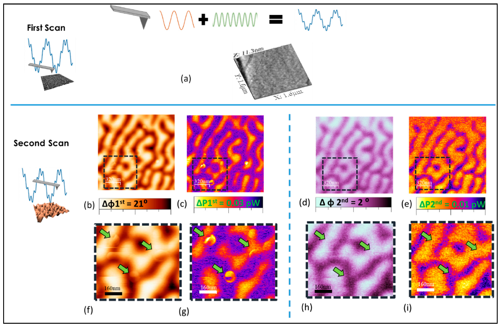
Figure 1. The upper panel corresponds to the first scan where the topography (a) is detected. The lower panel corresponds to the retrace scan where magnetic long-range interaction is dominant: (b) standard MFM signal corresponding to the phase of the 1st mode; (c) dissipation map corresponding to the 1st mode calculated by Equation (1). (d,e) phase and dissipation map of the 2nd mode. Images size: 1.6 μm × 1.6 μm. A1 = 20 nm. A2 = 5 nm. Z lift distance = 30 nm. (f) is a zoom of the MFM image (b,g) is a zoom of the dissipation map corresponding to the 1st mode (c) where rings and stronger bright contrast that correspond to dissipation-related features can be easily distinguished superposed to the magnetic domain configuration (marked with green arrows). (h,i) are the equivalent zooms of the images corresponding to the second mode (d,e) where it is not clear the presence of the dissipation related features at the same positions (green arrows).
Applsci 11 10507 g001
Figure 2. Different tip-sample interactions. Left panel corresponds to a Bimodal MDFM experiment with a high moment magnetic tip and right panel corresponds to a similar experiment with a low moment MFM tip: (af) topography of the sample (CoCr film), (b,g) frequency shift of the first mode during the second scan where the magnetic signal is detected. (d,i) phase of the second mode during the retrace scan. (c,h) are the dissipation maps calculated with Equation (1) and the parameters corresponding to the 1st mode (e,j) are the dissipation maps of the 2nd mode. All the dissipation maps are calculated during the retrace scan. The black arrows indicate tip induced magnetic reversal whereas blue arrows indicate dissipation-related features due to spin canting at the tip apex. Images size: 0.7 μm × 0.7 μm. A1 = 20 nm. A2 = 0.75 nm. Z lift distance = 30 nm.
Applsci 11 10507 g002
Figure 3. Different A1/A2.ratio Left panel corresponds to a typical Bimodal MDFM experiment where the amplitude of the first mode is much higher than the amplitude of the second mode. Right panel corresponds to another set of measurements where the amplitude of both modes is similar. A PLL is enabled in all cases. (a,b) are the frequency shift channels of the first and the second mode at a retrace distance of 10 nm. (c,d) are the frequency shift channels of the first and the second mode at a retrace distance of 10 nm when the A1/A2 ratio is nearly 1. In that case the dissipation-related features (yellow arrows) appear at both channels whereas if the typical ratio between amplitudes is used (A1/A2 >> 1) these features only appear in the magnetic image obtained with the first mode (green arrows). The sample is a FePd thin film. Images size: 1.5 μm × 1.5 μm.
Applsci 11 10507 g003
Figure 4. (a) Topography of the sample (CoCr thin film), (b) frequency shift of the first mode during the second scan (MFM signal), (c) phase of the second mode, second scan. The black squares indicate dissipation-related features in the magnetic image (only present in the f1 image) whereas the yellow dotted line remarks a change in the magnetic configuration of the sample due to the tip stray field. Images size: 1.4 μm × 1.4 μm. A1 = 20 nm. A2 = 0.75 nm. Z lift distance = 30 nm.
Applsci 11 10507 g004
Publisher’s Note: MDPI stays neutral with regard to jurisdictional claims in published maps and institutional affiliations.