1. Introduction
Printed reflectarray (RA) antennas are nowadays a well-assessed technology for a wide range of applications. In comparison with other high-gain antenna configurations, they present several advantages, such as reduced weight, the possibility of being easily stored when folded and easy deployment. All these features make RAs suitable for several functions [
1,
2,
3,
4,
5,
6,
7,
8], including mobile communication systems.
In such applications, in addition to good performance, it is often also required that the adopted antennas present a low profile. Traditional reflectarrays, unfortunately, do not satisfy this requirement since they adopt a spatial feed system. A solution to this problem was firstly introduced in [
9] and then improved by several authors (see [
10,
11,
12,
13,
14]): it consists in using a folded reflectarray, in which the presence of a polarization layer allows to approximately halve the thickness of the entire RA with respect to a traditional configuration. An alternative solution to reduce the antenna volume can be that of fitting the reflector to the surface, where it has to be mounted, and fixing the feed not to the reflector itself, but to another part of the structure where the antenna is located. In the case in which the supporting structure is the fuselage of an airplane or the curved sidewall of a ship, the RA can be no longer flat.
The available literature on conformal reflectarrays is still quite limited. In [
15], the differences among the performance of a planar, a concave and a convex reflectarray are discussed, while in [
16,
17,
18], the effect of the curvature on the radiation features of several convex configurations is numerically investigated. As expected, what emerges from these analyses is that concave RAs are characterized by better performance, but they are less interesting from the application point of view since they are very close to conventional reflectors, while convex reflectarrays are more attractive, but their performance decreases as the surface curvature increases. In [
19,
20], some preliminary results on the experimental characterization of cylindrically conformal reflectarrays are shown: in [
19], a center-fed RA is considered, realized with variable-depth grooves in a completely metallic structure, while the antenna presented in [
20] is an off-set configuration, using printed re-radiating square patches. The results presented in both these papers confirm those obtained through the analysis in [
16,
17,
18]: a convex RA is more critical than a planar one in terms of maximum gain, and therefore, efficiency, bandwidth, and side lobe level (SLL), especially in the plane affected by the curvature; for this reason, particular care must be taken in its design, adopting, when possible, the techniques developed for planar RAs and, if necessary, introducing new ones.
In the literature, many alternatives are presented to increase reflectarrays’ bandwidth and efficiency, most of them based on the introduction and use of re-radiating elements with enhanced properties [
21,
22]; some of the solutions presented in these papers can be extended also to the case of convex conformal reflectarrays (indicated in the following of this paper as CRAs), and they could enhance its bandwidth, but they would not affect its efficiency and would not help to reduce the SLL.
In order to improve the performance of a CRA, an innovative approach is here introduced, according to which the feed is considered a further degree of freedom of the whole antenna system, and it is designed to optimize the entire antenna performance. This is quite different with respect to what it is generally done for planar RAs since the most-used RA feed is a suitable commercial horn, selected to guarantee good antenna performance, such as high efficiency and low cross-polarization.
There are few exceptions to this, such as the solution proposed in [
23], based on the design of an ad hoc feed, consisting of a coupled tapered slot-line antenna to obtain a uniform illumination of the reflectarray aperture in one plane, or that in [
24], where the use of non-symmetric feeds uniformly illuminating the antenna aperture for both centered or off-set positions is suggested. The solutions proposed in [
24] enhance the planar RA performance, but at the cost of an increase in the feed complexity and size. Both in [
23] and in [
24], the reflectarray is planar; according to the authors’ knowledge, the design of a convex RA whose features are enhanced by playing with the design of a
ad hoc has never been proposed in the literature.
According to the procedure here introduced, first the features of the feed are determined, considering the entire antenna system: the results, summarized in
Section 5, prove that the proposed solution not only maximizes the antenna efficiency, but allows also to control the SLL, despite what is possible with other commonly adopted feed horns. Then, a proper architecture for its manufacturing is selected: here, it was decided to adopt a smooth-wall configuration, where the desired radiation pattern is obtained by exploiting a series of slope variations along the horn profile since it is an effective, easy-to-realize geometry that presents the further advantage of being particularly suitable for 3D-printing manufacturing, leading to fast and low-cost prototyping [
25,
26].
2. Convex Conformal Reflectarrays
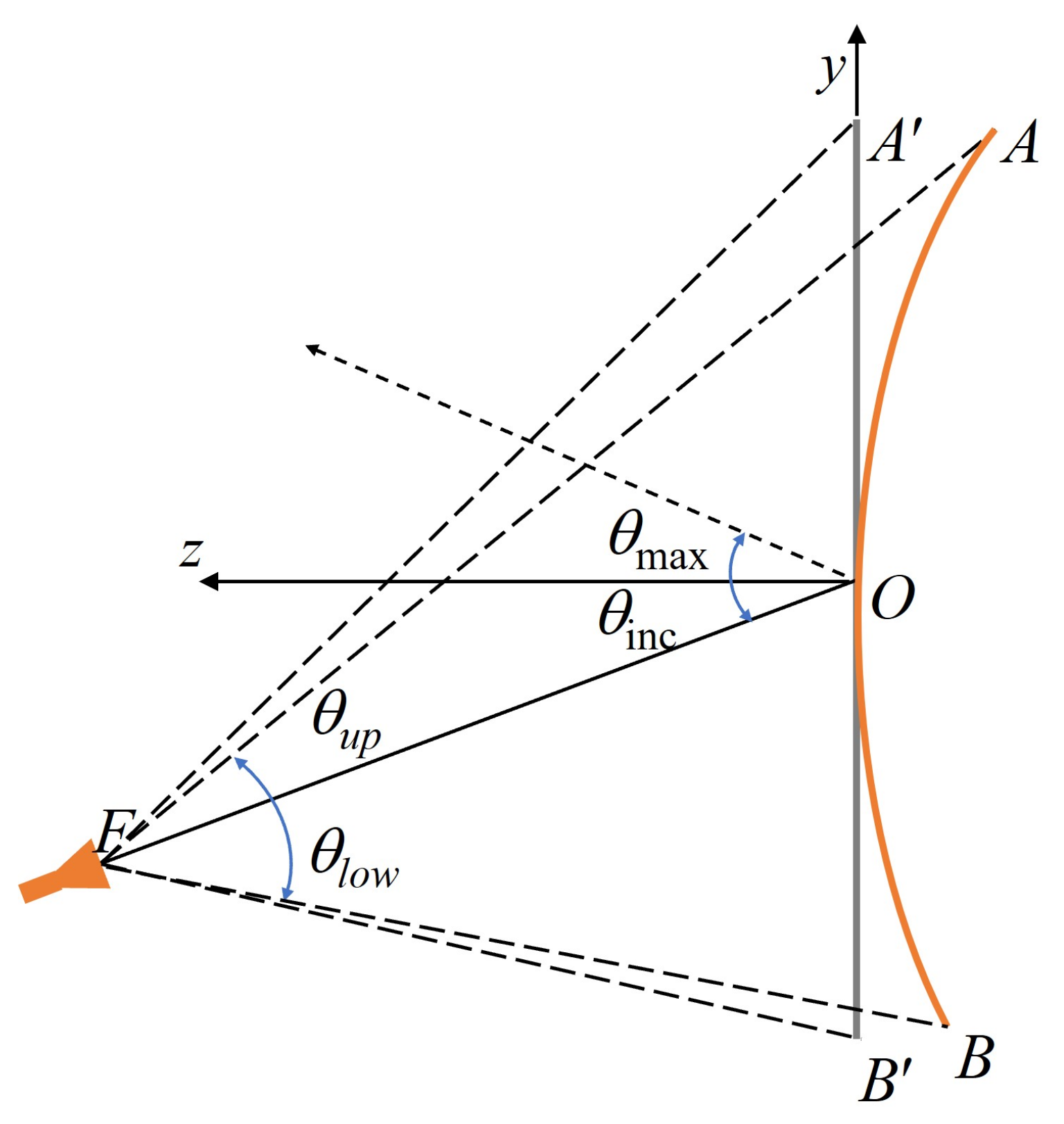
The CRA considered here is that already described in [
20]: its main characteristics are summarized, for the sake of clarity, in the following. The design was made to operate in the Ka-band, in a frequency interval centered at
GHz; the re-radiating elements are square patches, located on a rectangular grid, whose unit cell has a size of
at
, and are printed on a substrate of Diclad 527, 0.8 mm thick, with
and
.
The size of the equivalent planar reflector is
mm and it was subsequently bent to a cylinder with a radius of curvature
, as shown in
Figure 1, where the lateral view of the CRA is sketched. The antenna radiates a pencil beam at
in the
plane; the position of the feed is specular to the direction of maximum radiation and
, being that
f (
in
Figure 1) is the distance from the feed to the center of the reflector.
The results reported in [
20] relevant to the experimental characterization of a CRA prototype, using a standard rectangular horn as feed, show a gain of 29.7 dB at
, a measured efficiency of almost
, a 1 dB bandwidth of about
and relatively high SLL (see
Table 1), especially in the E-plane, where the effect of the curvature is more remarkable and tends to scatter the radiated field in many directions instead of focusing it in a desired one. Note that the relatively narrow bandwidth is also due to the difference between the phase of the incident field in correspondence with the upper and lower edges of the CRA requiring the use of re-radiating patches with different sizes that are characterized by a different frequency dependence of their phase. The different path between the feed and the upper or lower edge occurs also in planar RAs, but here, it is enhanced by the curvature. For what concerns the efficiency, it is worth to observe that the curvature reduces the effective area with respect to the planar case.
The aim of the work in [
20] was to prove the feasibility of a CRA and, therefore, its performance was not optimized. However, those results reveal the need for some further optimization for improving the antenna performance, specifically for convex RAs for which the techniques commonly adopted for planar reflectarray, such as the use of multilayer re-radiating elements [
21], are not applicable.
For this reason, an innovative approach is here introduced that considers the antenna system in its entirety, and the feed is a further degree of freedom to be exploited for enhancing the CRA performance.
3. Feed Design Procedure
As it is well known, the use of an optimal illumination system is central for increasing the gain of a reflector [
27] or a reflectarray [
1,
4]. However, the feed is designed or selected (as most frequently occurs in RA cases) firstly by defining the constraints it must satisfy and then evaluating its stand-alone performance. Moreover, in [
28], numerical results are shown as the first demonstration on a co-design procedure, where the feed horn for an off-set reflector is optimized, also taking, in some way, into account the presence of the reflector itself: at each step of the optimization process, a different horn configuration is simulated with an accurate but also highly computationally expensive FEM approach and then the obtained radiation pattern is used in the physical optics based simulation of the reflector.
The innovative procedure described in the following is based on the idea of designing an ad hoc feed to optimize the entire antenna system performance: it differs not only from what it is commonly shown in the literature on RAs, but also from what it is proposed in [
28], where numerical results are shown as first demonstration of a co-design procedure, according to which the feed horn for an off-set reflector is optimized, also taking, in some way, into account the presence of the reflector itself since the way in which the optimization of the entire antenna system is performed is different. In the present case, the definition of the optimum feed for enhancing the CRA performance cannot be managed as a classical optimization problem in which the entire antenna system is simulated with a full-wave approach since it would require a huge computational time. For this reason, it is necessary to decouple the overall electromagnetic problem into two main steps: contrarily to what is done in [
28], first a full-wave analysis of the convex reflectarray, with a simplified model of the feed, is performed and used to optimize the performance of the entire system; then, the actual structure for the feed, with the same features, is derived.
In the first step of the procedure, the antenna configuration in
Figure 1 is considered, but the feed is substituted with an open-ended circular aperture, with radius
R, located in the same position. The overall system is simulated with CST Microwave Studio, computing the radiation patterns
for single mode incidents separately on the open-ended circular aperture. The total radiation pattern is, therefore, equal to the sum of
weighted by the relevant complex amplitude of the modes on the circular aperture
, i.e., the following:
where the sum is limited to the number
N of modes above the cut-off at the horn aperture, and
i represent both the azimuthal and radial indexes,
m and
n. This simplified model does not consider the effect of the external profile of the horn and the modal coupling at the aperture. Note that if step or slope discontinuities are used and the antenna is fed by the
mode, only the modes with
(i.e.,
and
) are excited and, therefore, considered in the previous sum.
The aim of the optimization process is to determine the radius
R of the aperture, the number
N of modes and the set of
that allows to maximize the CRA gain and to minimize its cross-pol and SLL. This is obtained through the minimization of the function as follows:
where
is the gain of an equivalent uniform aperture, and
is the actual antenna gain;
,
and
are weights varying between 0 and 1 to give more or less emphasis to one term or to another. Finally,
is the vector collecting the complex amplitudes that have to satisfy the further condition that the overall input power is 1 W (i.e.,
).
The radius R and the number of modes N are handled in a different way; for what concerns R, its increase improves the system performance, but a too-large aperture will correspond to a too-bulky horn, and therefore, R is selected as the best compromise between these two opposite constraints. The choice of N is made instead, optimizing the antenna performance with an increasing number of modes and stopping when the improvement is below a fixed threshold. Following these criteria, the best value for R results to be 18 mm, while only the first two modes (i.e., and ) significantly contribute to the antenna radiation pattern.
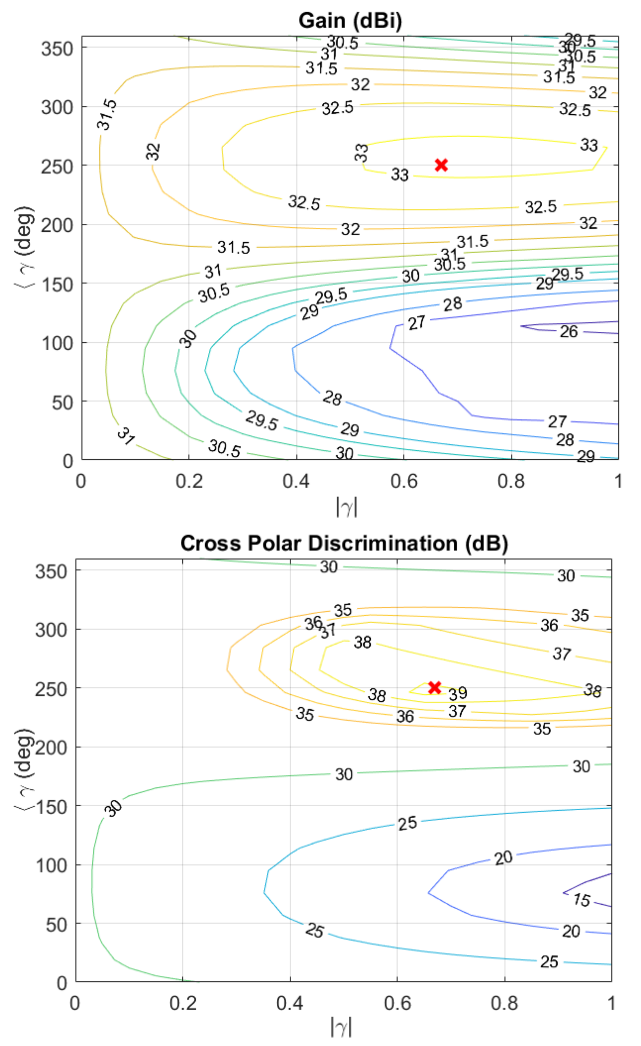
Once these parameters are determined, it is possible to proceed with the optimization. The maps in
Figure 2 show the iso-level curves of the system gain, maximum cross-polarization and side lobe level discrimination that are reported as a function of the magnitude (
) and phase (
) of the ratio
of the
to the
modal coefficient:
, evaluated at
(30 GHz). The best compromise, by considering the overall operative frequency band
GHz, is represented by
. According to the curves in
Figure 2, this choice will guarantee that the whole antenna is characterized by a gain of at least 33 dB (see plot on the top of
Figure 2), a maximum SLL (in the horizontal plane) approximately equal to −23 dB and a cross polarization level of around −37 dB. The numerical and experimental characterizations of the entire antenna system confirm these expected results.
It is interesting to note that, from the design maps reported in
Figure 2, it is possible to derive that a Potter horn solution (
and
modes in phase in power ratio
[
29]) would lead to worse performance (gain around 30.5 dB, maximum cross-polarization protection 28 dB). Moreover, such a horn, with aperture radius
mm, would present six modes with
above cut-off at 30 GHz (i.e.,
and
with
); then, a quite long slope would be necessary to minimize the excitation of the other modes.
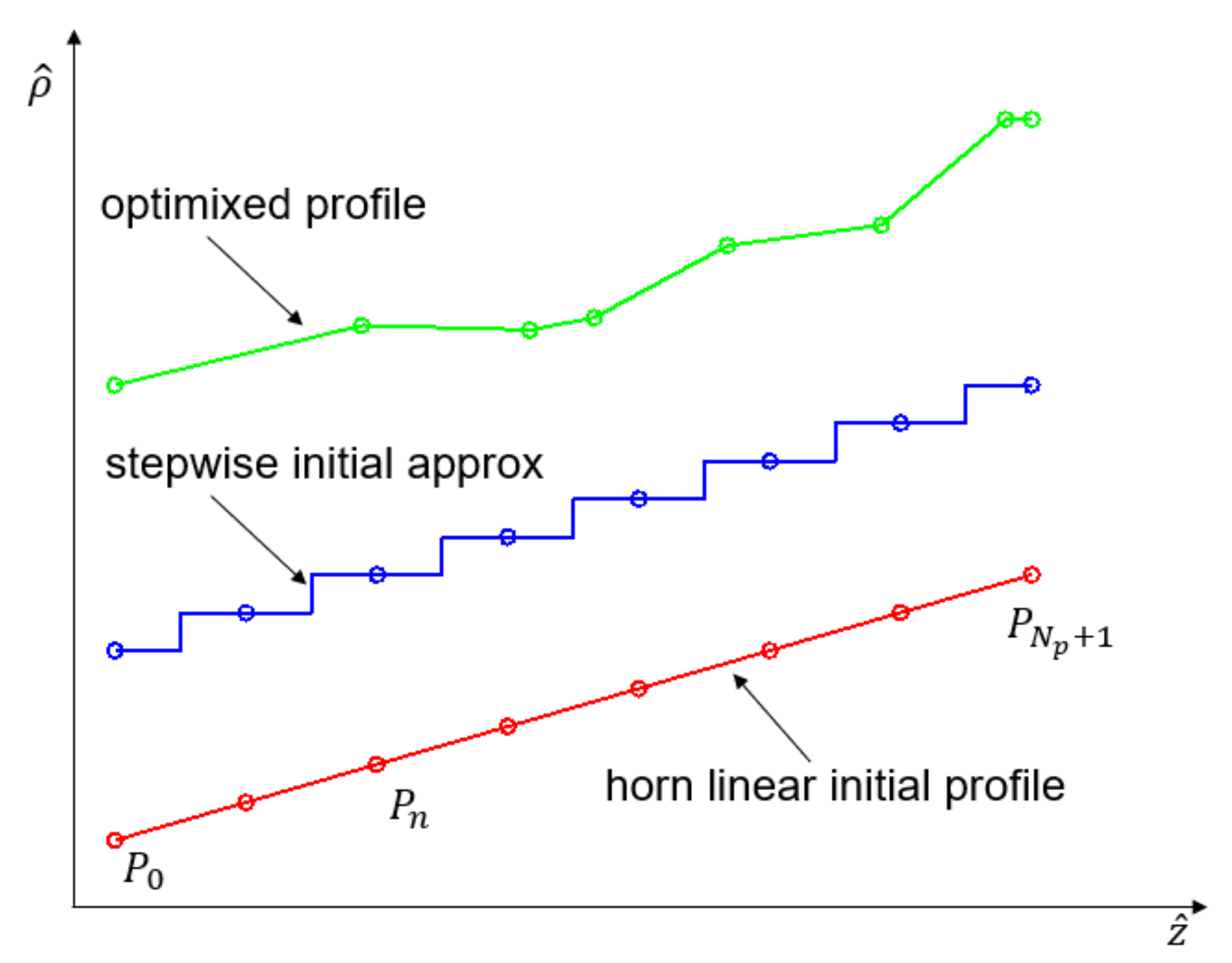
The second step of the developed procedure involves the horn actual synthesis. In principle, different horn architectures can be exploited, but the smooth wall one is preferred since it can be more easily realized and it is less sensitive to manufacturing tolerances. The geometry was obtained by applying an optimization scheme aimed to obtain a suitable profile for the horn generatrix, starting from a linear one. To this end, a set of
, equidistant points
are initially located on the generatrix profile, where the initial point (
) and the final one (
) are placed to fit the radii
of the waveguide connected to the horn and
R of its circular aperture (see
Figure 3).
The optimization process consists in modifying the radial (
) and longitudinal (
) coordinates of the
internal nodes
collected in the vector
in order to minimize a proper cost function defined as a weighted sum of the horn reflection coefficient, the horn cross-polarization level and the distance between the actual (
) and desired (
) modal content on the horn aperture:
where
,
and
are the weights used to give more or less emphasis to the different terms in
. Since the operating frequency band is of the order of
,
was shown to be sufficient to achieve the desired performance. The analysis was carried out exploiting a coupled integral equation technique (CIET) [
30]. A stepwise approximation of the initial linear profile of the horn was generated (see
Figure 3). In the optimization, the discretization step was chosen to be equal to
, while
was chosen for the final analysis, where
is the free-space wavelength at 30 GHz. The final horn geometry in terms of longitudinal and radial
coordinates is characterized by the following:
- -
mm;
- -
mm.
The 3D model of the horn is shown on the left of
Figure 4. It is worth to mention that, if larger bandwidth or multi-band applications are required, a larger number of
would be necessary, but this design approach can be applied anyway.
4. Feed Manufacturing and Testing
For fast prototyping of the horn, its realization through 3D printing was considered. In particular, the selective laser melting (SLM) process was exploited, using an EOSINT M270 Dual Mode machine that has a building volume of 250 mm × 250 mm × 215 mm. In comparison with corrugated feed horns, the smooth-wall architecture is particularly suitable for SLM manufacturing. Indeed, this feed horn architecture does not present overhanging surfaces when the building direction is oriented along the propagation axis. Moreover, supporting structures are reduced or not necessary also for the external surfaces. For the measurement of the antenna system, an adapter from rectangular (WR28) to circular waveguide was integrated in the horn. The overall feed dimensions are 52 mm × 52 mm × 53.7 mm.
Although results are already available in the literature (see, for example, [
31]), the manufacturing of SLM components in the Ka band is still challenging in terms of accuracy. A fine tuning of the process parameters was carried out: the effect of the part shrinkage related to the high temperature gradients in the melting process was taken into account by introducing scaling factors in the transversal directions. Moreover, laser beam offsets were applied to consider the melted powder outside the nominal antenna shape. The SLM antenna prototype in AlSi10Mg alloy is shown on the right of
Figure 4.
The horn was first simulated with CST Microwave Studio, and then measured in an anechoic chamber; the gain at the central frequency is 17 dB. The plots in
Figure 5 show the comparison between measured and simulated radiation patterns in the
-cuts
and
for the central, lower and upper frequencies of the band. The good agreement confirms the manufacturing quality of the horn. It is also worth noting that its performance is very stable with the frequency.
In
Figure 6, the simulated frequency behavior of the horn
and of its simulated and measured cross-polarization level are plotted. In the range of frequencies of interest, the amplitude of
is always below −34 dB, confirming the excellent matching, while the cross-pol is lower than −37 dB, confirming the effectiveness of the adopted design procedure. The values of the cross-pol obtained through the experimental characterization of the manufactured feed, in correspondence with seven frequency points in the interval [28.5, 31.5] GHz, are in good agreement with the simulations.
5. Optimized CRA: Numerical and Experimental Characterization
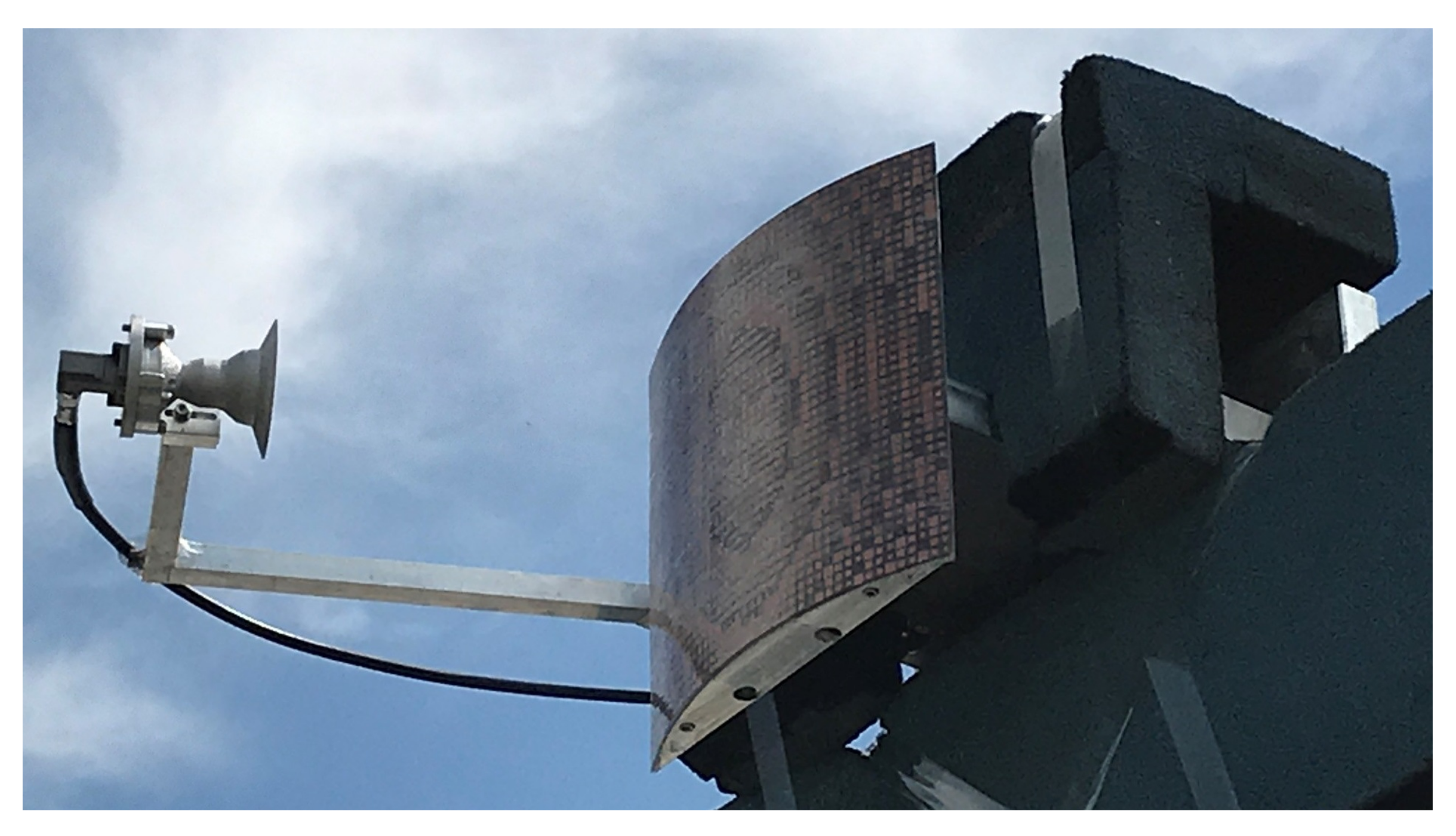
Once the feed horn performance was assessed, the whole CRA system was assembled and it was numerically and experimentally characterized.
Figure 7 shows the entire CRA antenna mounted on the outdoor test range at Politecnico di Torino. The relative position between the feed and the convex reflector was kept the same as the configuration in [
20]. In addition, in this case, the simulations were carried out with CST Microwave Studio.
The computed and measured radiation patterns at 29, 30 and 31 GHz are shown in
Figure 8,
Figure 9 and
Figure 10. In each figure, the simulated co-polar patterns in the E (vertical) and H (horizontal) planes are plotted; moreover, both the measured co-polar and cross-polar components are represented. From the plots, it can be seen that there is very good agreement between the simulated and measured results.
As far as the system performance is concerned, it must be noticed that it is very good also in the vertical plane, it is the most affected by the CRA curvature, and it remains almost constant over the considered band. The cross-polarization reaches a maximum value of −25 dB in the H-plane at the frequency of 31 GHz, while in the E plane, it is always fully below −30 dB; this is also thanks to the performance of the designed feed. The values of the maximum SLL are reported in columns 2 and 4 of
Table 1 for the E and H planes, respectively. In the same table, the SLL in the two planes for the configuration introduced in [
20] is also shown (column 3 and column 5) for the sake of comparison: the optimized configuration proposed here exhibits side lobes that are lower at least 2 dB in the E-plane and from 3 dB to 5 dB in the H-plane than those for the antennae in [
20]. Note that in addition to
, in
Table 1, the frequencies of 29.2 GHz and 30.8 GHz are considered since those are the values limiting the bandwidth for the configuration in [
20]. In fact, as it emerges from
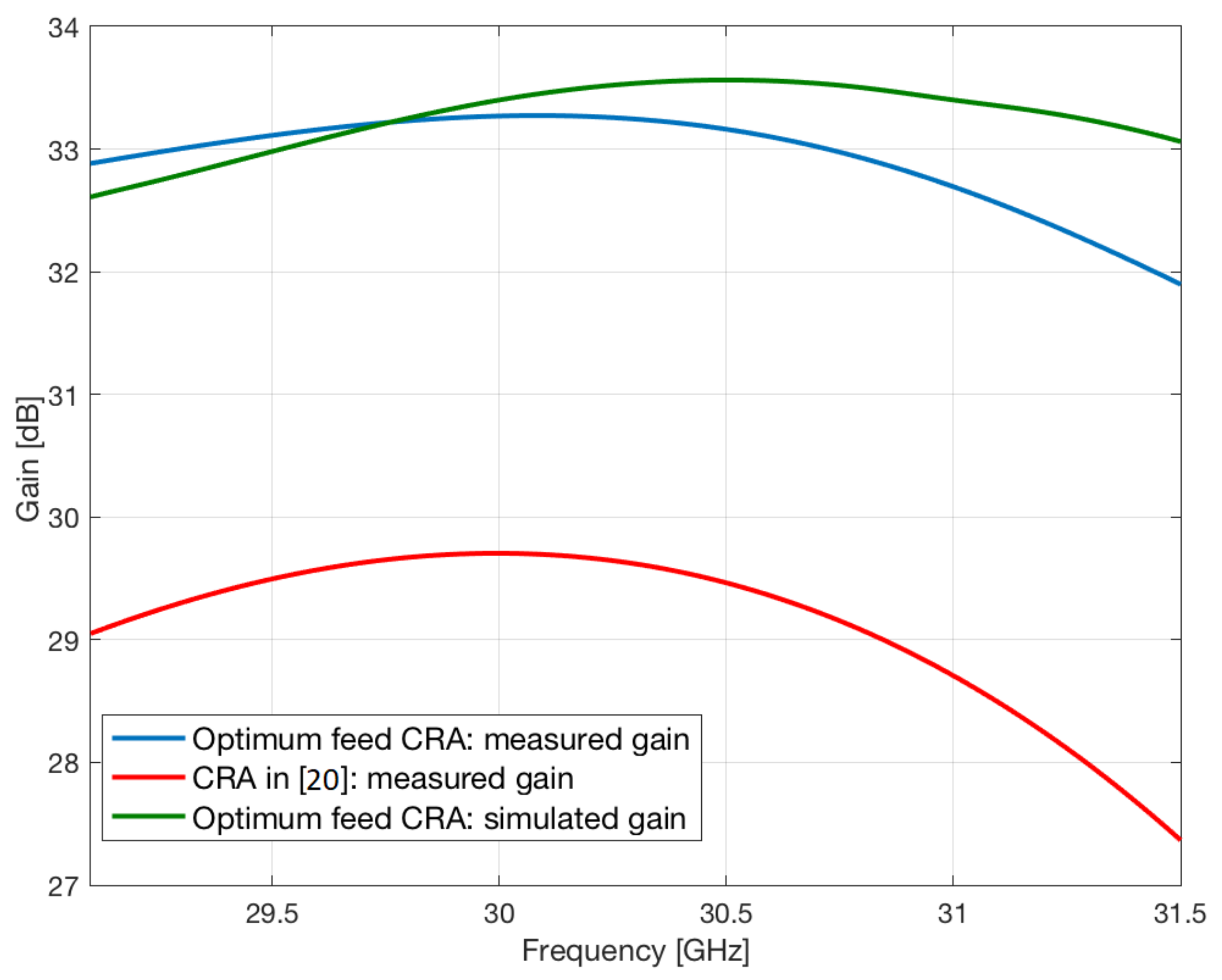
Figure 11, where the frequency behavior of the simulated and measured gain of the CRA considered here and of the measured one for the configuration in [
20] are shown, for frequencies beyond 30.8 GHz, the gain of the latter strongly decreases.
The curves in
Figure 11 show the good agreement between the numerical and experimental results and the improvement of the performance obtained with the optimized configuration; the gain is greater by almost 3 dB in the 1-dB bandwidth than that of the antenna in [
20] (see also columns 6 and 7 in
Table 1); the bandwidth on its turn is increased from 7 % to 11 %. The increase in the gain is also responsible for a significant improvement in the antenna efficiency that is more than twice at all the three frequencies, as it emerges also from columns 8 and 9 of
Table 1.
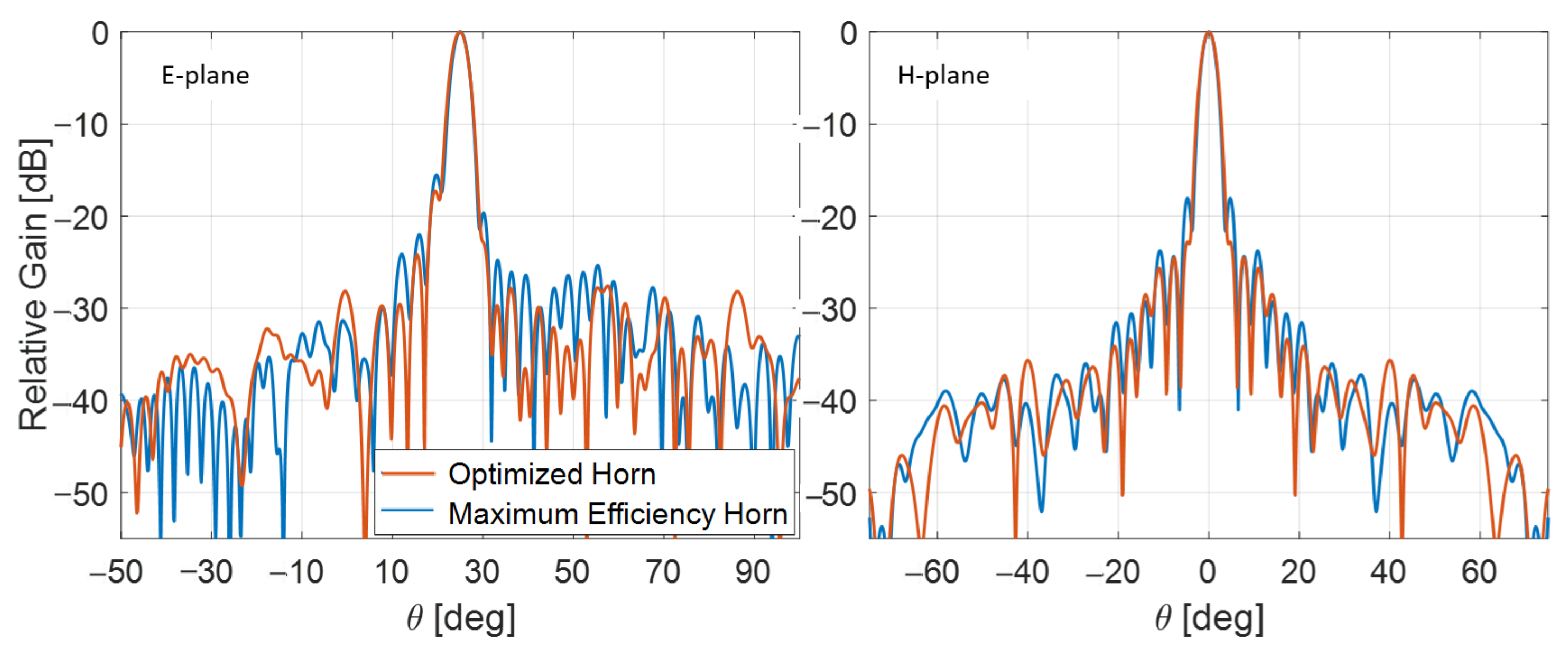
To further prove the effectiveness of the proposed technique, a comparison with the performance of the CRA illuminated with a feed designed for optimizing the antenna system efficiency is also carried out. As reported in [
1,
4], similar to what is commonly done for reflectors, in case of RAs, the aperture efficiency can be evaluated as the product of several terms, the most significant of which is the illumination efficiency and the spillover efficiency, which can be evaluated numerically (see, for example, [
4]). If, as is done in most of the cases, the radiation pattern of the feed horn is approximated in the two principal planes with functions of the type
(where
q can be the same or have different values in the E and H planes), it is possible to determine the value of
q, i.e., the feed illumination, that maximizes the RA efficiency. This approach was extended to the case of the CRA here considered, and it was found that the optimal value for
q is 7.9 since it guarantees a theoretical aperture efficiency of about 65%. From the feed radiation pattern obtained in this way, a smooth wall horn was designed and used to illuminate the CRA. The simulated CRA radiation patterns at the design frequency in the two principal planes are shown in
Figure 12, where those for the configuration using the optimized feed are also plotted. From the comparison between the two curves, it emerges that the main beam is the same, but the antenna with the optimized horn outperforms the other for what concerns side lobes, which are lower, especially in the H plane.
The main features of the two configurations are summarized in
Table 2: using the optimized feed, the SLL is reduced by at least 2 dB in the E plane (column 2), while in the H plane, the side lobes are up to 6 dB lower (column 4). In the last two columns, the efficiency of the two configurations is reported: that with the optimum feed slightly outperforms the other configuration, even if in this case the feed was actually designed with the aim of maximizing the efficiency; this provides further confirmation of the effectiveness of the design technique here introduced.
Finally, the configuration proposed here can be compared with the only other (according to authors’ knowledge) convex reflectarray for which experimental results are available in the literature [
19], realized using a totally different technique, i.e., making grooves with variable depth in a metal-only structure. The results reported in [
19] relative to two different configurations (with different, but in both cases very large, radii of curvature) show that the achieved efficiency is 17% and 27%, with SLL in the plane being more susceptible to the effect of the curvature equal to −7.68 dB and −9.52 dB, and confirm that the approach here introduced allows to significantly enhance the performance of the CRA.


 ,
, 


