
Selective Electrochemical Regeneration of Aqueous Amine Solutions to Capture CO2 and to Convert H2S into Hydrogen and Solid Sulfur

Abstract
:Featured Application
Abstract
1. Introduction
2. Materials and Methods
3. Results and Discussion
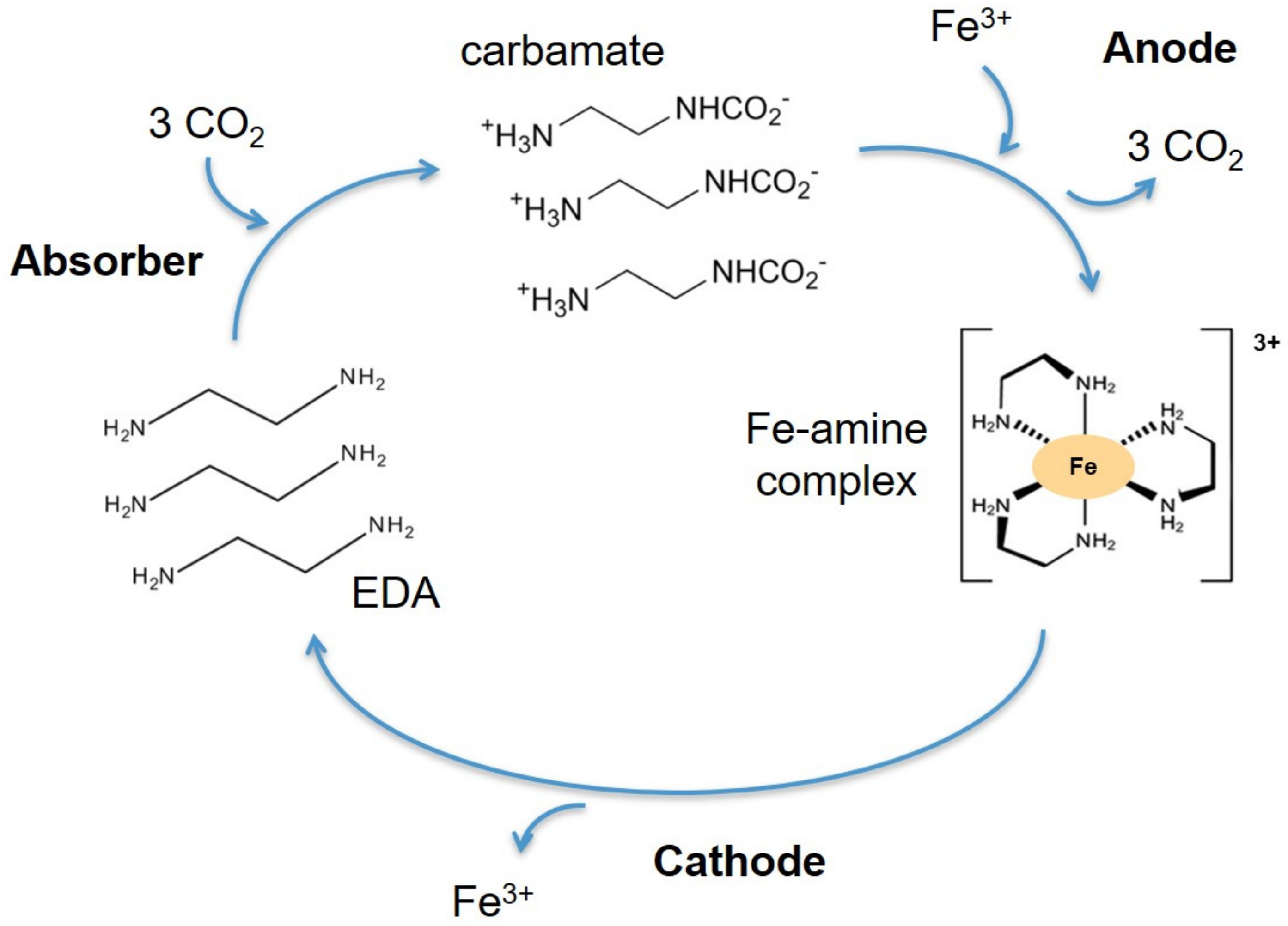
3.1. CO2 Mechanism
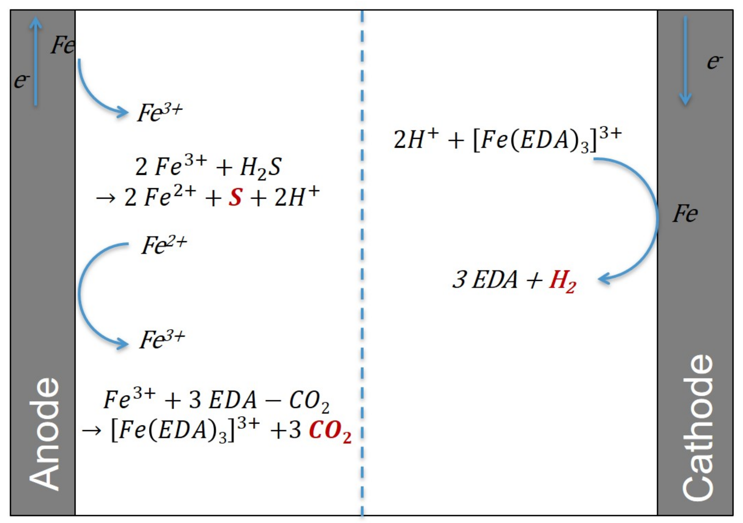
3.2. H2S Mechanism
3.3. Reasons for Selecting the Fe3+/Fe2+ Couple
3.3.1. The Advantages of the Fe3+/Fe2+ Couple
3.3.2. The Disadvantages of the Fe3+/Fe2+ Couple
3.4. Basic Technoeconomical Study
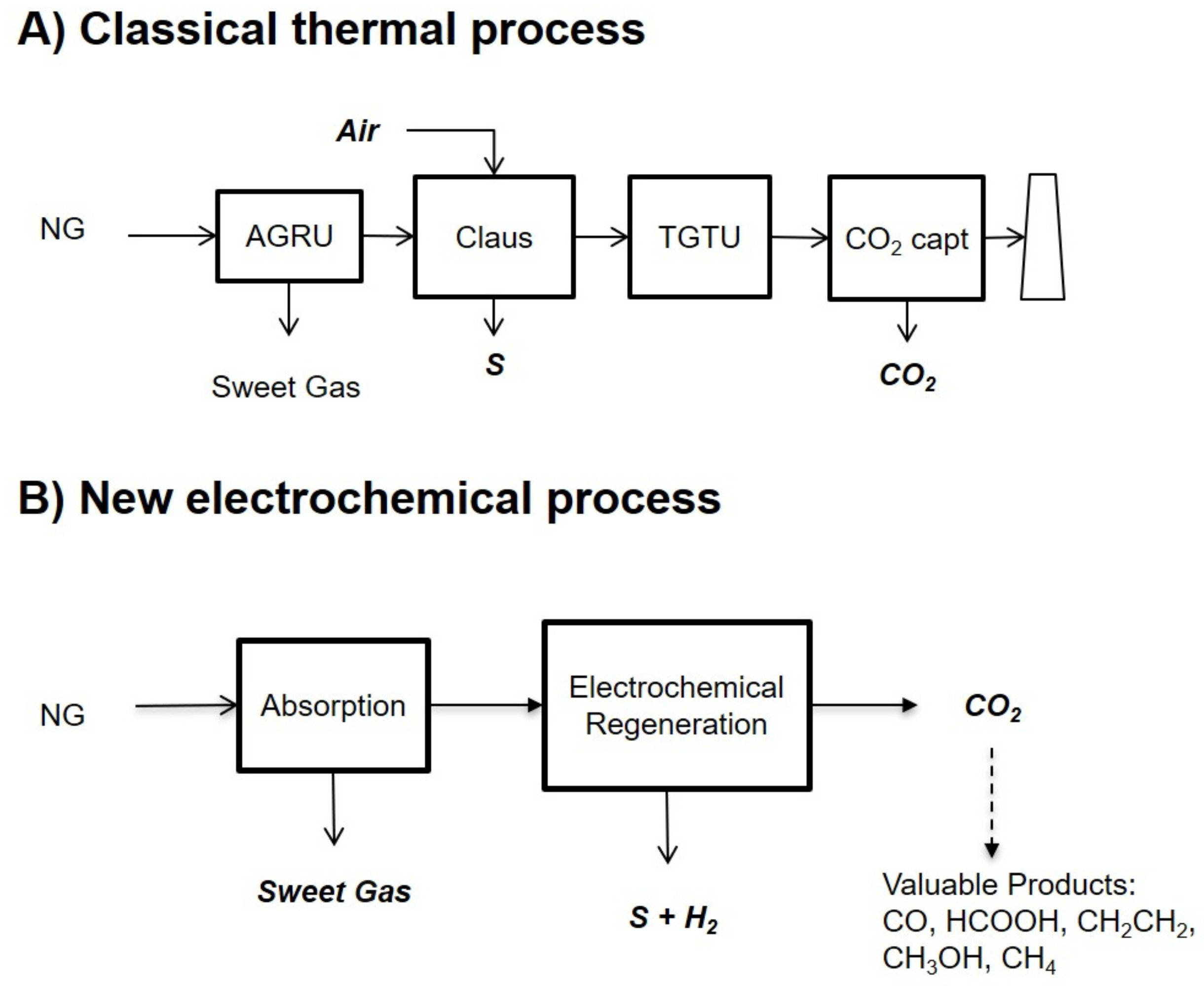
3.4.1. Comparison between Electrochemical and Thermal Regeneration with a Model Case from the Middle East
Base Case AGRU/SRU
Electrochemical Regeneration
Methane Equivalent
3.4.2. Industrial Interest and Major Challenges of the Technology
3.5. Future Research Directions
4. Conclusions
Author Contributions
Funding
Institutional Review Board Statement
Informed Consent Statement
Acknowledgments
Conflicts of Interest
References
- Burgers, W.F.J.; Northrop, P.S.; Kheshgi, H.S.; Valencia, J.A. Worldwide development potential for sour gas. Energy Procedia 2011, 4, 2178–2184. [Google Scholar] [CrossRef] [Green Version]
- Okoro, O.V.; Sun, Z. Desulphurization of biogas: A systematic qualitative and economic-based quantitative review of alternative strategies. Chemengineering 2019, 3, 76. [Google Scholar] [CrossRef] [Green Version]
- Georgiadis, A.G.; Charisiou, N.D.; Goula, M.A. Removal of hydrogen sulfide from various industrial gases: A review of the most promising adsorbing materials. Catalysts 2020, 10, 521. [Google Scholar] [CrossRef]
- Orlov, A.A.; Marcou, G.; Horvath, D.; Cabodevilla, A.E.; Varnek, A.; de Meyer, F. Computer-aided design of new physical solvents for hydrogen sulfide absorption. Ind. Eng. Chem. Res. 2021, 60, 8588–8596. [Google Scholar] [CrossRef]
- Bui, M.; Adjiman, C.S.; Bardow, A.; Boston, A.; Brown, S.; Fennell, P.S.; Fuss, S.; Galindo, A.; Hackett, L.A.; Hallett, J.P.; et al. Carbon capture and storage (CCS): The way forward. Energy Environ. Sci. 2018, 11, 1062–1176. [Google Scholar]
- Rochelle, G. Amine Scrubbing for CO2 Capture. Science 2009, 325, 1652–1654. [Google Scholar] [CrossRef]
- Kohl, A.L.; Nielsen, R. Gas Purification, 5th ed.; Gulf Professional Publishing: Houston, TX, USA, 1997. [Google Scholar]
- Versteeg, G.F.; van Swaaij, W.P.M. On the kinetics between CO2 and alkanolamines both in aqueous and non-aqueous solutions –I. Primary and secondary amines. Chem. Eng. Sci. 1988, 43, 573–585. [Google Scholar] [CrossRef] [Green Version]
- Eow, J.S. Recovery of sulfur from sour acid gas: A review of the technology. Environ. Prog. Sustain. Energy 2004, 21, 143–162. [Google Scholar] [CrossRef]
- Shah, M.S.; Tsapatsis, M.; Siepmann, J.I. Hydrogen sulfide capture: From absorption in polar liquids to oxide, zeolite, and metal-organic framework adsorbents and membranes. Chem. Rev. 2017, 117, 9755–9803. [Google Scholar] [CrossRef]
- Stern, M.C.; Simeon, F.; Herzog, H.; Hatton, T.A. Post-combustion carbon dioxide capture using electrochemically mediated amine regeneration. Energy Environ. Sci. 2013, 6, 2505–2517. [Google Scholar] [CrossRef] [Green Version]
- Eltayeb, A.O.; Stern, M.C.; Herzog, H.; Hatton, T.A. Energetics of electrochemically mediated amine regeneration. Energy Procedia 2014, 63, 595–604. [Google Scholar] [CrossRef] [Green Version]
- Shaw, R.A.; Hatton, T.A. Electrochemical CO2 capture thermodynamics. Int. J. Greenh. Gas Control 2020, 95, 102878. [Google Scholar] [CrossRef]
- Rahimi, M.; Diederichsen, K.M.; Ozbek, N.; Wang, M.; Choi, W.; Hatton, T.A. An electrochemically mediated amine regeneration process with a mixed absorbent for post-combustion CO2 capture. Environ. Sci. Technol. 2020, 54, 8999–9007. [Google Scholar] [CrossRef]
- Liu, Y.; Ye, H.Z.; Diederichsen, K.M.; Van Voorhis, T.; Hatton, T.A. Electrochemically mediated carbon dioxide separation with quinone chemistry in salt-concentrated aqueous media. Nat. Commun. 2020, 11, 2278. [Google Scholar] [CrossRef]
- Wang, M.; Rahini, M.; Kumar, A.; Hariharan, S.; Choi, W.; Hatton, T.A. Flue gas CO2 capture via electrochemically mediated amine regeneration: System design and performance. Appl. Energy 2019, 255, 113879. [Google Scholar] [CrossRef]
- Wang, M.; Hatton, T.A. Flue gas CO2 capture via electrochemically mediated amine regeneration: Desorption unit design and analysis. Ind. Eng. Chem. Res. 2020, 59, 10120–10129. [Google Scholar] [CrossRef]
- Voskian, S.; Brown, P.; Halliday, C.; Rajczykowski, K.; Hatton, T.A. Amine-based ionic liquid for CO2 capture and electrochemical or thermal regeneration. Sustain. Chem. Eng. 2020, 8, 8356–8361. [Google Scholar] [CrossRef]
- Stern, M.C. Electrochemically-Mediated Amine Regeneration for Carbon Dioxide Separations. Ph.D. Thesis, Massachusetts Institute of Technology, Cambridge, MA, USA, 2013. [Google Scholar]
- Hatton, T.A. Electrochemically-Mediated Sorbent Regeneration in CO2 Scrubbing Process. Final Report DOE Project DE-FE0026489; U.S. Department of Energy: Washington, DC, USA, 2021. [Google Scholar]
- Iliuta, I.; Larachi, F. Concept of bifunctional redox iron-chelate process for H2S removal in pulp and paper atmospheric emissions. ChemEngSci 2013, 58, 5305–5314. [Google Scholar] [CrossRef]
- Neumann, D.W.; Lynn, S. Oxidative absorption of H2S and O2 by iron chelate solutions. AIChE J. 1984, 30, 62–69. [Google Scholar] [CrossRef]
- Wubbs, H.J.; Beenackers, A.A.C.M. Kinetics of H2S absorption into aqueous ferric solutions of EDTA and HEDTA. AIChE J. 1994, 40, 433–444. [Google Scholar] [CrossRef]
- Demminck, J.F.; Beenackers, A.A.C.M. Gas desulfurization with ferric chelates of EDTA and HEDTA: New model for the oxidative absorption of hydrogen sulfide. Ind. Eng. Chem. Res. 1998, 37, 1444–1453. [Google Scholar] [CrossRef]
- Lefrou, C.; Fabry, P.; Poignet, J.-C. Electrochemistry, the Basics with Examples; Springer: Berlin/Heidelberg, Germany, 2012. [Google Scholar]
- Zhou, S.; Chen, X.; Nguyen, T.; Voice, A.K.; Rochelle, G.T. Aqueous ethylenediamine for CO2 capture. ChemSusChem 2010, 3, 913–918. [Google Scholar] [CrossRef]
- Weiland, R.H.; Trass, O. Absorption of carbon dioxide in ethylenediamine solutions i. absorption kinetics and equilibrium. Can. J. Chem. Eng. 1971, 49, 767–772. [Google Scholar] [CrossRef]
- Sada, E.; Kumazawa, H.; Butt, M.A. Absorption of carbon dioxide into aqueous solutions of ethylenediamine: Effect of interfacial turbulence. Chem. Eng. J. 1977, 13, 213–217. [Google Scholar] [CrossRef]


| Mw (gmol−1) | ρ (gL−1) à 25 °C | w (%) | X (%) | C (molL−1) | |
|---|---|---|---|---|---|
| H2O | 18 | 1000 | 70 | 89 | 37.6 |
| EDA | 60 | 900 | 30 | 11 | 4.8 |
| pKs (298 K) | pKs (323 K) | |
|---|---|---|
| Fe(OH)2 | 15.4 | 14.8 |
| Fe(OH)3 | 38.2 | 36.8 |
| Fe3+ + | 3 EDA = | Fe(EDA)33+ | |
|---|---|---|---|
| Initial | 1 | 3.1 | 0 |
| 1 − x | 3.1 − 3x | x | |
| Final | ε3 | 0.1 | 1 |
| (In MW) | SRU | AGRU | Total |
|---|---|---|---|
| Fuel | 126 | - | - |
| HP steam | −22.5 | - | - |
| LP steam | −27.6 | 106.2 | - |
| Total | 75.9 | 106.2 | 182.1 |
| Without CO2 Recovery | With CO2 Recovery | Electrochemical Regeneration | |
|---|---|---|---|
| Energy OPEX (MW) | 182 | 319 | 122 |
| Efficiency | 85% | 85% | 60% |
| Fuel equivalent (MW) | 214 | 375 | 203 |
Publisher’s Note: MDPI stays neutral with regard to jurisdictional claims in published maps and institutional affiliations. |
© 2021 by the authors. Licensee MDPI, Basel, Switzerland. This article is an open access article distributed under the terms and conditions of the Creative Commons Attribution (CC BY) license (https://creativecommons.org/licenses/by/4.0/).
Share and Cite
de Meyer, F.; Bignaud, C.; Poulain, B. Selective Electrochemical Regeneration of Aqueous Amine Solutions to Capture CO2 and to Convert H2S into Hydrogen and Solid Sulfur. Appl. Sci. 2021, 11, 9851. https://doi.org/10.3390/app11219851
de Meyer F, Bignaud C, Poulain B. Selective Electrochemical Regeneration of Aqueous Amine Solutions to Capture CO2 and to Convert H2S into Hydrogen and Solid Sulfur. Applied Sciences. 2021; 11(21):9851. https://doi.org/10.3390/app11219851
Chicago/Turabian Stylede Meyer, Frédérick, Charles Bignaud, and Bénédicte Poulain. 2021. "Selective Electrochemical Regeneration of Aqueous Amine Solutions to Capture CO2 and to Convert H2S into Hydrogen and Solid Sulfur" Applied Sciences 11, no. 21: 9851. https://doi.org/10.3390/app11219851
APA Stylede Meyer, F., Bignaud, C., & Poulain, B. (2021). Selective Electrochemical Regeneration of Aqueous Amine Solutions to Capture CO2 and to Convert H2S into Hydrogen and Solid Sulfur. Applied Sciences, 11(21), 9851. https://doi.org/10.3390/app11219851