Abstract
Mass customization aims to meet individual requirements and, therefore, is one way to attract and retain customers—a key challenge in the design industry. The increase in design automation has offered new opportunities to design customized products at high speed in a way that is cost equivalent to mass production. Design automation is built upon the reuse of product and process knowledge. Ontologies have proven to be a feasible, highly aggregated knowledge representation in engineering design. While product and process knowledge from other lifecycle phases are represented in multiple approaches, the design process of the product as well as the adaption process of product variants is missing, causing breakpoints or additional iterations in design automation. Therefore, suitable knowledge representation tailored to design automation is still missing. Accordingly, this contribution proposes a novel knowledge representation approach to enable design automation for mass customization. Methodically, this novel approach uses semantic enrichment of CAD environments to automatically deduce information about a design task, design rationale, and design process represented by a formal ontology. The integration of the design process significantly differentiates the approach from previous ones. The feasibility of the approach is demonstrated by a bike crank customization process.
1. Introduction
The engineering design industry is constantly being challenged by the need to attract and retain customers, the need to maintain and increase its market share and profitability, and the need to meet the requirements of diverse communities [1]. To fulfill customer requirements in the best possible way, these requirements are integrated into the design process, leading to individualized products. To use this possibility beneficially and to increase the market share and profitability of the industry, mass customization (MC) has become a major trend [2]. Following Ramani et al. [3], MC is the process of designing and manufacturing products that are customized to meet the user’s needs but at speeds and costs equivalent to those used for mass production. MC heavily relies on quick reactions to customer needs, forcing a shift of routine tasks from the human designer to comparably fast automated support tools by reusing related product and process knowledge [4]. Commonly, knowledge-based engineering (KBE) applications focus on the automation of a single specific design task that modifies design characteristics to fulfill at least one design rationale by reusing product knowledge [5]. This reduces the engineering time spent on one task, but it leads to standalone solutions for particular tasks [6].
When chaining design tasks to a design automation (DA) process, the high number of repetitive tasks in a MC process need to interlock smoothly, as otherwise, additional effort is required for each transfer from one to the next. As stated by Camba et al. [7], there is a lack of tools to accurately assess changes in design parameters, and the design of a model that represents changes from a process perspective is still considered future work. To track design parameters and their changes during the design process, it has become necessary to consider design tasks’ constraints and sequences as knowledge to enable DA of design processes instead of standalone tasks. This demands the integration of process knowledge, since within a product-oriented approach, a particular state within a design process is described by facts about the geometrical configuration and potentially that can be enriched by design rationale that describes why this configuration was chosen. However, the adaptation process itself is not covered within the rationale, which refers to the process knowledge in engineering design. Hypothetically, a certain design task could modifywhich characteristics are necessary, allowing would allow more flawless DA. In the context of a particular MC process, this information provides knowledge about the underlying design process and, if processable, would enable a shift in DA from single design tasks to whole design processes. For innovative design processes, building knowledge representation is very ambitious. However, in comparison with other design processes, MC processes are lrather straightforward. Accordingly, this contribution proposes a novel model and knowledge representation to determine how knowledge about the design process should be represented to enable design automation for mass customization design processes. Knowledge representation should meet the following requirements: First, knowledge representation needs to be human and computer processable [8,9,10]. Second, knowledge representation needs to emphasize interoperability with existing knowledge representations in engineering design, and third, knowledge representation should obey the minimal commitment [10,11]. Fourth, the instantiation of knowledge representation needs to be automated to handle modern products with a multitude of design parameters [12,13]. Fifth, user interaction has to take place in a usual design environment to lessen the initial hurdle for design engineers.
The paper is structured as follows: First, Section 2 highlights the scientific background and analyzes related approaches. Subsequently, Section 3 presents the model and knowledge representation. The model specifies the possibilities and restrictions associated with MC processes in human processable form and, therefore, defines necessary concepts for MC design processes. Building on this, SeEDMC (Semantic integration for Engineering Design in Mass Customization) is the knowledge representation of this model, and it allows DA applications to process the model. SeEDMC expands the SeED approach. It processes geometric information only using the design process and corresponding concepts and axioms [14]. Within this important extension, semantic descriptions are used to integrate different aspects (e.g., geometry, functions, principles) of engineering design semantically, which is vital for design automation in mass customization. In order to probe their feasibility, the method is demonstrated using an exemplary mass customization process in Section 4. Finally, Section 5 discusses the method and its application, reveals the current limitations, and presents approaches for further developments.
2. Background
The reuse of knowledge in CAD systems has evolved massively, and CAD files have become far more than pictorial and virtual representations of structural design [15]. First, parametrization has allowed the integration of algorithms, like mathematical equations or more difficult constraints [16,17]. Second, the integration of geometric features and knowledge-based design has embedded a variety of knowledge representations into the CAD environment, leading to the automatic generation of small parts of the CAD model (e.g., the hole feature). The process of inter-relating information from different sources is known as design integration. In this case, the design is in the center of this process and, therefore, it is enriched by relevant information, e.g., design rationale. Recently, product data technology has been developed to support the capture of product information throughout its lifecycle in computer-interpretable form [18]. Following the explosion of data sources, CAD environments have, on the one hand, the chance to become comprehensive applications for the reuse of knowledge, while on the other hand, they must solve the task of providing knowledge as decision support for designers and for design automation at the right stage of the design process, which has become increasingly crucial [19]. Therefore, one of the major concepts for future CAD systems is to integrate design knowledge representations that are flexible and adaptable for a range of useful engineering design knowledge [20]. The link between CAD systems and knowledge representations can be established by annotations that explicitly represent the design intent [21]. Camba and Contero [22] investigated the ablility to facilitate the reusability of CAD models through the use of annotations that store information about virtual products, like the design intent. For knowledge representation, design ontologies have become a vital solution.
2.1. Terms and Definitions
A Knowledge Representation (KR) is a branch of Artificial Intelligence (AI) that deals with the question of how knowledge can be represented in such a way that a machine can draw conclusions from it, derive further knowledge, or find a solution to a given problem [23,24].
Following the definition presented by Gruber et al. [25], an Ontology is an explicit specification of a conceptualization, which means that ontology provides well-defined concepts, relations, and other objects that specify the knowledge of a domain in an explicit way. Within knowledge-based applications, ontologies aim to overcome misinterpretation and thus optimize communication between humans and machines as well as optimizing interhuman and intermachine communication [26].
Design Automation (DA) is an evolutionary step in computer-aided engineering achieved by knowledge-based engineering, which represents a merging of object-oriented programming, artificial intelligence, and computer-aided design technologies [4,27]. Generally, design automation in engineering design requires deep insight into the design process to be able to capture and formalize the principles in the design domain [28].
Mass Customization (MC) is the process of designing and manufacturing products that are customized to meet the user’s needs but at speeds and costs equivalent to those used in mass production [3]. Customization in the mechanical domain is a sequence of design adaptations, which are defined as modifications of the sizing, shaping, and positioning of geometric elements as well as the modification of material or manufacturing specifications [29].
Design Rationale (DR) is considered important knowledge for the future generation of product development systems [30]. In general, it refers to the explanation of why an artifact is designed the way it is [31]. Without a careful record of design rationale, a significant increase in time and effort is necessary to search for relevant answers [5].
2.2. Related Work
The use of ontologies in the domain of engineering design and, in particular, regarding CAD systems was presented in a recent review of ontology-focused feature modeling technology by Sanfilippo and Borgo [32]. As one result of the analyses, features regarding manufacturing information are abundant, while support for function integration in terms of pictorial design intent is surprisingly under-represented. In this domain, Erden et al. [33] and Garbacz et al. [34] reviewed ontological representations of design intent from different perspectives. Garbacz et al. [34] proposed the formalization of two main understandings of design intent in engineering. One is the Functional Basis approach, defined by Stone and Wood [35], where functions are understood as operations on flows performed by artifacts. This description was integrated with process ontologies in Erden et al. [33]. The second refers to the Functional Representation approach developed by Chandrasekaran [36], which defines functions as behaviors of artifacts (Functional concept ontologies in Erden et al. [33]). From these reviews, there are three approaches that share the idea of a CAD-embedded ontological knowledge representation for design characteristics and intent as domain knowledge.
DANE and SBF models: DANE (Design by Analogy to Nature Engine) is the latest application that reuses bionic knowledge for future product generations based on Structure-Behavior-Function (SBF) models according to [37]. Structure is represented in terms of components, the substances contained in the components, and connections among the components. Function is represented as a schema that specifies its preconditions and postconditions. The function schema contains a reference to the behavior that accomplishes the function. Behavior is represented as a sequence of states and transitions between them [37]. The SBF model is used as knowledge representation for a number of knowledge applications (e.g., KRITIK [38], IDEAL [39], ARCHYTAS [40], DANE [41]).
OntoSTEP: The Product Data Exchange format STEP (Standard for Exchange of Product model data), which describes product data models in application protocols (APs), allows engineering data to be interchanged [42]. The first concept for an ontology, which is used for the exchange of product data, was published in 2005 with Product Semantic Representation Language (PSRL) [43]. The idea was further developed, and additional APs were integrated [44,45]. OntoSTEP is the representation of STEP product models in Web Ontology Language. It was introduced in 2009 and is continuously being expanded [46,47].
Semantic Alliance: Semantic Alliance is the core component of multiple approaches. It was first published in 2009 and further developed until 2013 [48,49]. In principle, semantic information is annotated to the CAD in order to verify, at an early stage, whether product properties can be guaranteed. Three main components have been described: a knowledge base called Planetary, an interface to the CAD environment called Alex, and an interoperability component called Sally. All three components form the Semantic Alliance. The semantic information is mostly document-based. It is modeled with the help of XML-based markup languages in a machine-readable and machine-processable format [50].
None of the approaches or methods found were developed to explicitly support design automation. Therefore, each approach lacks different requirements stated in the introduction that hinder or even prevent its use for design automation. Most importantly, they lack the ability to reuse the design process as knowledge. Although the SBF model offers the possibility to represent processes with the help of states and transitions, these are only used to represent product behaviour after development. Furthermore, the analyzed approaches support the conceptualization rather than the design of the product. OntoSTEP offers the possibility to integrate process models, but these are used to consider other processes, such as manufacturing, in product development. The Semantic Alliance offers a bidirectional interface between knowledge representation and the CAD model, but no processes or temporal state sequences are taken into account in the annotated documents. From this review, we conclude that the capture of design intent and design rationale can be undertaken by multiple approaches but, in combination with a representation of the design process, bidirectional CAD integration is still missing.
3. Method
It can be deduced from related work that human and computer processable knowledge representation, including a detailed design process, to enable the reuse of design process knowledge in DA applications does not exist at present. To achieve this, we present a novel approach. An overview is shown in Figure 1. First, a model for the MC process is presented (1 in Figure 1), which defines the required concepts for human and computer processable knowledge representation (SeEDMC, 2 in Figure 1). SeEDMC defines the generic intensional knowledge, the meanings of the used terms, about the MC process and, thus, enables DA applications to process the sequences, constraints and design intents of MC processes. Assertional knowledge depends on the MC process being handled. For instantiation, three data sources are gathered from the initial development process, which has to be completed before the MC process: first, the design characteristics; second, the solution principles; and, third, the modular structure containing the requirements. While the design characteristics and solution principles are handled automatically, the modular structure requires interaction with the product developers. Thus, SeEDMC is integrated into the design environment with the help of an annotation scheme (3 in Figure 1). With its support, product developers can define process models, which are then automatically loaded into SeEDMC by the wrapper (4 in Figure 1). Since SeEDMC’s scope is the representation of the design process, other knowledge representations that map other knowledge sources are needed. For this purpose, we introduce a mapping scheme (5 in Figure 1).
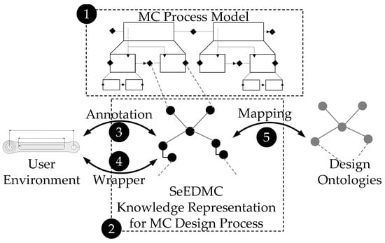
Figure 1.
Illustration of the approach consisting of the model used for the MC process (1), its knowledge representation (2, SeEDMC), its integration into the development environment via an annotation scheme (3) and a wrapper (4), as well as the integration into existing knowledge representations with the help of a mapping scheme (5).
3.1. Model of the Design Process for MC
Despite the different specifications of MC processes across various products and industries, their design processes can be reduced to common characteristics. With an MC process, it can be assumed that the initial design process has already been completed. Accordingly, the product has already been fully developed at least once and, therefore, the MC is either a revision, variant, or adaptation design [51]. A new design and the associated innovative sub-processes do not have to be taken into account by the model. Of the design types mentioned, adaptation design has the widest scope for modifications. However, the principle solution is fixed and an individual product is generated by modification of the product’s characteristics. These restrictions are the framework of the model, which has a chronological and a hierarchical axis. On the chronological axis, the temporal sequence of States and Transitions of the MC process is modeled. A State is a representation or snapshot in time of all definable characteristics of the product. For the geometric domain, examples of modifiable characteristics include geometric dimensions, characteristics of tolerances, or material specifications [29]. A Transition is a modification of characteristics. At the highest level of the hierarchy, the MC process describes a Transition between an undesired Initial State and a desired Terminal State. The starting point of the MC Design Process is the standard or initial product. The Terminal State is the individualized product. The top level of the hierarchy is shown in Figure 2.

Figure 2.
Illustration of the MC Design Process model’s top level, including a hierarchical and a chronological axis to guide the process from an undesired initial State to a desired terminal State by at least one Transition.
Transitions are further specified by the purpose (explanation of why) they fulfill. At the highest level of the hierarchy, this purpose is the individual requirements of the product to be customized (see Figure 2). With regard to the research question, it is crucial to be able to model when and which requirements are fulfilled explicitly. For this purpose, the hierarchical axis is introduced in addition to the chronological axis. Beforehand, the Design Rationale is defined as a general interface for every Transition’s purpose. In order to specify this more precisely, adaptation designs are considered according to [51]. In general, requirements are fulfilled by functions. For this purpose, (partial) functions are transferred into solution principles and their modular structures. These are detailed by designing the characteristics. From these characteristics, the product’s behavior can be matched with the requirements. For adaptation design, the principle solution (solution principles and modular structure) is fixed, and only the design characteristics are modified. Since the MC Design Process, in the most innovative case, is comparable to an adaptation design and the initial design process is accomplished beforehand, a principle solution (solution principles and modular structure) exists and can be utilized to specify the Design Rationale of the Transitions. When a Transition can be directly described by a solution principle, the Transition is specified as a Design Task. Otherwise, the modular structure is used to describe the Transition as a subordinated Design Process. As a demonstration, Figure 3 illustrates a model of a hypothetical MC process with three levels. On the top level, the MC Process is related to the individual requirements. As this MC Process has more than one solution principle to fulfill, the requirements are passed onto the first suboriented level. There, according to the hypothetical modular structure, one portion of the requirements is passed onto the lowest level. The other portion is fulfilled by a Design Task. On the lowest level, two Design Tasks model the solution principles which fulfill the remaining requirements. For suboriented Design Processes, the States at the beginning and end of each Transition are passed onto the lower level.
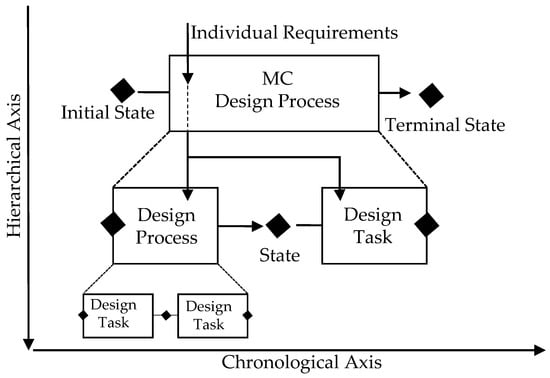
Figure 3.
Illustration of a hypothetical MC Design Process with three levels.
Summary of Concepts: the model defines the Design Process as Transitions between States. A State is the representation of all design characteristics at a defined point in time. If a State has no prior Transition, it is called the Initial State. If a State has no subsequent Transition, it is called the Terminal State. A Transition has a Design Rationale and is either a Design Task or a Design Process. A Design Task has exactly one solution principle. A solution principle satisfies the Design Rationale according to the principle solution. A Design Process has Input and Output Rationales which define relations according to the modular structure. A MC Design Process has at least one Transition.
3.2. Knowledge Representation of the Design Process for MC
In order to obtain computer- and human-processable knowledge representation, the superordinate representation type is an ontology, as this is characterized by high flexibility, reusability, and adaptability [52,53]. Following the latest design criteria defined by Gruber [11], whereby an ontology should require minimal ontological commitment, we claim only a few axioms (see Table 1) about the following concepts. Thus, those concepts can be specialized for certain MC processes: Transition, State, Beginning State, Objective State, Initial State, Terminal State, Design Parameter, Design Process, Design Task, Design Rationale, Requirement, and Solution Principle. In addition, generally accepted concepts are applied e.g., Type, Value, and Unit. The concepts of States are further extended by the axioms demonstrated in Table 1.

Table 1.
Axioms for States.
As the various types of states demonstrated in Table 1 define snapshots of the product on the chronological axis, Transitions specify their sequences in the process model and their design intent as well as hierarchical relations by Design Rationale. The concepts of Transitions are further extended by the axioms demonstrated in Table 2.
Table 2.
Axioms for Transitions.
The Solution Principle excels as it contains exactly one source file. This source file represents the relationships between the Design Rationale (requirements) and Design Parameters in the form of logical, statistical, or mathematical mapping:
Therefore, a Solution Principle has forms of Design Rationale as inputs and Design Parameters as outputs. Depending on the considered domain of interest, solution principles differ in their types of representation. In many cases, markup languages or scripts are sufficient. Typically, principled solutions are stored and managed in catalogs [54].
The axioms shown in Table 1 and Table 2 were designed to represent the model described in Section 3.1. In a hypothetical MC process, at least one Design Parameter is adjusted due to individual requirements. The requirement modification can only be quantitative. New additional requirements cannot be taken into account, as otherwise the principle solution would have to be changed, and this would no longer be within the capabilities and scope of the model. Accordingly, there is at least one Transition and two States. If only these exist, the State prior to the Transition is automatically identified as the Initial State, since it is never used as an Objective State of any Transition. Similarly, the State subsequent to the Transition is the Terminal State. The individual requirement modifications specify the Design Rationale of the Transition. If this modification can be implemented by a single solution principle, the Transition is a Design Task that can perform the MC Process. No outputs for subordinate Transitions are required. If this is not the case, it is, by definition, a Design Process, which is used to reflect at least part of the known product’s modular structure. Consequently, the Design Process has at least two outputs, which split the Design Rationale from the input among the hierarchically subordinate Transitions. By splitting the Design Rationale into more hierarchical levels according to the modular structure until Design Tasks implement the modifications following their solution principle and taking the sequence of Transitions and States into account, SeEDMC can represent why, when, and which design characteristics are changed in MC Processes. Reflecting the research question, this is the intentional knowledge that enables design automation of the whole MC process, provided that every design task is automated.
3.3. Annotation Scheme and Process
As the concepts and axioms define the intensional knowlegde, the assertional knowledge specifies individual MC processes. To avoid media discontinuity and transfer errors, the instantiation is integrated into the environment of the product developers. Thus, annotation schemes are used to link the design environment with SeEDMC. They are used to enable annotations on design characteristics that are Design Parameters, e.g., in the mechanical domain, the extrusion length and in the CAD environment, as States of the MC process. Concepts for Transitions consist of two States. The content of this annotation is a Transition and, thus, is completed with, if necessary, Output Design Rationale. The annotation schemes exploit the Web Annotation Data Model [55], which aims to provide a standard description model and format to enable the sharing of annotations between systems. This is demonstrated in Figure 4.
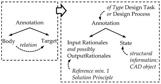
Figure 4.
Web Annotation Data Model (left) and transferred Annotation Model for SeEDMC (right).
User interactions and, therefore, annotations take place in the domain specific product development environment. The starting point is the virtual product (e.g., the CAD model for the mechanical domain) If no MC process has been formally described and annotated to the virtual product, a new MC process is instantiated (Step 1 in Figure 5). In this case, the current state of the product automatically defines the initial state of the process. First, all individual requirements are instantiated manually or imported from a requirements list. Since a new MC process consists of at least one Transition, a Transition is added. The requirements automatically state the Input Rationale of this Transition. The user must specify whether this is a Design Task or a Design Process (Step 2 in Figure 5).
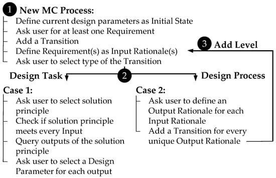
Figure 5.
Illustration of the Annotation Process for SeEDMC.
- Case 1:
If it is a Design Task, the user is asked to add the corresponding Solution Principle from the catalog. As this selection is only valid if all forms of Input Rationale for the Transition can be assigned to the inputs of the Solution Principle, the associated source file is checked. If the selection is valid, the current state is the Beginning State of this Transition, and the outputs of the source file are queried. The user is asked to select a Design Parameter in the development environment for each output. According to Equation (1), the Input Rationale of the Transition maps the Design Parameters as Objective States of the Transition. As a result, the Transition is completed and annotated to these Design Parameters.
- Case 2:
If the Transition is a Design Process, the splitting of the forms of Design Rationale is specified by the user according to the following steps. With the selection of Design Process, the user is asked to define a Output Rationale for each Input Rationale of the Transition. Multiple forms of Input Rationale may have the same Output Rationale. However, there have to be at least two unique types of Output Rationale. The order of the unique types of Output Rationale must be observed, as this defines the sequence of Transitions at the subordinate level. A Transition is automatically instantiated for each form of Output Rationale at the subordinate level (Step 3 in Figure 5).
For each Transition, the annotation process is repeated until all Requirements from the top level are met by the Input Rationale of a Design Task.
3.4. Wrapper for Automated Instantiation
To complete the instantiation, the annotated MC process is automatically loaded from the development environment into the knowledge representation. In most development environments, the stored information can be extracted via an API. Particularly, in the mechanical domain, the SeED approach is used [14]. As stated previously, states define snapshots of the product at certain points in time. Therefore, states are expressed by the values of the geometric parameters at that point. By iterating the model tree of the product, the all design parameters are queried in the environment and instantiated with the help of a mapping scheme. For example, a cube in a CAD environment is usually designed by using an extrusion feature. In Figure 6, this feature is defined by a sketch and an extrusion length. Iterating the model tree, the wrapper will start at the top level which, in this case, is the extrusion feature extracting the ID, the reference-ID, the location, and so forth. As other geometric objects are related to the extrusion, e.g., the sketch, the wrapper steps into the sketch and extract the geometic information provided there. A complete iteration provides a snapshot of the product. Since geometric parameters are linked to the Transitions via the annotation scheme, they are transferred accordingly.
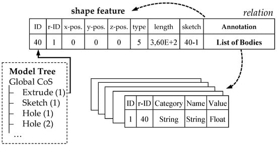
Figure 6.
Illustration of the extraction of structural data (e.g., shape feature) based on [14] and expansion for the extraction of annotated semantic data by the use of the annotation scheme.
3.5. Ontology Alignment
An ontological representation allows connections to other vocabularies, a process known as ontology alignment or merging [56], if parts of different ontologies correspond to each other. The SeEDMC ontology, therefore, can be aligned with other potential existing ontologies. Hoekstra [12] stresses, that the alignment and merging of ontologies can lead to alternated commitment of the underlying assumptions of the merged ontologies. To overcome a fundamental violation of the ontological commitment of our SeEDMC model, a few hints on potential extensions are given and illustrated in Figure 7. Since requirements are strongly connected with the Input Rationale for a Design Task executed in a solution principle, only quantitative requirements can be used in the SeEDMC process.
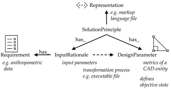
Figure 7.
Illustration of the alignment of SeEDMC’s concepts to other knowledge representations.
However, if an ontology exists for requirements engineering, the class Requirement can be hierarchically extended with the SubClassOf axioms, to further classify the requirements model within a use case, allowing the integration of this ontology. Therefore, the requirements should be sorted into quantitative (and therefore executable) requirements and qualitative ones. Moreover, the Design Parameter class, which defines concrete metrics from CAD entities, can also be extended by the SubClassOf axioms to classify different parameters (e.g., length, angle), if necessary. The representation of solution principles, here, is executable scripts that thus share the same representation. If design tasks, expressed as solution principles, have different formats, this can be stated by extending the Representation class with a SubClassOf axiom and aligning metadata for those formats.
4. Application
To probe the feasibility of the SeEDMC, this section first demonstrates the setup of a model and knowledge representation using the method described and, second, shows its application for the process of automatically generated product generation for individualized customer data.
4.1. Use Case
Most parts of common bicycles are mass produced. This results in fixed sizes for, e.g., bike frames, handlebars, and cranks. On the one hand, this leads to a cost-efficient production value. It results, on the other hand, in reduced flexibility to optimize bicycles for customers. The benefits of an optimal fit between the anthropometrics of the rider and the bike range from better muscle activation [57], better oxygen uptake [58], and higher pedal forces [59] to smaller knee joint forces [60]. The latter is the most important, because it correlates with the likelihood of nonaccidental injuries in bike riding [61]. To limit the complexity of the use case, the focus is on customer anthropometrics affecting the bike cranks. Note that the length of the bike cranks has the second largest effect on the bike fit after the distance between the saddle and handlebars [61]. Additionally, lightweight design and legal standards are further considered. In summary, the individual requirements are specified by the anthropometrics (length of the customer’s femur, fibula, and foot as well as their flexibility in terms of joint angles), in combination with minimal weight while still fulfilling the standards according to DIN EN ISO 4210-8 [62]. In the initial development of the bike crank, these requirements are fulfilled by two solution principles. First, the crank length is adapted to the anthropometric requirements. Second, further design parameters are adapted (crank depth, as well as the length, width and depth of the slot) in order to achieve the lowest possible mass with sufficient stiffness. In terms of the sequence, it is necessary to adapt the crank length first, because the crank length affects the stiffness of the crank.
4.2. MC Process Model
The model describes an MC process from a standard bike crank to a custom bike crank and is demonstrated in Figure 8. On the top level, the individual requirements are the Input Rationale for the Transition between the Initial State and the Terminal State. As there is no solution principle that cannot fulfill all requirements at once, the Transition has to be the Design Process, and the Input Rationale is split into at least two types of Output Rationale. According to the initial development process used to produce the crank, exactly two solution principles are necessary. Therefore, on the second level, the Design Rationale is met with two Transitions. The Initial State is the Beginning State of the Design Process and links to the first Design Task. The Terminal State is the Objective State of the Design Process and the second Design Task. Both Design Tasks on the second level fulfill their Design Rationale, as they define relations between the Input Rationale and the Design Parameters by solution principles. By definition, these are Design Tasks and, for convenience, they are titled Design Task 1 for the anthropometric requirements and Design Task 2 for the requirements related to lightweight design. For the general method, it is possible to use any source file that is able to represent a relation between input and output variables and that can be organized in a catalog. For this particular customization process, the solution principles are implemented as Python scripts (see Appendix A). Each script defines a class member of the class solution principle. Each solution principle object has at least one input, at least one output, and one function that returns the outputs for given inputs. The solution principle of the anthropometric Design Task has inputs for the femur, fibula, and foot lengths as floats in mm and angles for the hip, knee, and foot as floats. The output is the crank length in mm. For convenience, the function of the anthropometric solution principle is a mathematical equation that can be found in Appendix A.1. The solution principle of the lightweight Design Task has inputs for the stress limit in Nmm−2 and an ideal mass in kg. The outputs are the crank depth and the length, width, and depth of the slot in mm. The function of the lightweight solution principle is represented by a prediction of a trained meta-model which estimates the crank’s behavior in a given test scenario of the DIN EN ISO 4210-8 for drive train products. It can be found in Appendix A.2. To specify the Design Parameters of the Design Tasks, the Transitions are annotated to the CAD File and, from there, instantiated into the SeEDMC’s ontology.
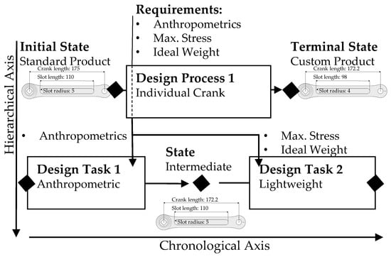
Figure 8.
Illustration of a MC process model for an individual bike crank, changing from a standard crank to a custom crank through two Design Tasks.
4.3. Annotations and Instantiation
To transfer the human processable model illustrated in Figure 8 into machine processable knowledge representation, the defined concepts are annotated to the virtual product in the product developers’ working environment. In the case of an individual bike crank, MC takes place in the mechanical domain and, therefore, a CAD environment is used. The annotation process is generally applicable, but software-dependent features have to be customized, as the software’s API is used to define new additional classes for objects in the kernel to store information. For this use case, Siemens NX1899 is used to visualize the annotation process. Accordingly, NXOpen is used as an API to manage annotations as UserAttributes for NXObjects. UserAttributes store custom data and are available for the majority of NXObjects (e.g., parts, bodies, expressions, etc.). They are particular easy to handle, as semantic annotations can be related to structural elements using the NXOpen.AttributePropertiesBuilder and can be queried by NXObject.GetUserAttributes. All annotations can be achieved manually, but to ease user interactions, the annotation process is guided by a custom built-in NXOpen application which is a GUI supporting the user to manage the processes.
Following the annotation process illustrated in Figure 5, the annotation of UserAttributes to the part in the CAD environment starts with the addition of a new MC process to the part which, in this case, is the bike crank. For Step 1, the requirements are manually instantiated or imported from an Excel sheet by adding new UserAttributes to the highest ranked object in the product’s model tree (e.g., part). Optional for NX, UserAttributes have categories which can help to classify annotations later on. As there has to be at least one Transition in the MC process, a Transition is added to the UserAttributes of the part. All instantiated requirements are related to this Transition as the Input Rationale, as this is the only Transition on the top level. This leads to step 2, where the user has to select either Design Task or Design Process for every new Transition. For the abovementioned reasons, the top level Transition has to be a Design Process. By specifying the Transition as a Design Process, all Input Rationales related to this Transition are queried. The user has to specify an Output Rationale for each related requirement. For the top level Design Process of the use case, all requirements are queried and split into anthropometric and lightweight, which are defined as Output Rationales 1 and 2. The resulting UserAttributes define the Design Process of the top level in the model of the use case and are related to the highest ranked object in the model tree, which is demonstrated in Figure 9.
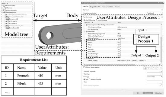
Figure 9.
Illustration of the annotation of a new MC Design process including the Requirements, the Design Process of the top level, and the corresponding Input and Output Design Rationales of virtual products in the CAD environment.
For each unique Output Rationale of the top Level Transition (Output Rationale 1 and Output Rationale 2 in case of the individualization of the bike crank), a new Transition is created in the next subordinate level. The order is taken into account for the sequence of the Transitions. In this particular case, two Transitions are instantiated (Step 3 in Figure 5). For the first Transition, the Beginning State is inherited. According to the model presented in Figure 8, this is the Design Task for the antroprometric adaption (see Appendix A). The corresponding source file is selected from the catalog and the Input Rationale (length of femur, fibula, and foot as floats in mm, angles for the hip, knee, and foot) and linked with the inputs of the solution principle. As the Input Rationale matches the input, the user is requested to select a Design Parameter for each output of the solution principle. For anthropometric adaption, one Design Parameter (Crank Length) has to be related to the corresponding structural element, which can be found in the expressions of the CAD model (Intermediate State in Figure 10). To complete the Design Process, all requirements have to be related to Design Parameters. Therefore, the second Transition for Design Task 2 is processed analogously to Design Task 1, and the Design Process reaches the Objective State, which is illustrated in the expression tab of the CAD model (Figure 10). All expressions at one point of the chronological axis form a State. To distinguish single states, annotations are filtered by Design Tasks.
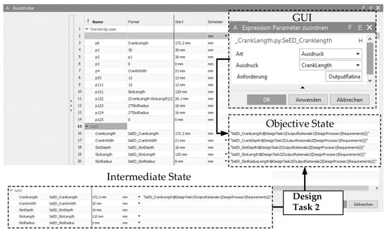
Figure 10.
Illustration of the GUI used to annotate the Rationale of Expressions and the Intermediate State and the Objective State in the Expression tab of the CAD model to demonstrate how States can be distinguished by utilizing Design Tasks as filters.
As the annotation process is completed, the user has to confirm the MC Process. The semantically enriched CAD model is instantiated as assertional knowledge in the SeEDMC. First, the wrapper loops the model tree and stores structural and semantic data in tables that are used to load the data into the SeEDMC. The semantic data and the relevant structural data are provided in Table A1, Table A2, Table A3, Table A4, Table A5, Table A6 and Table A7 of Appendix C. As an example, the code for the extrusion feature which is used as the annotation anchor in Figure 10 is provided in Appendix A.3. Second, the Protégé-Plugin Cellfie (https://github.com/protegeproject/cellfie-plugin, accessed on 24 September 2021) is used to write transformation rules in Manchester Syntax (see Transformation Rule in Figure 11) to transfer table data to individuals. With those rules, objects from a tables can be instantiated and linked via the ontology.The example in Figure 11 illustrates the instantiation of a Design Task. Through the inference rules of the ontology, individual Design Task 1 is related to the individual FitCrank, which is a Solution Principle and contains input and output information of the underlying python script (see Property assertions in Figure 11). Additionally, the respective Design Parameter SeED_CrankLength is related to Design Task 1. The individual contains the metrics of the terminal state of the design parameter, which are related via the data properties hasValue and hasUnit. A summary of the used transformation rules is provided in Appendix B.
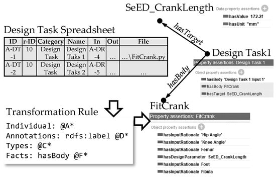
Figure 11.
Illustration of an example of the instantiation of a Design Task from data tables.
4.4. Knowledge Representation
Figure 12 shows an excerpt from the ontological knowledge representation visualized as a graph. Every annotation is of the Design Process or Design Task type, since a design process consists of different design tasks executed here by solution principles represented in a python script. For instance, the individual Anthropometric measures represent an annotation of the Design Task type, which links the individual FitCrankLength with an individual CrankLength of the Terminal State type. As described above, the input of the python script is input rationale derived from the requirements, in this case the individual’s Femur and Fibula lengths, which are anthropometric data. In this case, an individualized crank length results; thus, the individual CrankLength is of the Terminal State as well as Design Parameter types, since it is the only design parameter transformed in this state. The situation is different to the individual Slot, which is an extrusion feature in CAD and, thus, is composed of a 2D sketch and material removal of a certain depth. Therefore, for instance, the individual’s SlotLength, SlotDepth, SlotRadius, and CrankDepth of the Design Parameter type are transformed by the python script to fit the slot extrusion. In this way, information about the transition from one state to another is represented as linked data.
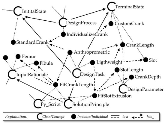
Figure 12.
Excerpt from the visualization of the ontological knowledge representation.
The resulting exemplary knowledge representation shown in Figure 12 enables the automation of the entire MC process from a standard crank (Initial State) to an custom bicycle crank (Terminal State). By utilizing Design Rationale (Input and Output Rationale for Transition), the relational conditions of Design Processes, and the solution principles of Design Tasks (FitCrankLength and FitSlotParameter), new individual values for requirements (e.g., Femur, Fibula, …) are linked with Design Parameters (e.g.,: CrankLength). Thus, every modification is traceable in the hierarchical axis of the MC process, and the design intent is explicable. In addition to this, relating the Design Parameters to Design Rationale makes the sequence of the modifications applicable for design automation, as the modifications can be filtered by the related Design Tasks, which are executed by the underlying scripts. As an example, removing all relations associated with the second Design Task (Lightweight), results in the Intermediate State presented in Figure 8. Therefore, the prescribed order of States forms the chronological axis of the MC process. The advantage and difference to previous approaches is that not only are the individual Design Tasks automated but their context is used to ensure their seamless linkage.
5. Discussion
This contribution demonstrates how knowledge representation can be designed and annotated to a virtual product in order to enable design automation for entire mass customization processes. One can see that the knowledge representation shown in Figure 12 relates states, which are expressed as design parameters (e.g., SlotLength), to design tasks (e.g., LightWeight) and design processes (e.g., IndividualizeCrank). Therefore, product and process knowledge are linked via the ontology. The Transition concept of the SeEDMC ontology can be easily extended by more sophisticated representations of the design intent. As other publications [22,53,63,64] have focused on the design intent as product knowledge, here, the focus was more on the integration of the design process. In order to be able to describe and subsequently model MC processes, the limitations and possibilities were derived from the categorization of product development processes according to the degree of innovation [29]. From this categorization, it was concluded that the adaptation design offers greater scope for innovation than repeat or variant design, although the principle solution (solution principles and modular structure) may not be changed here either. Consequently, innovative new designs are not included in the scope of the model described. In rare cases, however, adaptation designs at the product level include new designs of individual components. These cannot yet be represented by the model and must be considered separately. The limitation on adaptation designs leads to a variety of constraints for design tasks. First, for mass customization as well as adapation design, a prior design process that offers solution principles and modular structure is required. The current state of SeEDMC relies on these, as they guide the modeling process and assure that the constraints are evident to the user and can be modeled correctly. In addition to this, solution principles must be in a processable form that explicitly states inputs for design rationale and outputs for design parameters. As illustrated in [65], there are a variety of design intents that are still not included at this point. Analogously, further restrictions result from the prescribed structures for the concepts Design Task and Design Process. These elementary concepts of knowledge representation are not inferred but are predefined and thus cannot be adapted at will. Furthermore, manual errors in the annotation process are not yet checked for plausibility. Thus, product developers can select arbitrary design parameters and link them to the outputs of the solution principles without considering their purposes. This is emphasized here once more, as the current process of modelling depends heavily on the decisions of the user. For example, an angle can be annotated for the lever arm of an solution principle for torque transmission, which actually has to be a length. Therefore, the constraints have to be quite polyvalent.
However, the checks for this could be implemented as a future extension, in which the concept for the design parameters is further detailed by concepts for structural elements. A possible classification for this was presented by Brunetti and Grimm [66]. Compared with other approaches to ontological knowledge representation for design automation, SeEDMC is notable for its simultaneous consideration of different types of design rationale, their relationships with design parameters, and their chronological sequence as design processes. This enables modeling and, thus, enhances the traceability of the design intent for design tasks. This relationship is referred to as the hierarchical axis in the model. The temporal sequence allows these design tasks to be linked to processes and is referenced as a chronological axis. Thus, SeEDMC is the only knowledge representation for design automation that can process and provide the product development process itself as knowledge for reuse. This is particularly important when constraints for subsequent design tasks result from a previous design task, for example, if the design space is limited by a previous design task and this is not taken into account in the subsequent adaptations. If constraints are not interpreted at all or are interpreted incorrectly, this can result in the design tasks having to be repeated. Additional iterations in the MC process and thus a higher development effort are the consequences. Those constraints are included in the presented approach through transitions between the states; thus, the steps throughout an adaptation are automatically taken into account in subsequent design tasks. This makes the whole MC process transparent and traceable.
6. Summary and Conclusions
In order to define the prerequisites that knowledge representation must satisfy to enable design automation for mass customization, this contribution has presented a model for the mass customization process, concepts, and axioms of the SeEDMC ontology, which state the intentional knowledge of the model, an annotation scheme, and the process used to integrate the knowledge representation into the working environment of product developers. Finally, a mapping scheme is given to instantiate assertional knowledge about individual mass customization processes. The main purpose of the SeEDMC is to represent the design process and to enable seamless design automation by reusing this knowledge. More sophisticated representation for design intent can be found in [21,22,65,67]. This is achieved by modeling the mass customization process in two dimensions, the hierarchical and the chronological axes. The former represents relationships between the design intent, as design rationale, from the requirements to the design parameters. The latter represents the temporal sequence of adaptations with the help of states and transitions. Together they form the concepts and axioms as intentional knowledge of the SeEDMC. In order to meet requirements one to three for knowledge representations outlined in the introduction, the SeEDMC is characterized by an ontology that can be processed by humans and machines with a minimal number of concepts that are oriented towards the engineer’s vocabulary and can thus be easily aligned to other knowledge representations. Integration into the environment by product developers is realized by the annotation scheme and process. Design Parameters are used as targets, while other concepts of SeEDMC are stated in the annotations’ bodies. As this meets requirement four, the fifth and last requirement is achieved by automatically transferring the design parameters and the annotations into the SeEDMC using a mapping scheme and design wrapper [14]. The feasibility has been probed through the implementation of a mass customization process for an individual bike crank. To validiate the method, future work should include user studies in an industrial environment.
By providing a representation of the design process under the constraints of mass customization, the SeEDMC supplies an unconsidered, elementary component for knowledge representations for design automation. Future work should include checking for the plausibility of targets and bodies of the annotation scheme to prevent manual errors. An exact annotation is particularly relevant when selecting the Design Parameters of the Solutions Principles, as otherwise, incorrect characteristics of the product will be adapted. Therefore, a knowledge representation for the domain of structural elements could be aligned to the SeEDMC. As a consequence, it can be checked whether the output of the solution principle and the design parameter selected for it are of the same type or have the same unit. Subsequently, the annotation process, which is currently performed manually, could be (partially) automated by inferring Design Parameters for Solution Principles. However, this further automation requires very detailed knowledge representation for the domain of structural elements.
Author Contributions
Conceptualization, F.D., B.S. and S.W.; methodology, F.D. and B.S.; software, F.D. and P.K.; investigation, F.D. and P.K.; writing—original draft preparation, F.D. and P.K.; writing—review and editing, B.S. and S.W.; visualization, F.D. and P.K.; supervision, B.S. and S.W.; project administration, S.W.; funding acquisition, S.W. All authors have read and agreed to the published version of the manuscript.
Funding
This work was supported by the European Regional Development Fund within the “Optimization-based design methodology in the early phase of the mechatronic product development” (ERDF/OptMePro) project & by the German Research Foundation (DFG) [WA 2913/22-2] within the Priority Program 1921.
Conflicts of Interest
The authors declare that they have no known competing financial interests or personal relationships that could have appeared to influence the work reported in this paper.
Abbreviations
The following abbreviations are used in this manuscript:
| SeEDMC | Semantic integration for Engineering Design in Mass Customization |
| MC | Mass Customization |
| DA | Design Automation |
| KBE | Knowledge-based Engineering |
| KB | Knowledge Base |
Appendix A. Solution Principles for Individual Bike Crank
Appendix A.1. Anthropometric
- import sys
- import numpy as np
- class FitCrankLength(SolutionPrinciple):
- def __init__(self, Femur, Fibula, Foot, SeatTubeAngle, MinKneeAngle, MinFootAngle):
- # Inputs
- self.SeED_Femur = Femur # Distance Hip -> Knee in mm
- self.SeED_Fibula = Fibula # Distance Knee -> Ankle in mm
- self.SeED_Foot = Foot # Distance Ankle -> Toe in mm
- self.SeED_SeatTubeAngle = SeatTubeAngle # Seat tube Angle in Degrees
- self.SeED_MinKneeAngle = MinKneeAngle # Minimal Knee Angle in Degrees
- self.SeED_MinFootAngle = MinFootAngle # Minimal Foot Angle in Degrees}
- self.Input = locals()
- # Outputs
- self.SeED_CrankLength = 175.00 # Individual Crank Length in mm
- self.Output = locals() - self.Input
- pass
- def calculate(self):
- help_1 = self.SeED_Fibula**2 + self.SeED_Fibula**2 - (2*self.SeED_Fibula*SeED_Fibula*np.cos(self.SeED_MinFootAngle))
- help_2 = 180 - self.SeED_MinKneeAngle - np.arcsin((self.SeED_Foot*sin(self.SeED_MinFootAngle))/help_1)
- self.SeED_CrankLength = np.sin(help_2) * self.SeED_Femur - ((help_1 + np.cos(help_2) * self.SeED_Femur) / np.tan(self.SeED_SeatTubeAngle))
- return
- def getParameter():
- print(FitCrankLength.__dict__.keys())
- if len(sys.argv)>1 and sys.argv[1]=="getParameter":
- FitCrankLength.getParameter()
Appendix A.2. Lightweight
- import sys
- import pickle
- import numpy as np
- class AdaptSlotParameters(SolutionPrinciple):
- def __init__(self, IdealMass, MaxStress):
- # Inputs
- self.SeED_IdealMass = IdealMass # Ideal Mass of the Crank in kg
- self.SeED_MaxStress = MaxStress # Max. Stress According to asigned Material in N/mm**2
- self.Input = locals()
- # Outputs
- self.SeED_CrankDepth = 20.00 # Individual Crank Depth in mm
- self.SeED_SlotLength = 100.00 # Individual Slot Length in mm
- self.SeED_SlotDepth = 15.00 # Individual Slot Depth in mm
- self.SeED_SlotRadius = 7.00 # Individual Slot Radius in mm
- self.Output = locals() - self.Input
- pass
- def calculate(self):
- X = np.atleast_2d([self.SeED_IdealMass, self.SeED_MaxStress]).T
- model = pickle.load(open(r"FEM_DIN_EN_ISO_4210-8.pkl", ’rb’))
- self.SeED_CrankDepth, self.SeED_SlotLength, self.SeED_SlotDepth, self.SeED_SlotRadius = model.predict(X)[0]
- return
- def getParameter():
- print(AdaptSlotParameters.__dict__.keys())
- if len(sys.argv)>1 and sys.argv[1]=="getParameter":
- AdaptSlotParameters.getParameter()
Appendix A.3. SeED for the Extrude Feature
- Function featureExtrude(bodyID As Integer, extrude As Features.Feature) As Integer
- id = javaVerbindung.getMaxID("FEATURE", "FEATUREID") + 1
- name = extrude.JournalIdentifier ’GetFeatureName
- Dim start As Double = extrude.GetExpressions(0).Value
- Dim ende As Double = 0
- If extrude.GetExpressions.Length > 1 Then
- ende = extrude.GetExpressions(1).Value
- End If
- reftype = ""
- refid = 0
- If extrude.GetParents(0).GetType.ToString.Equals("NXOpen.Features.SketchFeature") Then
- refid = featureSkizze(extrude.GetParents(0))
- reftype = "SKETCH"
- ElseIf extrude.GetParents(0).GetType.ToString.Equals("NXOpen.Features.Extrude") Then
- For Each d As DBFeature In dbFeatureList
- If d.getName.Equals(extrude.GetParents(0).JournalIdentifier()) Then
- refid = d.getID
- End If
- Next d
- reftype = "FEATURE"
- Else
- Guide.InfoWriteLine(extrude.GetParents(0).GetType.ToString)
- refid = 0
- End If
- dbFeatureList.Add(New DBFeature(id, name))
- sqlQuery = "INSERT INTO Feature (FEATUREID, bodyID, type, name, REFERENCE1, REFERENCE1TYPE, PARAMETER1, PARAMETER2) VALUES (" & id & "," & bodyID & ", ’EXTRUDE’,’" & name & "’," & refid & ",’" & reftype & "’," & start.ToString(System.Globalization.CultureInfo.InvariantCulture) & "," & ende.ToString(System.Globalization.CultureInfo.InvariantCulture) & ") ; "
- javaVerbindung.executeQuery(sqlQuery)
- ’%%%%%%%%%%%%%% S Q L %%%%%%%%%%%%%%’
- annotationList.Add(New AnnotationListItem(extrude.GetUserAttributes, id, "FEATURE", extrude))
- Return id
- End Function
Appendix B. Transformation Rules for the Individual Bike Crank
- {"Collections":[{"sheetName":"Expressions","startColumn":"A","endColumn":"A","startRow":"2","endRow":"+","comment":"","rule":"Individual: @B*\nTypes: TerminalState\nAnnotations: rdfs:comment @H*","active":true},{"sheetName":"Expressions","startColumn":"A","endColumn":"A","startRow":"2","endRow":"+","comment":"","rule":"Individual: @A*\nAnnotations: rdfs:label @D*\nTypes: DesignParameter\nFacts: hasValue @F*(xsd:float), hasUnit @G*(xsd:string), isDesignParameterOf @B*","active":true},{"sheetName":"DesignProcess","startColumn":"A","endColumn":"A","startRow":"2","endRow":"+","comment":"","rule":"Individual: @A*\nTypes: @C*\nAnnotations: rdfs:label @D*\nFacts: hasBody @F*, hasBody @G*, hasTarget @B*","active":true},{"sheetName":"Features","startColumn":"A","endColumn":"A","startRow":"2","endRow":"+","comment":"","rule":"Individual: @A*\nTypes: ObjectiveState\nAnnotations: rdfs:label \"CustomCrank_10\"","active":true},{"sheetName":"Requirements","startColumn":"A","endColumn":"A","startRow":"2","endRow":"+","comment":"","rule":"Individual: @A*\nAnnotations: rdfs:label @D*\nTypes: @C*\nFacts: hasValue @F*(xsd:float), hasUnit @G*(xsd:string), isRequirementOf @B*","active":true},{"sheetName":"DesignRationales","startColumn":"A","endColumn":"A","startRow":"2","endRow":"+","comment":"","rule":"Individual: @A*\nTypes: @C*\nAnnotations: rdfs:label @D*\nFacts: hasRequirement @F*","active":true},{"sheetName":"DesignTask","startColumn":"A","endColumn":"A","startRow":"2","endRow":"+","comment":"","rule":"Individual: @A*\nAnnotations: rdfs:label @D*\nTypes: @C*\nFacts: hasBody @F*","active":true}]}
Appendix C. Excerpt of Relevant Structural and Semantic Data from the Use Case
Table A1.
Annotated Requirements for the bike crank use case.
Table A1.
Annotated Requirements for the bike crank use case.
| ID | r-ID | Category | Name | Value | Unit |
|---|---|---|---|---|---|
| A-R1 | 10 | Requirement | Femur | 410 | mm |
| A-R2 | 10 | Requirement | Fibula | 435 | mm |
| A-R3 | 10 | Requirement | Foot | 211 | mm |
| A-R4 | 10 | Requirement | min. Knee Angle | 105 | ° |
| A-R5 | 10 | Requirement | min. Foot Angle | 110 | ° |
| A-R6 | 10 | Requirement | idl. Mass | 0.180 | kg |
| A-R7 | 10 | Requirement | max. Stress | 210 | N/mm−2 |
Table A2.
Annotated Transitions for the bike crank use case.
Table A2.
Annotated Transitions for the bike crank use case.
| ID | r-ID | Category | Name | Value |
|---|---|---|---|---|
| A-T1 | 10 | Transition | Transition 1 | A-DP-1 |
| A-T2 | 10 | Transition | Transition 2 | A-DT-1 |
| A-T3 | 10 | Transition | Transition 3 | A-DT-2 |
Table A3.
Annotated Design Process for the bike crank use case.
Table A3.
Annotated Design Process for the bike crank use case.
| ID | r-ID | Category | Name | In | Out |
|---|---|---|---|---|---|
| A-DP-1 | 10 | Design Process | Design Process 1 | A-ADR-1 | A-DR-2 |
| A-DP-1 | 10 | Design Process | Design Process 1 | A-ADR-1 | A-DR-3 |
Table A4.
Annotated Design Tasks for the bike crank use case.
Table A4.
Annotated Design Tasks for the bike crank use case.
| ID | r-ID | Category | Name | in | Out | File |
|---|---|---|---|---|---|---|
| A-DT-1 | 10 | Design Task | Design Taks 1 | A-ADR-4 | [CrankLength] | FitCrank.py |
| A-DT-2 | 10 | Design Task | Design Taks 2 | A-ADR-5 | [CrankWidth, | Adapt |
| SlotLength, | Slot | |||||
| SlotWidth, | Parameters | |||||
| SlotRadius] | .py |
Table A5.
Annotated Design Rationale for the bike crank use case.
Table A5.
Annotated Design Rationale for the bike crank use case.
| ID | r-ID | Category | Name | Value |
|---|---|---|---|---|
| A-DR-1 | 10 | Design Rationale | Design Process 1 Input 1 | [A-R1, …, A-R7] |
| A-DR-2 | 10 | Design Rationale | Design Process 1 Output 1 | [A-R1, …, A-R5] |
| A-DR-3 | 10 | Design Rationale | Design Process 1 Output 2 | [A-R6, A-R7] |
| A-DR-4 | 10 | Design Rationale | Design Task 1 Input 1 | [A-R1, …, A-R5] |
| A-DR-5 | 10 | Design Rationale | Design Task 2 Input 1 | [A-R6, A-R7] |
Table A6.
Extrusion Feature used as target for the Annotations of Appendix C Table A1, Table A2, Table A3, Table A4 and Table A5.
| ID | r-ID | x-pos. | y-pos. | z-pos. | type | length | sketch | Annotation |
|---|---|---|---|---|---|---|---|---|
| 10 | 1 | 0 | 0 | 0 | 5 | 21.0 | 10-1 | [UserAttributes **] |
Table A7.
Expressions of the bike crank use case in the Terminal State.
Table A7.
Expressions of the bike crank use case in the Terminal State.
| ID | r-ID | Category | Name | Value | Unit | Comment |
|---|---|---|---|---|---|---|
| CrankLength | Sketch 10-1 | Expression | SeED_ CrankLength | 172.2 | mm | SeED_CrankLength@ DesignTask1(OutputRationale1( DesignProcess1(Requirements))) |
| CrankWidth | Sketch 10-1 | Expression | SeED_ CrankWidth | 21 | mm | SeED_CrankDepth@ DesignTask2(OutputRationale2( DesignProcess1(Requirements))) |
| SlotDepth | Sketch 20-1 | Expression | SeED_ SlotDepth | 16 | mm | SeED_SlotDepth@ DesignTask2(OutputRationale2( DesignProcess1(Requirements))) |
| SlotLength | Sketch 20-1 | Expression | SeED_ SlotLength | 120 | mm | SeED_SlotLength@ DesignTask2(OutputRationale2( DesignProcess1(Requirements))) |
| SlotRadius | Sketch 20-1 | Expression | SeED_ SlotRadius | 8 | mm | SeED_SlotRadius@ DesignTask2(OutputRationale2( DesignProcess1(Requirements))) |
| p0 | Extrusion 10 | Expression | CrankLength | 172.2 | mm | |
| p1 | Extrusion 10 | Expression | SeED_ CrankWidth | 21 | mm | |
| p2 | Extrusion 10 | Expression | p1 | 21 | mm | |
| p3 | Extrusion 10 | Expression | 0 | 0 | mm | |
| p4 | Extrusion 10 | Expression | CrankWidth | 21 | mm | |
| p53 | Hole-1 | Expression | 12 | 12 | mm | |
| p111 | Hole-2 | Expression | 12 | 12 | mm | |
| p121 | Extrusion 20 | Expression | SlotLength | 120 | mm | |
| p122 | Extrusion 20 | Expression | (CrankLength- SlotLength)/2 | 26.1 | mm | |
| p123 | Extrusion 20 | Expression | 2*SlotRadius | 16 | mm | |
| p124 | Extrusion 20 | Expression | 2*SlotRadius | 16 | mm | |
| p125 | Extrusion 20 | Expression | 0 | 0 | mm |
References
- Liu, S.; Boyle, I.M. Engineering design: Perspectives, challenges, and recent advances. J. Eng. Des. 2009, 20, 7–19. [Google Scholar] [CrossRef]
- Fogliatto, F.S.; Da Silveira, G.J.; Borenstein, D. The mass customization decade: An updated review of the literature. Int. J. Prod. Econ. 2012, 138, 14–25. [Google Scholar] [CrossRef]
- Ramani, K.; Cunningham, R.; Devanathan, S.; Subramaniam, J.; Patwardhan, H. Technology Review of Mass Customization. 2004, pp. 5–11. Available online: http://citeseerx.ist.psu.edu/viewdoc/download?doi=10.1.1.448.1905&rep=rep1&type=pdf (accessed on 19 October 2021).
- Verhagen, W.J.; Bermell-Garcia, P.; Van Dijk, R.E.; Curran, R. A critical review of Knowledge-Based Engineering: An identification of research challenges. Adv. Eng. Inform. 2012, 26, 5–15. [Google Scholar] [CrossRef]
- Bracewell, R.; Wallace, K.; Moss, M.; Knott, D. Capturing design rationale. Comput.-Aided Des. 2009, 41, 173–186. [Google Scholar] [CrossRef]
- Górski, F.; Zawadzki, P.; Hamrol, A. Knowledge based engineering as a condition of effective mass production of configurable products by design automation. J. Mach. Eng. 2016, 16, 5–30. [Google Scholar]
- Camba, J.D.; Contero, M.; Hartman, N. The Cost of Change in Parametric Modeling: A Roadmap. Comput.-Aided Des. Appl. 2021, 18, 634–643. [Google Scholar] [CrossRef]
- Russell, S.; Norvig, P. Artificial Intelligence: A Modern Approach, Global, 4th ed.; Pearson: Deutschland, Germany, 2021. [Google Scholar]
- Davis, R.; Shrobe, H.; Szolovits, P. What is a knowledge representation? AI Mag. 1993, 14, 17–33. [Google Scholar]
- Studer, R.; Benjamins, V.R.; Fensel, D. Knowledge Engineering: Principles and methods. Data Knowl. Eng. 1998, 25, 161–197. [Google Scholar] [CrossRef]
- Gruber, T.R. Toward principles for the design of ontologies used for knowledge sharing. Int. J. Hum. Comput. Stud. 1995, 43, 907–928. [Google Scholar] [CrossRef]
- Hoekstra, R. The knowledge reengineering bottleneck. Semant. Web 2010, 1, 111–115. [Google Scholar] [CrossRef]
- Feigenbaum, E.A. Knowledge Engineering: The Applied Side of Artificial Intelligence. Ann. N. Y. Acad. Sci. 1984, 426, 91–107. [Google Scholar] [CrossRef]
- Dworschak, F.; Kügler, P.; Schleich, B.; Wartzack, S. Integrating The Mechanical Domain Into Seed Approach. In Proceedings of the Design Society: International Conference on Engineering Design, Delft, The Netherlands, 5–8 August 2019; Cambridge University Press: Cambridge, UK, 2019; Volume 1, pp. 2587–2596. [Google Scholar] [CrossRef]
- Owen, R.; Horváth, I. Towards product-related knowledge asset warehousing in enterprises. In Proceedings of the 4th International Symposium on Tools and Methods of Competitive Engineering (TMCE), Wuhan, China, 22–26 April 2002; Volume 2002, pp. 155–170. [Google Scholar]
- Roller, D. An approach to computer-aided parametric design. Comput.-Aided Des. 1991, 23, 385–391. [Google Scholar] [CrossRef]
- Anderl, R.; Mendgen, R. Modelling with constraints: Theoretical foundation and application. Comput.-Aided Des. 1996, 28, 155–168. [Google Scholar] [CrossRef]
- Gerritsen, B. Special Issue Current State and Future of Product Data Technologies (PDT); Elsevier: Amsterdam, The Netherlands, 2008. [Google Scholar]
- Chandrasegaran, S.K.; Ramani, K.; Sriram, R.D.; Horváth, I.; Bernard, A.; Harik, R.F.; Gao, W. The evolution, challenges, and future of knowledge representation in product design systems. Comput.-Aided Des. 2013, 45, 204–228. [Google Scholar] [CrossRef]
- Tomiyama, T. Intelligent computer-aided design systems: Past 20 years and future 20 years. AI EDAM 2007, 21, 27–29. [Google Scholar] [CrossRef][Green Version]
- Camba, J.D.; Contero, M.; Company, P. Parametric CAD modeling: An analysis of strategies for design reusability. Comput.-Aided Des. 2016, 74, 18–31. [Google Scholar] [CrossRef]
- Camba, J.D.; Contero, M. Assessing the impact of geometric design intent annotations on parametric model alteration activities. Comput. Ind. 2015, 71, 35–45. [Google Scholar] [CrossRef]
- Görz, G.; Schneeberger, J.; Schmid, U. (Eds.) Handbuch der künstlichen Intelligenz, 5th ed.; Oldenbourg: München, Germany, 2014. [Google Scholar]
- Levesque, H.J. Knowledge Representation and Reasoning. Annu. Rev. Comput. Sci. 1986, 1, 255–287. [Google Scholar] [CrossRef]
- Gruber, T.R. A translation approach to portable ontology specifications. Knowl. Acquis. 1993, 5, 199–221. [Google Scholar] [CrossRef]
- Guarino, N.; Oberle, D.; Staab, S. What is an ontology? In Handbook on Ontologies; Springer: Berlin/Heidelberg, Germany, 2009; pp. 1–17. [Google Scholar]
- Chapman, C.; Pinfold, M. The application of a knowledge based engineering approach to the rapid design and analysis of an automotive structure. Adv. Eng. Softw. 2001, 32, 903–912. [Google Scholar] [CrossRef]
- Frank, G.; Entner, D.; Prante, T.; Khachatouri, V.; Schwarz, M. Towards a generic framework of engineering design automation for creating complex CAD models. Int. J. Adv. Syst. Meas. 2014, 7, 179–192. [Google Scholar]
- Ehrlenspiel, K.; Meerkamm, H. Integrierte Produktentwicklung: Denkabläufe, Methodeneinsatz, Zusammenarbeit; Carl Hanser Verlag GmbH Co. KG: Munich, Germany, 2017. [Google Scholar]
- Szykman, S.; Sriram, R.D.; Regli, W.C. The Role of Knowledge in Next-generation Product Development Systems. J. Comput. Inf. Sci. Eng. 2000, 1, 3–11. [Google Scholar] [CrossRef]
- Regli, W.C.; Hu, X.; Atwood, M.; Sun, W. A survey of design rationale systems: Approaches, representation, capture and retrieval. Eng. Comput. 2000, 16, 209–235. [Google Scholar] [CrossRef]
- Sanfilippo, E.M.; Borgo, S. What are features? An ontology-based review of the literature. Comput.-Aided Des. 2016, 80, 9–18. [Google Scholar] [CrossRef]
- Erden, M.S.; Komoto, H.; van Beek, T.J.; D’Amelio, V.; Echavarria, E.; Tomiyama, T. A review of function modeling: Approaches and applications. Ai Edam 2008, 22, 147–169. [Google Scholar] [CrossRef]
- Garbacz, P.; Borgo, S.; Carrara, M.; Vermaas, P.E. Two ontology-driven formalisations of functions and their comparison. J. Eng. Des. 2011, 22, 733–764. [Google Scholar] [CrossRef]
- Stone, R.B.; Wood, K.L. Development of a functional basis for design. J. Mech. Des. 2000, 122, 359–370. [Google Scholar] [CrossRef]
- Chandrasekaran, B. Functional representation and causal processes. Adv. Comput. 1994, 38, 73–143. [Google Scholar]
- Goel, A.; Rugaber, S.; Vattam, S. Structure, behavior & function of complex systems: The SBF modeling language. Int. J. Eng. Des. Anal. Manuf. 2009, 23, 23–35. [Google Scholar]
- Goel, A.; Bhatta, S.; Stroulia, E. Kritik: An early case-based design system. Issues Appl. -Case-Based Reason. Des. 1997, 1997, 87–132. [Google Scholar]
- Bhatta, S.; Goel, A.; Prabhakar, S. Innovation in analogical design: A model-based approach. In Artificial Intelligence in Design 94; Springer: Berlin/Heidelberg, Germany, 1994; pp. 57–74. [Google Scholar]
- Yaner, P.W.; Goel, A.K. Analogical recognition of shape and structure in design drawings. Artif. Intell. Eng. Des. Anal. Manuf. AI EDAM 2008, 22, 117–120. [Google Scholar] [CrossRef]
- Goel, A.K.; Vattam, S.; Wiltgen, B.; Helms, M. Cognitive, collaborative, conceptual and creative—Four characteristics of the next generation of knowledge-based CAD systems: A study in biologically inspired design. Comput.-Aided Des. 2012, 44, 879–900. [Google Scholar] [CrossRef]
- Pratt, M.J. Introduction to ISO 10303—The STEP standard for product data exchange. J. Comput. Inf. Sci. Eng. 2001, 1, 102–103. [Google Scholar] [CrossRef]
- Patil, L.; Dutta, D.; Sriram, R. Ontology-Based Exchange of Product Data Semantics. Autom. Sci. Eng. IEEE Trans. 2005, 2, 213–225. [Google Scholar] [CrossRef]
- Fiorentini, X.; Gambino, I.; Liang, V.C.; Rachuri, S.; Mani, M.; Nistir, C.B.; Bock, C.; Gutierrez, C.M.; Turner, J.M. An Ontology for Assembly Representation; National Institute of Standards and Technology: Gaithersburg, MD, USA, 2007.
- Fenves, S.; Foufou, S.; Bock, C.; Sriram, R. CPM: A core model for product data. J. Comput. Inf. Sci. Eng. JCISE 2008, 5. [Google Scholar] [CrossRef]
- Krima, S.; Barbau, R.; Fiorentini, X.; Sudarsan, R.; Sriram, R.D. Ontostep: OWL-DL ontology for step. Natl. Inst. Stand. Technol. NISTIR 2009, 7561. [Google Scholar]
- Barbau, R.; Krima, S.; Rachuri, S.; Narayanan, A.; Fiorentini, X.; Foufou, S.; Sriram, R.D. OntoSTEP: Enriching product model data using ontologies. Comput.-Aided Des. 2012, 44, 575–590. [Google Scholar] [CrossRef]
- Kohlhase, M. Knowledge management for systematic engineering design in CAD systems. Prof. Wissenmanagement Manag. Konf. 2013, 7, 202–217. [Google Scholar]
- Breitsprecher, T.; Codescu, M.; Jucovschi, C.; Kohlhase, M. Semantic Support for Engineering Design Processes. In Proceedings of the DESIGN 2014 13th International Design Conference, Dubrovnik, Croatia, 19–22 May 2013; pp. 1723–1732. [Google Scholar]
- Kohlhase, M. OMDoc—An Open Markup Format for Mathematical Documents [version 1.2]: Foreword by Alan Bundy; Springer: Berlin/Heidelberg, Germany, 2006; Volume 4180. [Google Scholar]
- Pahl, G.; Beitz, W. Engineering Design: A Systematic Approach; Springer Science & Business Media: Berlin/Heidelberg, Germany, 2013. [Google Scholar]
- Maschinenbau, V.F. Wissensbasierte 3D-CAD Repräsentation. 2003. Available online: http://www.shaker.de/Online-Gesamtkatalog-Download/2021.10.20-08.54.33-142.11.248.19-radAE56F.tmp/3-8322-2363-0_INH.PDF (accessed on 24 September 2021).
- Bodein, Y.; Rose, B.; Caillaud, E. A roadmap for parametric CAD efficiency in the automotive industry. Comput.-Aided Des. 2013, 45, 1198–1214. [Google Scholar] [CrossRef]
- Roth, K. Konstruieren mit Konstruktionskatalogen: Band 1: Konstruktionslehre; Springer: Berlin/Heidelberg, Germany, 2011; Volume 1. [Google Scholar]
- Sanderson, R.; Ciccarese, P.; Young, B. Web Annotation Data Model: W3C Recommendation. 2017. Available online: https://www.w3.org/TR/annotation-model/ (accessed on 24 September 2021).
- Klein, M. Combining and relating ontologies: An analysis of problems and solutions. In OIS@ IJCAI; 2001; Available online: https://citeseerx.ist.psu.edu/viewdoc/download?doi=10.1.1.13.3504&rep=rep1&type=pdf#page=55 (accessed on 24 September 2021).
- Litzenberger, S.; Illes, S.; Hren, M.; Reichel, M.; Sabo, A. Influence of Pedal Foot Position on Muscular Activity during Ergometer Cycling (P39). In The Engineering of Sport 7; Springer: Berlin/Heidelberg, Germany, 2008; pp. 215–222. [Google Scholar] [CrossRef]
- Paton, C.D. Effects of shoe cleat position on physiology and performance of competitive cyclists. Int. J. Sport. Physiol. Perform. 2009, 4, 517–523. [Google Scholar] [CrossRef]
- Ericson, M.O.; Nisell, R. Efficiency of pedal forces during ergometer cycling. Int. J. Sport. Med. 1988, 9, 118–122. [Google Scholar] [CrossRef] [PubMed]
- Ericson, M.O.; Nisell, R. Patellofemoral joint forces during ergometric cycling. Phys. Ther. 1987, 67, 1365–1369. [Google Scholar] [CrossRef] [PubMed]
- Bini, R.R.; Hume, P.A.; Croft, J.; Kilding, A. Optimizing bicycle configuration and cyclists’ body position to prevent overuse injury using biomechanical approaches. In Biomechanics of Cycling; Springer: Berlin/Heidelberg, Germany, 2014; pp. 71–83. [Google Scholar] [CrossRef]
- DIN EN ISO 4210-8:2015-01. Cycles—Safety Requirements for Bicycles—Part 8: Pedal and Drive System Test Methods (ISO 4210-8:2014), German Version EN ISO 4210-8:2014; Available online: https://www.clinicalbikefit.com/wp-content/uploads/2017/10/patellarfemoralstrain.pdf (accessed on 24 September 2021).
- Camba, J.; Contero, M.; Johnson, M.; Company, P. Extended 3D annotations as a new mechanism to explicitly communicate geometric design intent and increase CAD model reusability. Comput.-Aided Des. 2014, 57, 61–73. [Google Scholar] [CrossRef]
- Kyratzi, S.; Azariadis, P. A Constraint-based Framework to Recognize Design Intent during Sketching in Parametric Environments. Comput.-Aided Des. Appl. 2021, 18, 545–560. [Google Scholar] [CrossRef]
- Otey, J.; Company, P.; Contero, M.; Camba, J.D. Revisiting the design intent concept in the context of mechanical CAD education. Comput.-Aided Des. Appl. 2018, 15, 47–60. [Google Scholar] [CrossRef]
- Brunetti, G.; Grimm, S. Feature ontologies for the explicit representation of shape semantics. Int. J. Comput. Appl. Technol. 2005, 23, 192–202. [Google Scholar] [CrossRef]
- Bodein, Y.; Rose, B.; Caillaud, E. Explicit reference modeling methodology in parametric CAD system. Comput. Ind. 2014, 65, 136–147. [Google Scholar] [CrossRef]


Publisher’s Note: MDPI stays neutral with regard to jurisdictional claims in published maps and institutional affiliations. |
© 2021 by the authors. Licensee MDPI, Basel, Switzerland. This article is an open access article distributed under the terms and conditions of the Creative Commons Attribution (CC BY) license (https://creativecommons.org/licenses/by/4.0/).