
Dosimetric Optimization of a Laser-Driven Irradiation Facility Using the G4-ELIMED Application

 ,
,  and
and
Abstract
:1. Introduction
2. Materials and Methods
2.1. The G4-ELIMED Application
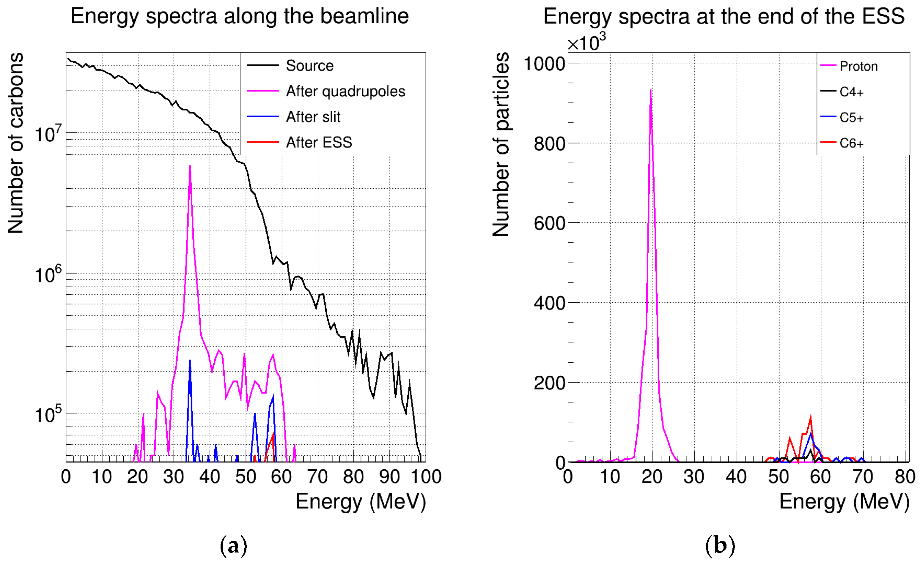
2.2. Source Implementation
2.3. Depth-Dose Profile Generation
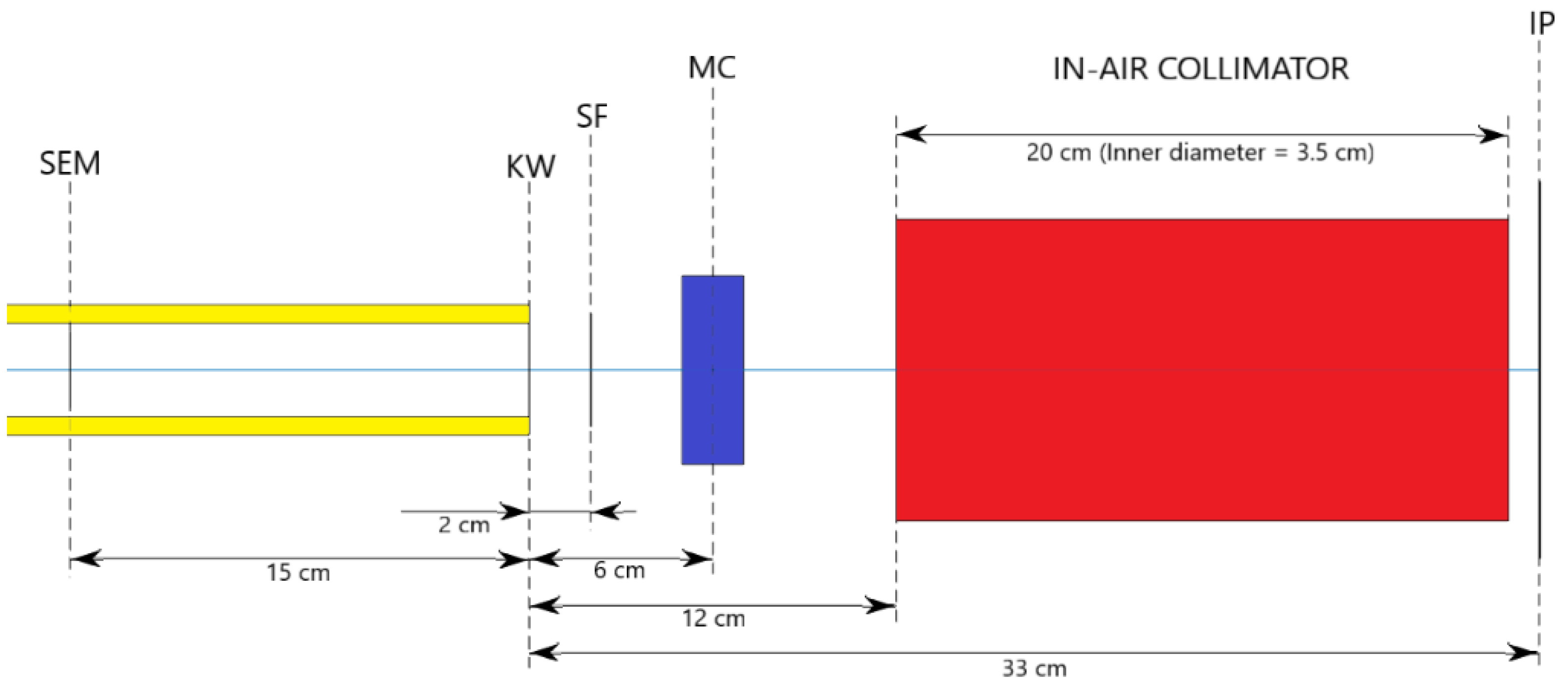
2.4. In-Air Configuration of the Beamline
3. Results
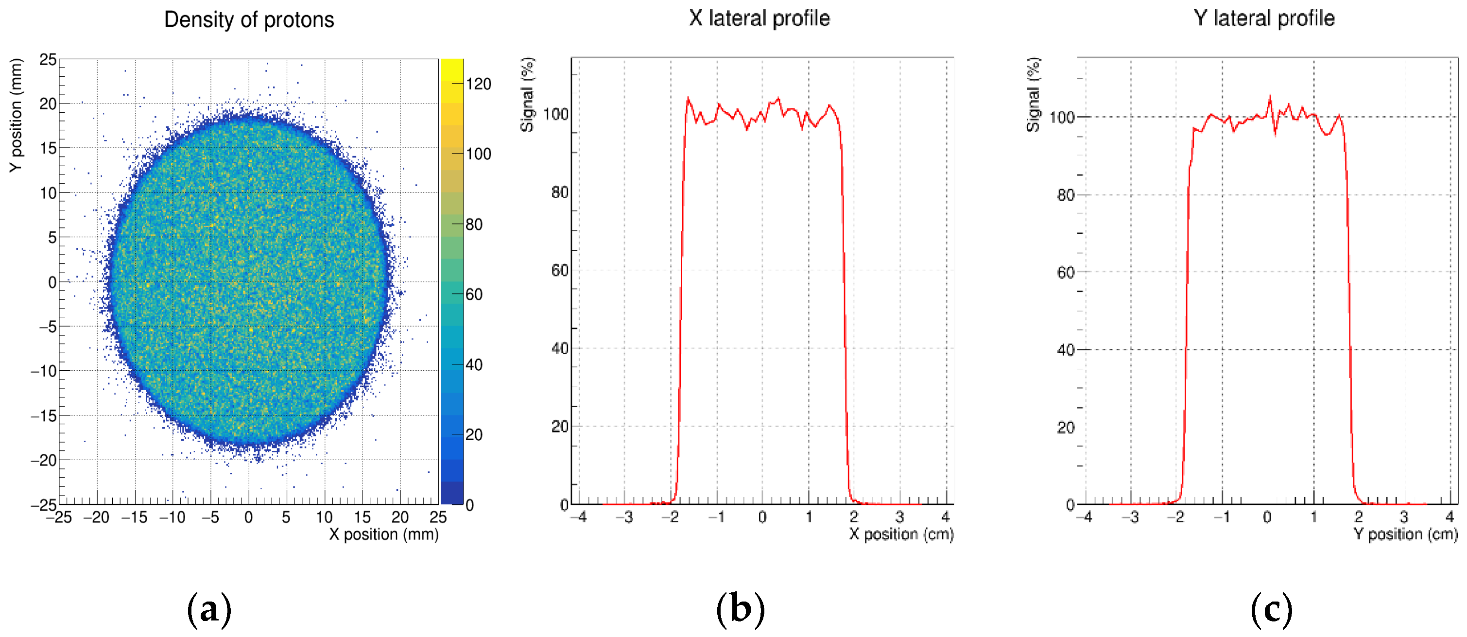
3.1. Lateral Profiles
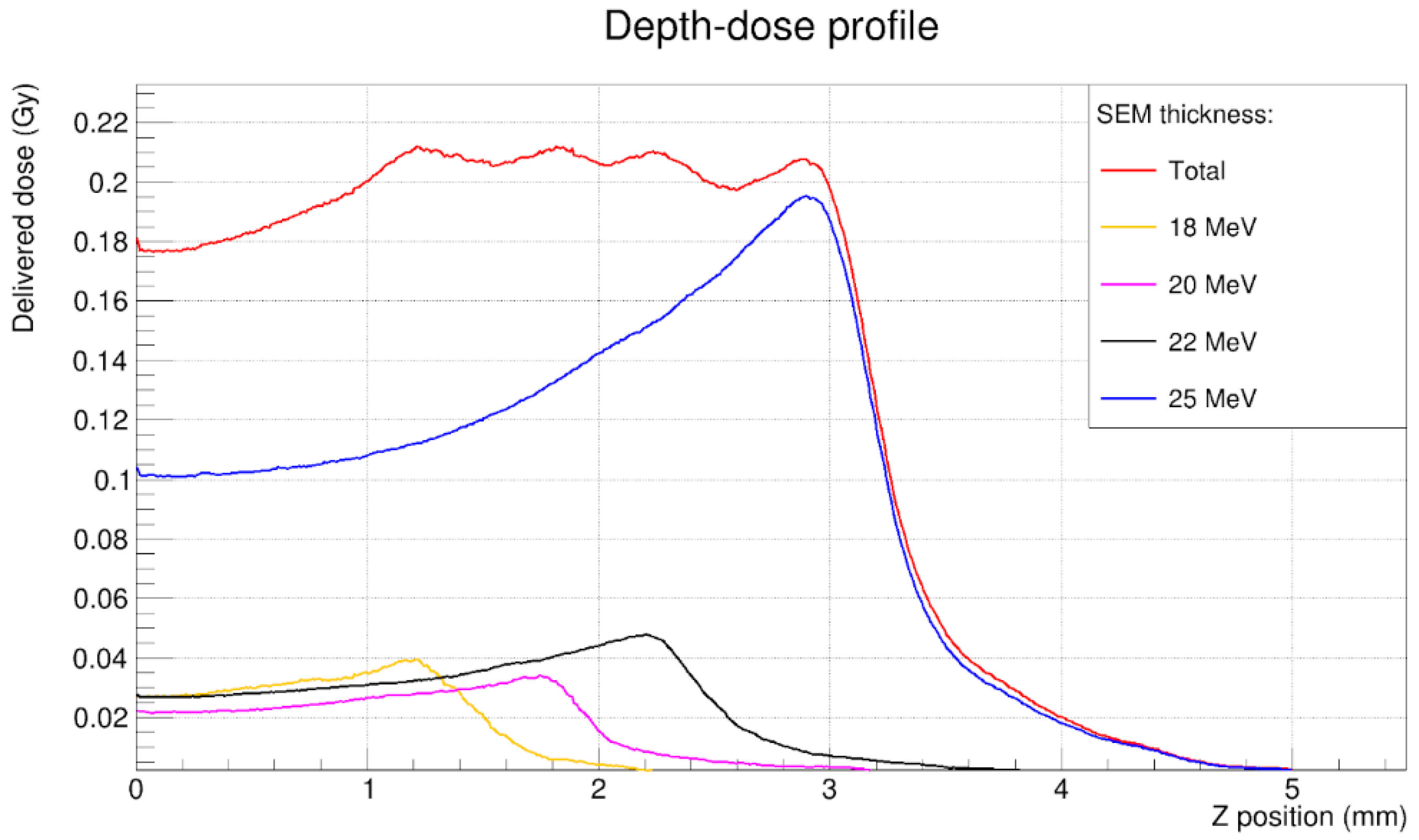
3.2. Depth-Dose Profile
3.3. Transmission Efficiency
3.4. Transmission of Unwanted Ion Species
4. Discussion
Author Contributions
Funding
Data Availability Statement
Conflicts of Interest
References
- Macchi, A.; Borghesi, M.; Passoni, M. Ion acceleration by superintense laser-plasma interaction. Rev. Mod. Phys. 2013, 85, 751–793. [Google Scholar] [CrossRef] [Green Version]
- Favaudon, V.; Caplier, L.; Monceau, V.; Pouzoulet, F.; Sayarath, M.; Fouillade, C.; Poupon, M.F.; Brito, I.; Hupé, P.; Bourhis, J.; et al. Ultrahigh dose-rate FLASH irradiation increases the differential response between normal and tumor tissue in mice. Sci. Transl. Med. 2014, 6, 245ra93. [Google Scholar] [CrossRef]
- Vozenin, M.C.; Hendry, J.H.; Limoli, C.L. Biological Benefits of Ultra-high Dose Rate FLASH Radiotherapy: Sleeping Beauty Awoken. Clin. Oncol. 2019, 31, 407–415. [Google Scholar] [CrossRef]
- Margarone, D.; Cirrone, G.; Cuttone, G.; Amico, A.; Andò, L.; Borghesi, M.; Bulanov, S.; Bulanov, S.; Chatain, D.; Fajstavr, A.; et al. ELIMAIA: A Laser-Driven Ion Accelerator for Multidisciplinary Applications. Quantum Beam Sci. 2018, 2, 8. [Google Scholar] [CrossRef] [Green Version]
- Cirrone, G.A.P.; Romano, F.; Scuderi, V.; Amato, A.; Candiano, G.; Cuttone, G.; Giove, D.; Korn, G.; Krasa, J.; Leanza, R.; et al. Transport and dosimetric solutions for the ELIMED laser-driven beam line. Nucl. Instruments Methods Phys. Res. Sect. A Accel. Spectrometers Detect. Assoc. Equip. 2015, 796, 99–103. [Google Scholar] [CrossRef]
- Cirrone, G.A.P.; Petringa, G.; Catalano, R.; Schillaci, F.; Allegra, L.; Amato, A.; Avolio, R.; Costa, M.; Cuttone, G.; Fajstavr, A.; et al. ELIMED-ELIMAIA: The First Open User Irradiation Beamline for Laser-Plasma-Accelerated Ion Beams. Front. Phys. 2020, 8, 564907. [Google Scholar] [CrossRef]
- Schillaci, F.; Cirrone, G.A.P.; Cuttone, G.; Maggiore, M.; Andó, L.; Amato, A.; Costa, M.; Gallo, G.; Korn, G.; Larosa, G.; et al. Design of the ELIMAIA ion collection system. J. Instrum. 2015, 10, T12001. [Google Scholar] [CrossRef]
- Schillaci, F.; Maggiore, M.; Andó, L.; Cirrone, G.A.P.; Cuttone, G.; Romano, F.; Scuderi, V.; Allegra, L.; Amato, A.; Gallo, G.; et al. Design of a large acceptance, high efficiency energy selection system for the ELIMAIA beam-line. J. Instrum. 2016, 11, P08022. [Google Scholar] [CrossRef]
- Petringa, G.; Cirrone, G.A.P.; Catalano, R.; Cuttone, G.; Miluzzo, G.; Schillaci, F.; Tudisco, S.S.; Margarone, D. Status of the ELIMED-ELIMAIA beamline and innovative development of dosimetric devices for laser-driven ion beams. In Proceedings of the Applying Laser-Driven Particle Acceleration II, Medical and Nonmedical Uses of Distinctive Energetic Particle and Photon Sources: SPIE Optics + Optoelectronics Industry Event; Bolton, P.R., Ed.; SPIE: Bellingham, WA, USA, 2021; Volume 11790, p. 11. [Google Scholar]
- Scuderi, V.; Amato, A.; Amico, A.; Borghesi, M.; Cirrone, G.; Cuttone, G.; Fajstavr, A.; Giuffrida, L.; Grepl, F.; Korn, G.; et al. Diagnostics and Dosimetry Solutions for Multidisciplinary Applications at the ELIMAIA Beamline. Appl. Sci. 2018, 8, 1415. [Google Scholar] [CrossRef] [Green Version]
- Margarone, D.; Krsa, J.; Giuffrida, L.; Picciotto, A.; Torrisi, L.; Nowak, T.; Musumeci, P.; Velyhan, A.; Prokpek, J.; Lska, L.; et al. Full characterization of laser-accelerated ion beams using Faraday cup, silicon carbide, and single-crystal diamond detectors. J. Appl. Phys. 2011, 109, 103302. [Google Scholar] [CrossRef]
- Scuderi, V.; Milluzzo, G.; Doria, D.; Alejo, A.; Amico, A.G.; Booth, N.; Cuttone, G.; Green, J.S.; Kar, S.; Korn, G.; et al. TOF diagnosis of laser accelerated, high-energy protons. Nucl. Instruments Methods Phys. Res. Sect. A Accel. Spectrometers Detect. Assoc. Equip. 2020, 978, 164364. [Google Scholar] [CrossRef]
- Brahme, A.; Chavaudra, J.; McCullogh, E.; Nüsllin, F.; Rawlinson, J.E.; Svensson, G.; Svensson, H. Accuracy requirements and quality assurance of external beam therapy with photons and electrons. Acta Oncol. 1988, 27 (Suppl. 1). [Google Scholar]
- Goitein, M. Calculation of the uncertainty in the dose delivered during radiation therapy. Med. Phys. 1985, 12, 608–612. [Google Scholar] [CrossRef]
- Mijnheer, B.J.; Battermann, J.J.; Wambersie, A. What degree of accuracy is required and can be achieved in photon and neutron therapy? Radiother. Oncol. 1987, 8, 237–252. [Google Scholar] [CrossRef]
- Pipek, J.; Romano, F.; Milluzzo, G.; Cirrone, G.A.P.; Cuttone, G.; Amico, A.G.; Margarone, D.; Larosa, G.; Leanza, R.; Petringa, G.; et al. Monte Carlo simulation of the ELIMED beamline using Geant4. J. Instrum. 2017, 12, C03027. [Google Scholar] [CrossRef]
- Milluzzo, G.; Pipek, J.; Amico, A.G.; Cirrone, G.A.P.; Cuttone, G.; Korn, G.; Larosa, G.; Leanza, R.; Margarone, D.; Petringa, G.; et al. Transversal dose distribution optimization for laser-accelerated proton beam medical applications by means of Geant4. Phys. Medica 2018, 54, 166–172. [Google Scholar] [CrossRef] [PubMed]
- Milluzzo, G.; Pipek, J.; Amico, A.G.; Cirrone, G.A.P.; Cuttone, G.; Korn, G.; Larosa, G.; Leanza, R.; Margarone, D.; Petringa, G.; et al. Geant4 simulation of the ELIMED transport and dosimetry beam line for high-energy laser-driven ion beam multidisciplinary applications. Nucl. Instruments Methods Phys. Res. Sect. A Accel. Spectrometers Detect. Assoc. Equip. 2018, 909, 298–302. [Google Scholar] [CrossRef]
- Agostinelli, S.; Allison, J.; Amako, K.; Apostolakis, J.; Araujo, H.; Arce, P.; Asai, M.; Axen, D.; Banerjee, S.; Barrand, G.; et al. GEANT4—A simulation toolkit. Nucl. Instruments Methods Phys. Res. Sect. A Accel. Spectrometers Detect. Assoc. Equip. 2003, 506, 250–303. [Google Scholar] [CrossRef] [Green Version]
- Allison, J.; Amako, K.; Apostolakis, J.; Araujo, H.; Dubois, P.A.; Asai, M.; Barrand, G.; Capra, R.; Chauvie, S.; Chytracek, R.; et al. Geant4 developments and applications. IEEE Trans. Nucl. Sci. 2006, 53, 270–278. [Google Scholar] [CrossRef] [Green Version]
- Allison, J.; Amako, K.; Apostolakis, J.; Arce, P.; Asai, M.; Aso, T.; Bagli, E.; Bagulya, A.; Banerjee, S.; Barrand, G.; et al. Recent developments in GEANT4. Nucl. Instruments Methods Phys. Res. Sect. A Accel. Spectrometers Detect. Assoc. Equip. 2016, 835, 186–225. [Google Scholar] [CrossRef]
- Raschke, S.; Spickermann, S.; Toncian, T.; Swantusch, M.; Boeker, J.; Giesen, U.; Iliakis, G.; Willi, O.; Boege, F. Ultra-short laser-accelerated proton pulses have similar DNA-damaging effectiveness but produce less immediate nitroxidative stress than conventional proton beams. Sci. Rep. 2016, 6, 1–9. [Google Scholar] [CrossRef] [PubMed] [Green Version]
- Dromey, B.; Coughlan, M.; Senje, L.; Taylor, M.; Kuschel, S.; Villagomez-Bernabe, B.; Stefanuik, R.; Nersisyan, G.; Stella, L.; Kohanoff, J.; et al. Picosecond metrology of laser-driven proton bursts. Nat. Commun. 2016, 7, 1–6. [Google Scholar] [CrossRef] [PubMed]
- Amato, E.; Italiano, A.; Margarone, D.; Pagano, B.; Baldari, S.; Korn, G. Future laser-accelerated proton beams at ELI-Beamlines as potential source of positron emitters for PET. J. Instrum. 2016, 11, C04007. [Google Scholar] [CrossRef]
- Italiano, A.; Amato, E.; Margarone, D.; Psikal, J.; Korn, G.; Nazionale, I.; Catania, S. Laser-accelerated Proton Beams from a Solid Hydrogen Target as a Future Source of Radionuclides for Positron Emission Tomography. J. Sci. Eng. Res. 2017, 4, 173–176. [Google Scholar]
- Mirani, F.; Maffini, A.; Casamichiela, F.; Pazzaglia, A.; Formenti, A.; Dellasega, D.; Russo, V.; Vavassori, D.; Bortot, D.; Huault, M.; et al. Integrated quantitative PIXE analysis and EDX spectroscopy using a laser-driven particle source. Sci. Adv. 2021, 7, eabc8660. [Google Scholar] [CrossRef] [PubMed]
- Asavei, T.; Tomut, M.; Bobeica, M.; Aogaki, S.; Cernaianu, M.O.; Ganciu, M. Materials in extreme environments dor energy, accelerators and space applications at ELI-NP facilities like the Facility for Antiproton and Ion Research (FAIR), the High Luminosity Large Hadron Collider (HL-LHC), the Facility for Rare Isotope Beams. Rom. Rep. Phys. 2016, 68, 275–347. [Google Scholar]
- Barberio, M.; Scisciò, M.; Vallières, S.; Cardelli, F.; Chen, S.N.; Famulari, G.; Gangolf, T.; Revet, G.; Schiavi, A.; Senzacqua, M.; et al. Laser-accelerated particle beams for stress testing of materials. Nat. Commun. 2018, 9, 1–7. [Google Scholar] [CrossRef] [Green Version]
- Kiriyama, H.; Mori, M.; Pirozhkov, A.S.; Ogura, K.; Sagisaka, A.; Kon, A.; Esirkepov, T.Z.; Hayashi, Y.; Kotaki, H.; Kanasaki, M.; et al. High-contrast, high-intensity petawatt-class laser and applications. IEEE J. Sel. Top. Quantum Electron. 2015, 21, 232–249. [Google Scholar] [CrossRef]
- Dover, N.P.; Nishiuchi, M.; Sakaki, H.; Kondo, K.; Alkhimova, M.A.; Faenov, A.Y.; Hata, M.; Iwata, N.; Kiriyama, H.; Koga, J.K.; et al. Effect of Small Focus on Electron Heating and Proton Acceleration in Ultrarelativistic Laser-Solid Interactions. Phys. Rev. Lett. 2020, 124, 084802. [Google Scholar] [CrossRef] [Green Version]
- Jia, S.B.; Romano, F.; Cirrone, G.A.P.; Cuttone, G.; Hadizadeh, M.H.; Mowlavi, A.A.; Raffaele, L. Designing a range modulator wheel to spread-out the Bragg peak for a passive proton therapy facility. Nucl. Instruments Methods Phys. Res. Sect. A Accel. Spectrometers Detect. Assoc. Equip. 2015, 806, 101–108. [Google Scholar] [CrossRef]
- Kostjuchenko, V.; Nichiporov, D.; Luckjashin, V. A compact ridge filter for spread out Bragg peak production in pulsed proton clinical beams. Med. Phys. 2001, 28, 1427–1430. [Google Scholar] [CrossRef] [PubMed]
- Musolino, S.V. Absorbed Dose Determination in External Beam Radiotherapy: An International Code of Practice for Dosimetry Based on Standards of Absorbed Dose to Water; Technical Reports Series No. 398. Health Phys. 2001, 81, 592–593. [Google Scholar] [CrossRef]
- Catalano, R.; Petringa, G.; Cuttone, G.; Bonanno, V.P.; Chiappara, D.; Musumeci, M.S.; Puglia, S.M.R.; Stella, G.; Scifoni, E.; Tommasino, F.; et al. Transversal dose profile reconstruction for clinical proton beams: A detectors inter-comparison. Phys. Medica 2020, 70, 133–138. [Google Scholar] [CrossRef] [PubMed]
- Cirrone, G.A.P.; Coco, S.; Cuttone, G.; De Martinis, C.; Giove, D.; Lojacono, P.A.; Mauri, M.; Messina, R. A fast monitoring system for radiotherapeutic proton beams based on scintillating screens and a CCD camera. IEEE Trans. Nucl. Sci. 2004, 51, 1402–1406. [Google Scholar] [CrossRef]
- Sistrunk, E.; Spinka, T.; Bayramian, A.; Betts, S.; Bopp, R.; Buck, S.; Charron, K.; Cupal, J.; Deri, R.; Drouin, M.; et al. All diode-pumped, high-repetition-rate advanced petawatt laser system (HAPLS). In Proceedings of the 2017 Conference on Lasers and Electro-Optics, CLEO 2017—Proceedings; Institute of Electrical and Electronics Engineers Inc.: Piscataway, NJ, USA, 2017; Volume 2017, pp. 1–2. [Google Scholar]
- ICRU. Key data for ionizing-radiation dosimetry: Measurements standards and applications (ICRU Report 90). J. Int. Comm. Radiat. Units Meas. 2016, 14. NP. Available online: http://fulir.irb.hr/3302/ (accessed on 10 September 2021).
- Wiedemann, H. Particle Accelerator Physics, Graduate Texts in Physics; Springer International Publishing: Cham, Switzerland, 2015; ISBN 978-3-319-18316-9. [Google Scholar]


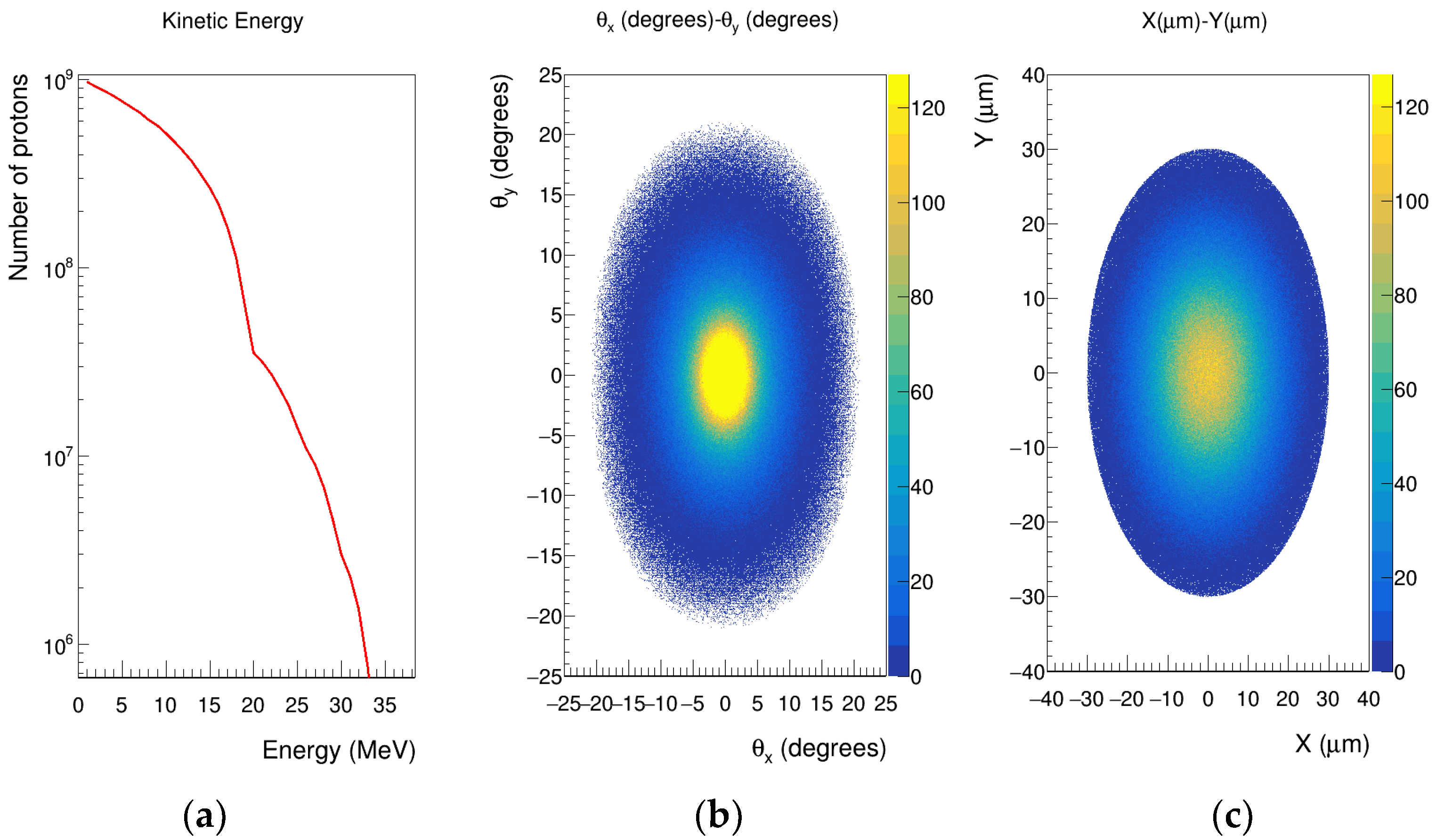
| Xθx | Yθy | XY | |
| α | 0.8401 | 0.3556 | 0.0002 |
| β (mm/π·mrad) | 2.7094 | 2.4484 | 0.9112 |
| Emit. Norm (rms) π mm·mrad | 2.9506 | 3.9324 | 24.15 mm2 |
| Xmax | Ymax | θx, max | θy, max |
| 14.97 mm | 14.99 mm | 8.632 mrad | 7.162 mrad |
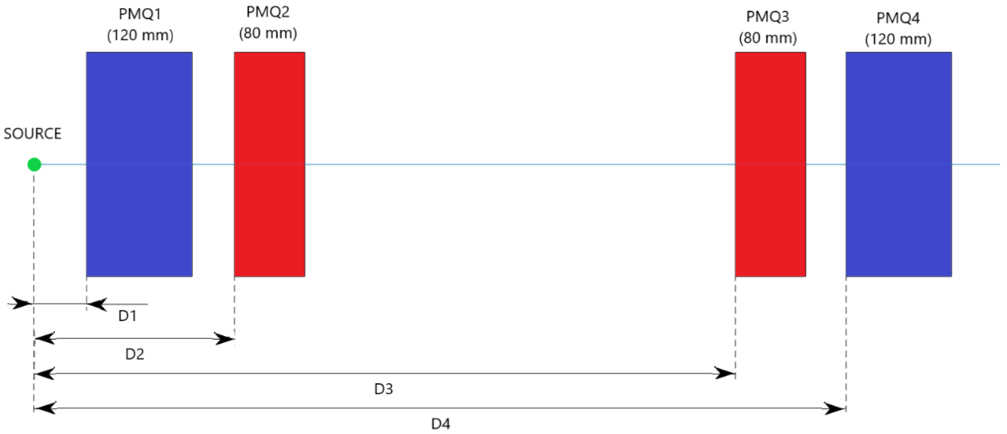
| Energy (MeV) | D1 (mm) | D2 (mm) | D3 (mm) | D4 (mm) |
|---|---|---|---|---|
| 18 | 56.8 | 218.4 | 772.0 | 901.1 |
| 20 | 60.2 | 228.3 | 798.2 | 924.0 |
| 22 | 59.4 | 253.1 | 836.2 | 956.2 |
| 25 | 61.5 | 281.7 | 885.5 | 1005.5 |
| Parameter | Tolerance | X Profile | Y Profile |
|---|---|---|---|
| FWHM | As close as possible to the beam diameter | 3.57 cm | 3.56 cm |
| Left penumbra | ≤1.5 mm | 0.85 mm | 0.91 mm |
| Right penumbra | ≤1.5 mm | 0.82 mm | 0.96 mm |
| Ratio 90%/50% | >0.9 | 0.96 | 0.95 |
| Flatness | ≤3% | 4.1% | 4.7% |
| Symmetry | 97–103% | 101.2% | 100.1% |
| Parameter | Tolerance | Result |
|---|---|---|
| M95 | ≥1 mm | 1.96 mm |
| Distal fall-off | <1.5 mm | 0.94 mm |
| Flatness | <5% | 3.6% |
| Energy (MeV) | After PMQs (%) | After ESS (%) | After Kapton Window (%) | Final (%) |
|---|---|---|---|---|
| 18 | 39 | 2.93 | 2.67 | 0.37 |
| 20 | 42.7 | 6.38 | 5.77 | 0.91 |
| 22 | 37.1 | 6.56 | 6.2 | 0.81 |
| 25 | 34.4 | 6.31 | 5.98 | 0.75 |
Publisher’s Note: MDPI stays neutral with regard to jurisdictional claims in published maps and institutional affiliations. |
© 2021 by the authors. Licensee MDPI, Basel, Switzerland. This article is an open access article distributed under the terms and conditions of the Creative Commons Attribution (CC BY) license (https://creativecommons.org/licenses/by/4.0/).
Share and Cite
Mingo Barba, S.; Schillaci, F.; Catalano, R.; Petringa, G.; Margarone, D.; Cirrone, G.A.P. Dosimetric Optimization of a Laser-Driven Irradiation Facility Using the G4-ELIMED Application. Appl. Sci. 2021, 11, 9823. https://doi.org/10.3390/app11219823
Mingo Barba S, Schillaci F, Catalano R, Petringa G, Margarone D, Cirrone GAP. Dosimetric Optimization of a Laser-Driven Irradiation Facility Using the G4-ELIMED Application. Applied Sciences. 2021; 11(21):9823. https://doi.org/10.3390/app11219823
Chicago/Turabian StyleMingo Barba, Sergio, Francesco Schillaci, Roberto Catalano, Giada Petringa, Daniele Margarone, and Giuseppe Antonio Pablo Cirrone. 2021. "Dosimetric Optimization of a Laser-Driven Irradiation Facility Using the G4-ELIMED Application" Applied Sciences 11, no. 21: 9823. https://doi.org/10.3390/app11219823
APA StyleMingo Barba, S., Schillaci, F., Catalano, R., Petringa, G., Margarone, D., & Cirrone, G. A. P. (2021). Dosimetric Optimization of a Laser-Driven Irradiation Facility Using the G4-ELIMED Application. Applied Sciences, 11(21), 9823. https://doi.org/10.3390/app11219823