Abstract
In the detection of small size mass loading, such as a single cell, a micro droplet or an aerosol particle, the sensors with longitudinally coupled surface acoustic wave resonator (LC-SAWR) structure can hardly avoid waveform distortions. The relative size of mass loading to the sensitive surface of the detector is the main factor affecting the response of LC-SAWR. The smaller the relative size, the worse the waveform distortion. In order to avoid influences from the mass loading’s size, in this paper, a transversely coupled SAW resonator (TC-SAWR) was proposed in order to achieve high performance in sensing small size mass loadings. For the design and simulation of TC-SAWR, the two-dimensional coupling of model (2D-COM) theory and finite element method (FEM) were used in this work. In the experiment, SiO2 was deposited on the sensor’s surface as a small size mass loading. The results from simulation and experiment mutually demonstrated the advantage of TC-SAWR to conquer waveform distortion in the detection of small size mass loading.
1. Introduction
The surface acoustic wave resonator (SAWR) was used mainly as an extremely narrow-band filter until Martin reported its use to measure chemical vapors [1]. Since then, SAWRs have been widely used in the field of sensing for their advantages such as low loss, high sensitivity and stability. In recent years, SAWRs have received more attention in the field of biosensing, especially in the measurement of small mass loading [2,3]. According to the resonance mode, SAWR could be sorted as a longitudinally coupled SAW resonator (LC-SAWR) and transversely coupled resonator (TC-SAWR). Normally, researchers take LC-SAWRs as sensor chips such as vapor detector [4], mass microbalance [5], PM2.5 detector [6], strain sensor [7,8] and temperature sensors [9]. In these cases, the physical quantities measured were uniformly exerted on the surface of the acoustic wave device. However, in biological detection, the substances measured, such as cells and proteins, are of small size; thus, it is difficult for these substances to completely and uniformly cover the surface of the detector [10,11,12,13]. In our previous work, we have discussed the effect of non-uniformly distributed loads on the LC-SAWR’s response, which showed waveform distortions caused by small size mass loadings [14]. In order to achieve high performance in the sensing of small size mass loading, a TC-SAWR was proposed in this paper as a detector in order to conquer waveform distortion.
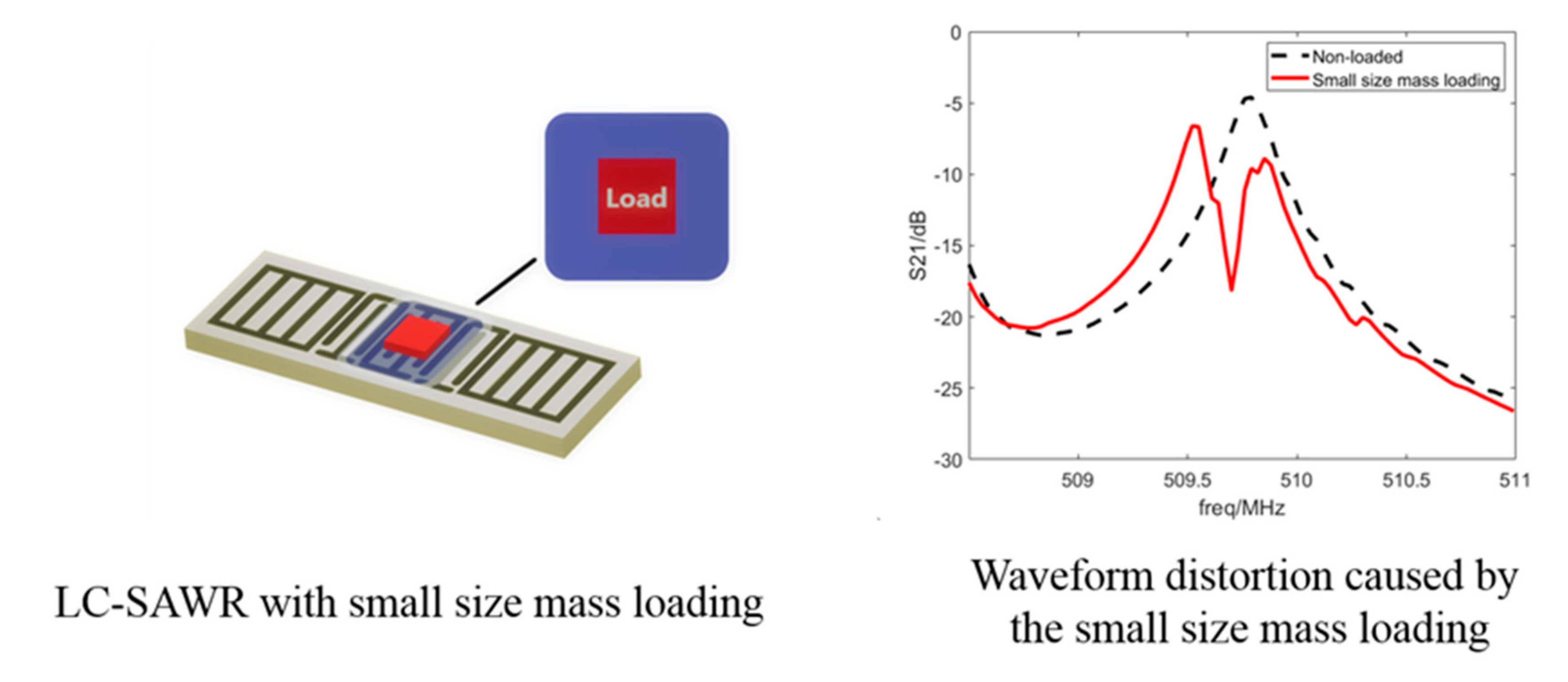
When a LC-SAWR is working at its resonate mode, the device could be modeled as a combination of several independent channels [14]. If the load does not fully cover the device’s aperture, it can only be applied to part of the channels. Then, the overall response of the device would be composed of the loaded channels’ responses and the non-loaded channels’ responses. The center frequency of the loaded channel is lower than that of the no-loaded channel, resulting in waveform distortion. (Figure 1). For TC-SAWR, the acoustic wave resonates transversely in the aperture, forming resonance peaks of each mode (Figure 2). In this case, the device cannot be divided into multiple independent channels and needs to be analyzed integrally. As a result, the load acting on the TC-SAWR will change the resonance frequency of each mode, regardless of whether it covers the aperture completely or not, which avoids waveform distortion caused by the small size load.
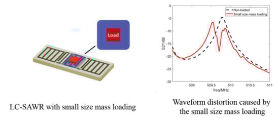
Figure 1.
LC-SAWR with small size mass loading (left) and the waveform distortion (right).
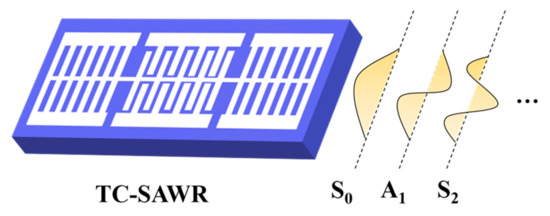
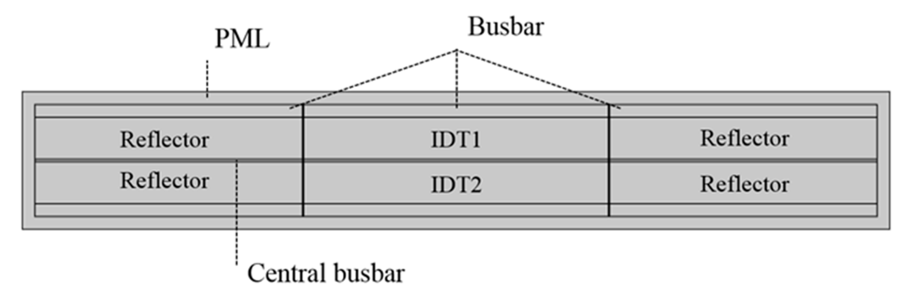
Figure 2.
Basic structure of TC-SAWR and its transverse resonance modes.
In the past, the one-dimensional coupled mode theory (1D-COM) has been used for the simulation and design of TC-SAWRs [15,16]. However, this method can only compute a limited number of transverse modes; thus, it is not accurate enough to simulate the response of TC-SAWR. In addition, the 1D-COM theory is difficult with respect to modeling and simulating the device with small size loads. To solve these problems, we used the two-dimensional coupling-of-modes theory (2D-COM) and the finite element method (FEM) in order to obtain a more accurate simulation of TC-SAWR and to calculate the influence of small size loads on it.
The experiment was implemented in this work to verify the simulation result. In the experiment, TC-SAWR with a SiO2 cylinder attached to its surface was fabricated and measured.
In this work, the effect of small size load attached to the TC-SAWR sensors were studied theoretically and experimentally. They consistently showed that the frequency response curve of TC-SAWR had no distortion under small size load, which illustrated the advantage of TC-SAWR in the field of biochemical detection.
2. Materials and Methods
2.1. Two-Dimensional Coupling-of-Modes Theory
The two-dimensional coupling-of-modes theory (2D-COM) is a simulation method of surface acoustic wave devices by considering the diffraction effect. It was originally proposed by Haus to analyze the waveguide effect (transverse mode) of surface acoustic wave devices [17]. The TC-SAWR works in the transverse resonant modes; thus, the 2D-COM theory is very suitable for its simulation. Recently, Xiao et al. proposed a new general biquadratic form of 2D-COM equations, which further improved the simulation accuracy of this method [18]. In this paper, the 2D-COM equations of biquadratic form were used. The equations are shown in Equation (1).
Here, and stands for the particle displacements of waves propagating forward and backward directions, respectively; and is the wave number according to the electric period of the IDT. are the parameters for characterizing the anisotropy of the piezoelectric substrate; ,,, and represent coupling coefficient, excitation coefficient, static capacitance, input voltage and current.
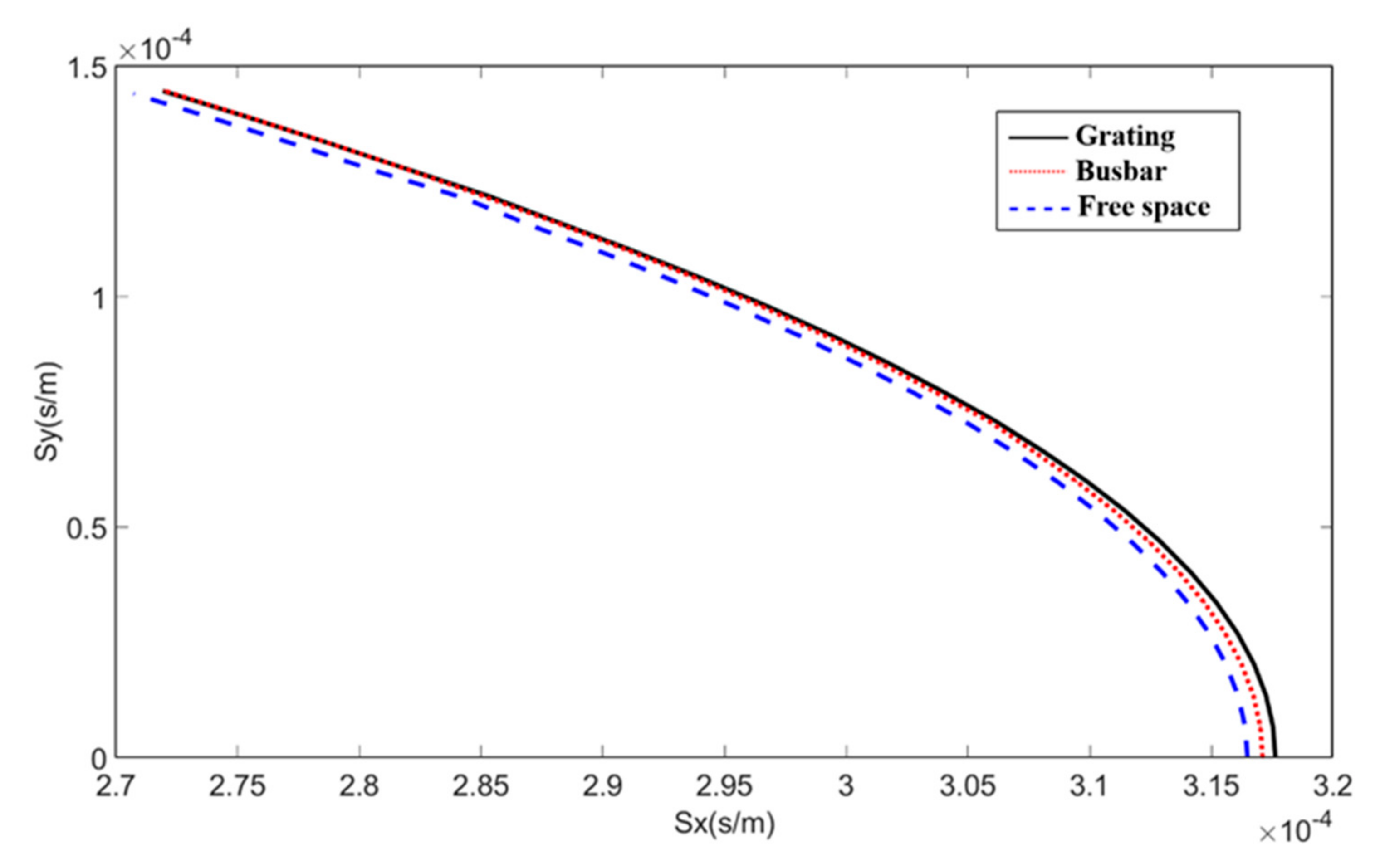
The parameters can be obtained by calculating the second and fourth derivatives at the zero point of the slowness curve [18,19]. The slowness curves of each region of the device with Al/ST-X Quartz structure are shown in Figure 3.
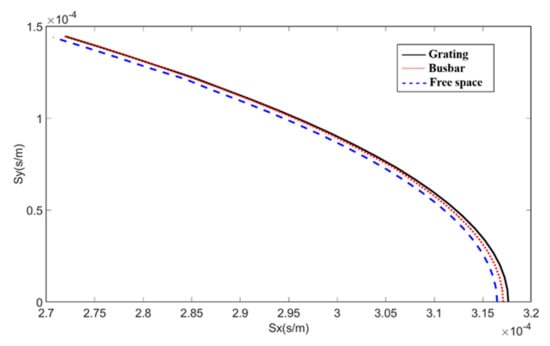
Figure 3.
Slowness curves of each region of the TC-SAWR device.
The values of in different regions were further obtained, as shown in Table 1.

Table 1.
Anisotropic parameters and of each region.
The parameters such as velocity, coupling coefficient, excitation coefficient and static capacitance were determined by using the finite element method [20], as shown in Table 2.
Table 2.
COM parameters.
All the above parameters were close to the values reported in the other literature [8,18] (the subtle differences were caused by factors such as substrate material, device structure and calculation accuracy).
2.2. PDE Modeling of Transversely Coupled SAW Resonator
The 2D-COM equations can be numerically solved by the PDE module of COMSOL Multiphysics [21]. Firstly, the geometric model of TC-SAWR was established, as shown in Figure 4. The substrate material and structural parameters of the model are listed in Table 3.

Figure 4.
Geometric model of TC-SAWR constructed in COMSOL.
Table 3.
The substrate material and structural parameters of TC-SAWR.
Here, IDT1 and IDT2 are the input and output ports, respectively.
After the geometric model is meshed properly, the 2D-COM equations would be solved by the finite element method. Figure 5 demonstrates the calculated transverse modes of order 1~4, respectively.
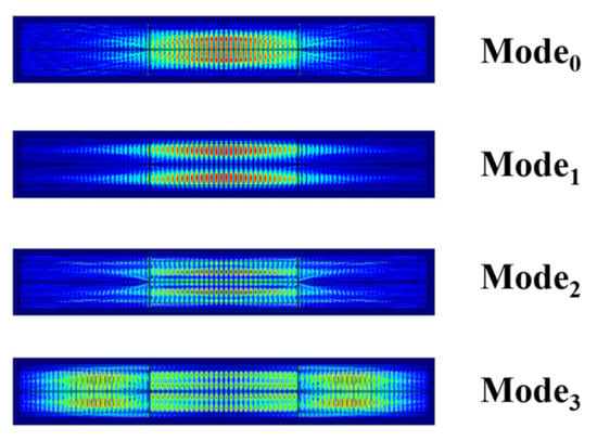
Figure 5.
Transverse modes of order 1~4.
The port current should be calculated by the following integral.
The description of variables in Equation (2) is written above (line 86 to 90).
Once the port current is determined, the insertion loss (S21) of TC-SAWR is obtained.
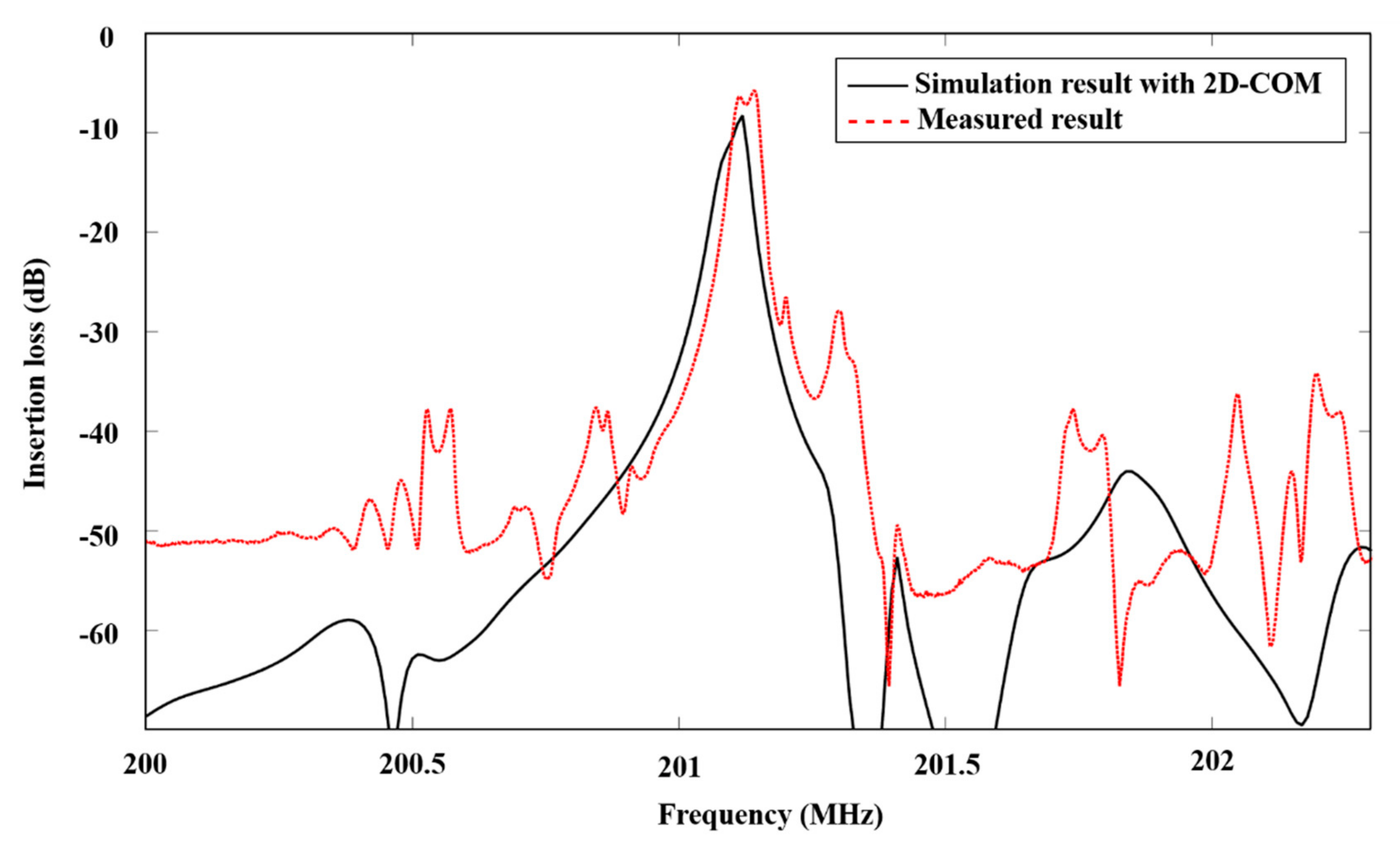
The parameter S21 of the fabricated TC-SAWR device was measured by a VNA (Agilent E5071B Network analyzer). The frequency response of S21 is shown in Figure 6. The measured and calculated center frequencies were 201.13 MHz and 201.11 MHz, respectively. The measured result was in good agreement with the simulation.
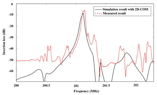
Figure 6.
Insertion loss (S21) of TC-SAWR calculated by using 2D-COM (black solid curve) and measured (red dotted curve).
3. Result and Discussion
In order to study the effect of small-size mass loading on the response of TC-SAWR device, we designed a SiO2 cylinder with a diameter of 100 μm and a height of 300 nm attached to the device surface, as shown in Figure 7.

Figure 7.
TC-SAWR device with a SiO2 cylinder attached to its surface.
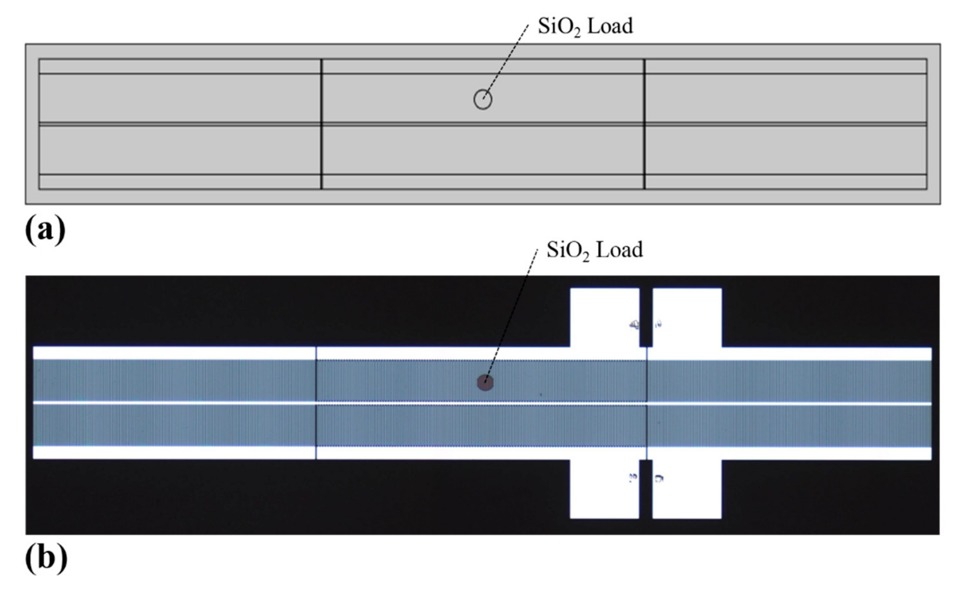
The attachment site was located at the central point of IDT1. The simulation model and the photo of fabricated TC-SAWR device are shown in Figure 8.
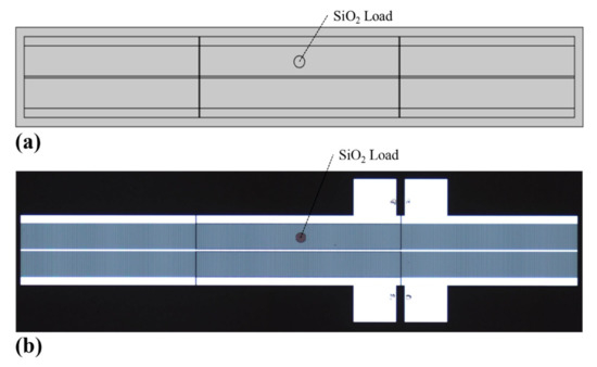
Figure 8.
(a) Geometric model of TC-SAWR with SiO2 load constructed in COMSOL; (b) fabricated TC-SAWR device with SiO2 load.
Figure 9 and Figure 10 showed the simulated and measured results of frequency response with and without SiO2 load, respectively. They consistently showed that the frequency response curve of TC-SAWR had no distortion under small size load.
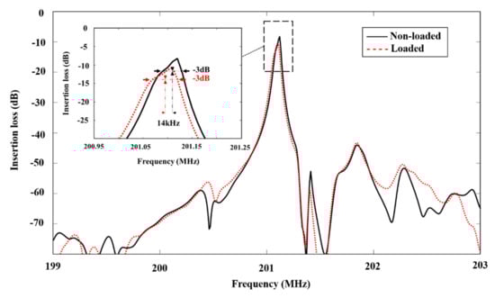
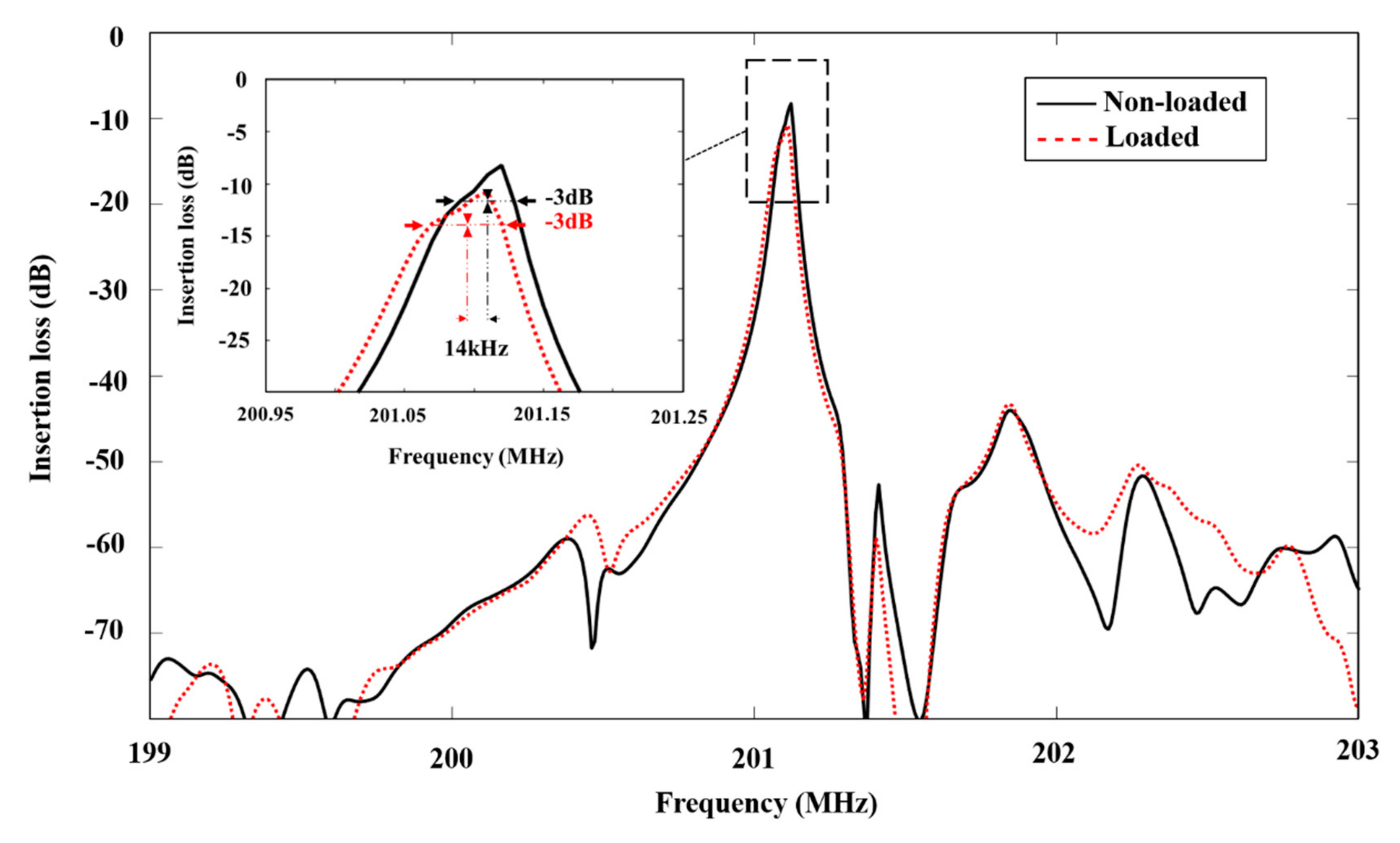
Figure 9.
Simulation result of the frequency response before and after loading.

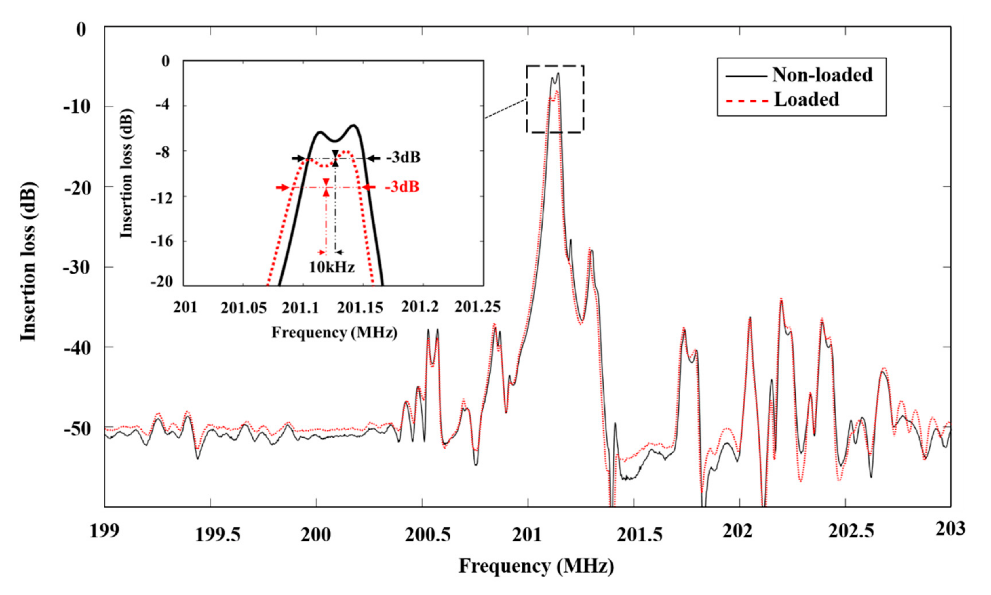
Figure 10.
Measured result of the frequency response before and after loading.
More specifically, under the effect of mass loading, the insertion loss increased around 2 dB, and the center frequency shifted around 14 kHz in the simulation result. On the other hand, the insertion loss increased by 2 dB, and the center frequency shifted around 10 kHz in the measured result. The differences between simulation and experimental results were caused by multiple factors, such as the thickness error of SiO2 load, the fabrication error of SAW chip and the solution accuracy of the 2-D COM theory.
Furthermore, there was a larger passband ripple in the measured frequency response. According to the analysis in previous sections, the main peak of TC- SAWR’s frequency response was composed of the 0-order symmetric resonant mode (S0) and the 1-order antisymmetric resonant mode (A1), which means that the passband ripple was caused by the large frequency difference between two resonant modes. The deviation of resonant modes’ frequencies mainly depends on the width of the central busbar and the aperture size of the TC-SAWR. In order to reduce the frequency difference between the two resonant modes and increase the Q-value of TC-SAWR, optimizations of the structure will be deployed in the future.
4. Conclusions
In the field of biosensors, small sizes of substances to be measured, such as cells and proteins, are common. However, small size loads often cause waveform distortion in longitudinally coupled resonators (LC-SAWR) and other sensitive chips. Further analysis shows that the cause of the waveform distortion is that the small size loads cannot completely cover the sensitive area of LC-SAWR, resulting in uneven load distributions on the surface of the sensor. In order to suppress the waveform distortion caused by the small size load, a transversely coupled SAW resonator (TC-SAWR) was designed and fabricated in this paper. For TC-SAWR, acoustic wave resonates transversely in its aperture, and the mass loading acting on the TC-SAWR will change the resonance frequency of each transverse mode, regardless of whether it covers the aperture completely or not, which avoids waveform distortions caused by the small size loads.
On the other hand, accurate simulation of TC-SAWR has been a difficult problem for a long time. In this paper, 2D-COM theory and the finite element method were used to realize the precise simulation of TC-SAWR. The COM-parameters and the anisotropic parameters were calculated, then the 2D-COM equations of TC-SAWR were established. Finally, by using the PDE module of COMSOL, the 2D-COM equations could be solved numerically, and the response of TC-SAWR under SiO2 load was obtained.
For comparison and verification, TC-SAWR with a SiO2 cylinder attached to its surface was fabricated and measured. Both the simulation result and the experiment result confirmed the effectiveness of the TC-SAWR device to conquer waveform distortions in the detection of small size load.
This paper illustrated the advantage of TC-SAWR in the field of biochemical detection and introduced an effective method (2D-COM combined with FEM) to simulate the device’s performance. Based on this investigation, TC-SAWR is expected to play an important role in biochemical detection.
Author Contributions
Conceptualization, R.Y. and J.L.; methodology, R.Y.; simulation, R.Y. and Z.C.; experiments, M.L. and Y.Z.; data analysis, R.Y. and J.L.; writing—original draft preparation, R.Y.; writing—review and editing, J.L. and S.H.; funding acquisition, J.L. All authors have read and agreed to the published version of the manuscript.
Funding
This research was funded by the National Natural Science Foundation of China (NO.12074404).
Institutional Review Board Statement
Not applicable.
Informed Consent Statement
Not applicable.
Acknowledgments
This research was funded by the National Natural Science Foundation of China (NO.12074404).
Conflicts of Interest
The authors declare no conflict of interest.
References
- Martin, S.J.; Schweizer, K.S.; Schwartz, S.S.; Gunshor, R.L. Vapor Sensing by Means of a ZnO-on-Si Surface Acoustic Wave Resonator. In Proceedings of the IEEE 1984 Ultrasonics Symposium, Dallas, Texas, 14–16 November 1984; pp. 207–212. [Google Scholar]
- Wang, T.; Green, R.; Nair, R.; Howell, M.; Mohapatra, S.; Guldiken, R.; Mohapatra, S. Surface Acoustic Waves (SAW)-Based Biosensing for Quantification of Cell Growth in 2D and 3D Cultures. Sensors 2015, 15, 32045–32055. [Google Scholar] [CrossRef] [PubMed]
- Mujahid, A.; Dickert, F. Surface Acoustic Wave (SAW) for Chemical Sensing Applications of Recognition Layers. Sensors 2017, 17, 2716. [Google Scholar] [CrossRef] [PubMed] [Green Version]
- Watson, G.; Staples, E. SAW Resonators as Vapor Sensors. In Proceedings of the IEEE Symposium on Ultrasonics, Honolulu, HI, USA, 4–7 December 1990; pp. 311–314. [Google Scholar]
- Bowers, W.D.; Chuan, R.L.; Duong, T.M. A 200 MHz Surface Acoustic Wave Resonator Mass Microbalance. Rev. Sci. Instrum. 1991, 62, 1624–1629. [Google Scholar] [CrossRef]
- Liu, J.; Hao, W.; Liu, M.; Liang, Y.; He, S. A Novel Particulate Matter 2.5 Sensor Based on Surface Acoustic Wave Technology. Appl. Sci. 2018, 8, 82. [Google Scholar] [CrossRef] [Green Version]
- Donohoe, B.; Geraghty, D.; O’Donnell, G.E. Wireless Calibration of a Surface Acoustic Wave Resonator as a Strain Sensor. IEEE Sens. J. 2011, 11, 1026–1032. [Google Scholar] [CrossRef]
- Wang, W.; Xue, X.; Fan, S.; Liu, M.; Liang, Y.; Lu, M. Development of a Wireless and Passive Temperature-Compensated SAW Strain Sensor. Sens. Actuators A Phys. 2020, 308, 112015. [Google Scholar] [CrossRef]
- Li, X.; Wang, W.; Fan, S.; Yin, Y.; Jia, Y.; Liang, Y.; Liu, M. Optimization of SAW Devices with LGS/Pt Structure for Sensing Temperature. Sensors 2020, 20, 2441. [Google Scholar] [CrossRef] [PubMed]
- Drbohlavová, L.; Fekete, L.; Bovtun, V.; Kempa, M.; Taylor, A.; Liu, Y.; Bou Matar, O.; Talbi, A.; Mortet, V. Love-Wave Devices with Continuous and Discrete Nanocrystalline Diamond Coating for Biosensing Applications. Sens. Actuators A Phys. 2019, 298, 111584. [Google Scholar] [CrossRef]
- Otori, H.; Higashiyama, T.; Uehara, A.; Kainuma, M.; Kudo, Y.; Kamimura, T.; Kon, T.; Mochitate, K.; Kikuchi, H.; Furuya, Y. Signal Change of Surface Acoustic Wave (SAW) Caused by H2O2 Damage to SV40-T2 Cells Cultivated on SH-SAW Sensor. Sens. Actuators A Phys. 2013, 200, 162–167. [Google Scholar] [CrossRef]
- Länge, K.; Rapp, B.E.; Rapp, M. Surface Acoustic Wave Biosensors: A Review. Anal. Bioanal. Chem. 2008, 391, 1509–1519. [Google Scholar] [CrossRef]
- Lu, X.; Cui, M.; Yi, Q.; Kamrani, A. Detection of Mutant Genes with Different Types of Biosensor Methods. TrAC Trends Anal. Chem. 2020, 126, 115860. [Google Scholar] [CrossRef]
- You, R.; Liu, J.; Liu, M.; He, S. Detecting of Non-Uniformly Distributed Loads with SAW Sensors Using a Two-Dimensional Segmentation Method. Sens. Actuators A Phys. 2021, 326, 112728. [Google Scholar] [CrossRef]
- Chen, D.P.; Schwab, M.A.; Lambert, C.; Hartmann, C.S.; Heighway, J. Heighway Precise Design Technique of SAW Transversely Coupled Resonator Filters on Quartz. In Proceedings of the IEEE Ultrasonics Symposium ULTSYM-94, Cannes, France, 25–27 May 1994; Volume 1, pp. 67–70. [Google Scholar]
- Hartmann, C.S.; Chen, D.P.; Heighway, J. Experimental Determination of COM Model Parameters for SAW Transversely Coupled Resonator Filter. In Proceedings of the IEEE 1992 Ultrasonics Symposium Proceedings, Tucson, AZ, USA, 20–23 October 1992; pp. 211–214. [Google Scholar]
- Haus, H.A. Modes in SAW Grating Resonators. J. Appl. Phys. 1977, 48, 4955–4961. [Google Scholar] [CrossRef]
- Xiao, Q.; Ji, X.; Ma, X.; Cai, P. A New General Form of 2-D Coupling-of-Modes Equations for Analysis of Waveguiding in Surface Acoustic Wave Devices. IEEE Trans. Ultrason. Ferroelect. Freq. Contr. 2020, 67, 1033–1039. [Google Scholar] [CrossRef] [PubMed]
- You, R.; Liu, J.; Liu, M.; Chen, Z.; He, S. Simulation of SAW Sensors with Various Distributed Mass Loadings Using Two-Dimensional Coupling-of-Modes Theory. Sensors 2020, 20, 7260. [Google Scholar] [CrossRef] [PubMed]
- Hao, W.; Liu, J.; Liu, M.; Liang, Y.; He, S. Mass Sensitivity Optimization of a Surface Acoustic Wave Sensor Incorporating a Resonator Configuration. Sensors 2016, 16, 562. [Google Scholar] [CrossRef] [PubMed] [Green Version]
- Tokuda, O.; Hirota, K. Two-Dimensional Coupling-of-Modes Analysis in Surface Acoustic Wave Device Performed by COMSOL Multiphysics. Jpn. J. Appl. Phys. 2011, 50, 07HD15. [Google Scholar] [CrossRef]


Publisher’s Note: MDPI stays neutral with regard to jurisdictional claims in published maps and institutional affiliations. |
© 2021 by the authors. Licensee MDPI, Basel, Switzerland. This article is an open access article distributed under the terms and conditions of the Creative Commons Attribution (CC BY) license (https://creativecommons.org/licenses/by/4.0/).