Article

Optical Injection Locking for Generation of Tunable Low-Noise Millimeter Wave and THz Signals

Department of Electrical Engineering, Eindhoven University of Technology, 5600MB Eindhoven, The Netherlands
*
Author to whom correspondence should be addressed.
Appl. Sci. 2021, 11(21), 10185; https://doi.org/10.3390/app112110185
Submission received: 10 October 2021 / Revised: 25 October 2021 / Accepted: 27 October 2021 / Published: 30 October 2021
(This article belongs to the Special Issue Applications of Millimeter-Wave and Terahertz Technologies)

Abstract

:
This article presents the experimental demonstration of synchronization of two integrated semiconductor distributed Bragg reflector lasers, fabricated with a generic multiproject wafer platform, by means of injection locking. Substantial linewidth reduction and frequency stabilization of the lasers were shown during locking of the lasers to an optical frequency comb. Phase noise was measured for different injected powers and different laser cavities. For a generation of millimeter-wave signals up to 80 GHz, two lasers were simultaneously locked to the comb. Fine-tuning was performed by tuning the repetition rate of the comb and coarse-tuning was carried out by switching to another comb line. A suppression ratio of 37 dB was achieved for unwanted comb lines. The achieved signal purity, phase noise, and suppression of unwanted components demonstrate the viability of injection locking for the generation of high-quality signals at sub-THz and THz frequencies and with substantial tunability.

1. Introduction

The terahertz and sub-terahertz regions are a modern frontier with a great scientific interest and application value behind them. Terahertz spectroscopy enables a noninvasive method for studying the properties of biological samples without violating their integrity [1,2]. The non-ionizing radiation makes it attractive for use in security cameras and sensors. At the same time, the THz region fulfills the gap between infrared free-space optics and modern wireless links. The THz band enables broadband spectra which can be used to fulfill the constantly increasing demand of modern communication links, and to provide connectivity to a rapidly growing number of devices in internet of things (IoT) or machine-to-machine (M2M) communications [3]. As such, the THz band provides unique characteristics that can be used to overcome scientific and societal challenges; however, operations with THz waves have many limitations that require additional research. These limitations are mainly related to the generation and detection of THz signals and high propagation loss in this frequency range.
There are two main approaches for the generation of THz signals—based on electronics or optoelectronic components [4,5]—and both methods have advantages and limitations. Typically electronic components allow to achieve higher output power and overcome the problem of the high, free-space propagation losses. Recent work demonstrates the generation of high-power terahertz signals at a room temperature in the 100 μ W–mW range [5,6]. It is nonetheless the case that electronic components have finite bandwidth caused by the complex chain of elements such as multipliers, which are required to generate a high-frequency signal [7,8]. The complexity of the fabrication of high-frequency and broadband waveguides also imposes restrictions and makes delivery of a signal to a radiating antenna a troublesome task, which limits possible applications. Other solutions usually rely on an optoelectronic approach based on heterodyne mixing of two optical tones, generated by a pair of semiconductor lasers [9,10]. Optoelectronic systems stand out due to their tunability, simplicity, and low propagation loss in optical fibers. The possibility and efficiency of the generation of highly tunable THz and sub-THz signals in the optical domain and transmitting them through a fiber were proven in many experiments [10,11,12]. At the same time, Ref. [13] demonstrated cointegration of lasers and a terahertz antenna on a single chip, which enables generation of highly tunable THz signals in the range of 0.15–3 THz. The main restriction of optoelectronics in the generation of sub-THz and THz signals is the low efficiency of the conversion of optical signal into electrical [14] and resulting low output power of the p-i-n and unitraveling carrier (UTC) photodiodes [9]. This problem can be solved with hybrid solutions based on combinations of the optoelectronic signal generators and electronic amplifiers for the THz signal [10]. In addition, simple optical THz generation circuits using two free-running lasers usually suffer from broad linewidths and a high level of phase noise, which makes them unsuitable for use in communications employing high-order modulation formats [4]. A similar situation is observed in THz spectroscopy if a high resolution is required for determining spectra of molecules with closely spaced or very narrow absorption or reflection lines [15].
Several techniques allow achieving high resolution with continuous-wave systems. One of them is based on quantum cascade lasers (QCL), which can provide high output power and low linewidth. However, QCL requires high temperature stability at cryogenic temperatures making it extremely difficult to use [16,17]. Another way to generate low-noise THz signals is to lock two semiconductor lasers, which decreases the linewidth of the beating tone and, consequently, the linewidth of the THz signal. This can be achieved with an optical feedback loop [18,19], but this method is limited by the bandwidth of the electronics components. The use of optical frequency combs (OFCs) for the generation of coherent optical tones is another alternative, but achieving the generation of a high-power THz signal requires additional filtering and amplification [20]. In order to overcome these limitations of OFC use while maintaining the benefits of using a wideband comb, recent work has demonstrated the implementation of optical injection locking (OIL) [21,22]. Optical injection locking is a technique of frequency and phase synchronization based on the photon–photon interaction when external light is injected into the laser cavity [23]. This method is usually used to synchronize two lasers, but it can also be used to reduce laser linewidth or to filter out a single optical tone out of the optical frequency comb [24]. In [21,22], the synchronization of monolithically integrated lasers employing OIL for sub-THz and THz signal generation was demonstrated. These are important steps for demonstrating of the feasibility of the generation of high-quality THz signals at room temperature with photonic integrated components. Integration of such transmitters on the chip is an important step towards the practical use of devices and systems due to the significant reduction in costs and power consumption and the improvement in scalability. In this regard, research on the integrated component is of considerable interest.
In this work, we measure and discuss in detail the separate effects: phase noise, fine- and coarse-tuning, and the locking range for sub-THz and THz generation. Synchronization of two monotonically integrated semiconductor lasers by means of injection locking (IL) of an optical frequency comb was demonstrated. Linewidth narrowing and frequency stabilization of the lasers were observed. Active filtering with a set of two slave lasers was demonstrated for different sets of optical lines in OFC. This method enables selection of the lines in an OFC with different frequency spacing between them and subsequently use them for generation of the sub-THz and THz signals. Phase noise performance of a single and a pair of lasers were measured. Phase noise was further analyzed for different injection ratios and different master tone offsets. Coarse- and fine-tuning mechanisms during IL were studied and discussed in detail. By providing a detailed study of injection locking and phase noise performance, this work proves the feasibility and flexibility of high-purity sub-THz and THz signals generation based on on-chip integrated lasers locked onto an optical frequency comb.
The remainder of this manuscript is structured as follows: Section 2 describes OIL and its application for generation of sub-THz and THz signals; Section 3 give an overview of the experimental setup; Section 4 demonstrates the experimental results; and Section 5 underlines the outcome of this work.

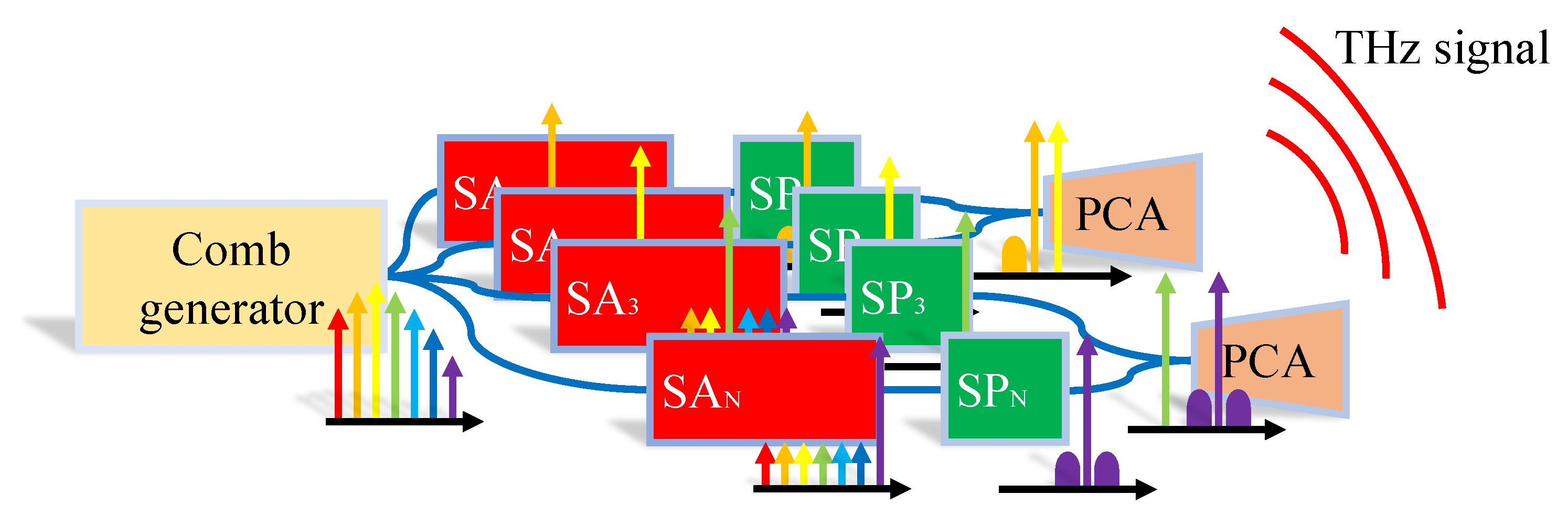
2. Optical Injection Locking for Sub-THz and THz Signal Generation

Optical injection locking, as mentioned before, is a technique of frequency and phase synchronization. Such a technique can be used in systems where frequency stability and synchronization of the lasers is crucial. OIL found use in many applications: as active filtering or so-called “selective amplification” [22,25,26], in communication systems for synchronization of a local oscillator (LO) [27] and in combination with OFCs for demodulation of dense wavelength division multiplexed (DWDM) signals [28]. Improvement of the laser stability employing OIL for generation of high-frequency RF signals was investigated for decades [29,30]. OIL is a promising method for generation of sub-THz and THz signals, since modern modulation formats and high-resolution spectroscopy imposes strict requirements on noise level and frequency stability. Some recent works have already demonstrated the use of a photonic integrated circuit for the generation of sub-THz signals. In [21], the authors demonstrated the generation of sub-THz signals within the range of 85–120 GHz using two monolithically integrated distributed feedback (DFB) lasers locked to the same OFC. In [22], a pair of hybrid indium-phosphide-integrated (InP)/polymer distributed Bragg reflector (DBR) lasers were locked with an OFC and selected lines were used to generate a 300 GHz RF signal for wireless data transmission. In [31], the authors used a combination of injection locking with an optical feedback loop for the generation of low-linewidth signals below 50 GHz. Evidently, the combination of OIL and OFCs could be a promising approach for the generation of RF signals and mechanisms of injection of multiple lines, which faces strong interest from the scientific community [32,33].
In general terms, the principle of generating THz radiation using OIL can be described with the scheme depicted in Figure 1, in which multiple tones are selected from a comb, processed optically and fed to a photoconductive antenna for THz signal generation and radiation. An optical frequency comb generator can play the role of a frequency seed for multiple slave lasers. Implementation of the OFC on-chip can be performed in many different ways: directed modulated lasers; systems based on microring resonators; and mode-locked lasers or electro-optical modulators [34,35]. Each of the presented solutions have its advantages and disadvantages such as power consumption, footprint, width of the comb, output optical power, and a choice must be made based on the system requirements. The design of the comb source can be adjusted for the application’s needs: for a flexible system where tuning accuracy is more important than spectral width, smaller spacing between comb lines can be chosen, while for systems in which it is important to cover the entire terahertz range, larger spacing and a more broadband comb can be preferable. Traditionally, in order to generate a terahertz signal from an optical comb, it is necessary to filter out a pair of optical tones and amplify them. Arrayed waveguide gratings (AWG) or ring resonators can act as filters, and SOAs can boost the signal. However, such filters usually introduce insertion losses of 3-5 dB and the use of such a scheme degrades the signal-to-noise ratio (SNR) [24]. As an alternative method, the OFC could be launched into a pair or array of the slave lasers, which play the role of active filtering or so-called “selective amplifiers”. In this case, the term “selective amplification” means that each laser would be locked to one of the optical tones, amplify it, and suppress unwanted tones at the same time. The choice of slave lasers is also a complicated task, as locking itself relies on different parameters such as cavity Q-factor or linewidth enhancement factor [24]. Further, close attention needs to be paid to the locking range of the laser and its tunability. Similarly, it is important to take into account the cavity response for external light; for example, injection into a ring cavity or through a DBR can provide additional filtering, which can either be detrimental or, on the contrary, useful for the system as a whole.
Combined use of OFC and IL incorporate some advantages that should be given special attention. The combination of OIL with an array of slave lasers allows increasing power in each of the selected optical tones above that originally available from the comb and equalize power among all the selected tones, which is important since generation of broadband flat OFC requires additional efforts [36,37]. Moreover, from a system point of view, it may be interesting to transmit signals simultaneously at different frequencies, which can provide multiple user access. The same can be used in spectroscopy to provide synchronous scanning at different frequencies, which may significantly reduce scanning time of the sample. This could be integrated in the system by adjusting each of the slave lasers for different tones in OFC and using a combination of them with a different spacing. Another useful case for generation of two different THz tones by means of injection locking at two different sets of the comb lines is that one of the THz tones can be modulated and used as a main carrier of the data and another tone may play a role of the local oscillator for downconversion at the receiver or may be reused for uplink data transmission.
The next step in the generation of the THz signal can be optical signal processing. Usually, it can be a fast electro-optical modulator for data modulation and/or slow phase shifters to perform beamforming in the optical domain [38]. Due to the high propagation losses in sub-THz and THz communication links, there is a strong need to use beamforming to compensate wireless propagation losses and improve the power budget. Finally, the selected and amplified optical tones from the lasers are fed to a photoconductive antenna or assembly of photodiode and antenna to emit THz radiation in free space. In the case where a separate photodiode is used, it is possible to add amplification or signal processing in the electrical domain before the signal is radiated.

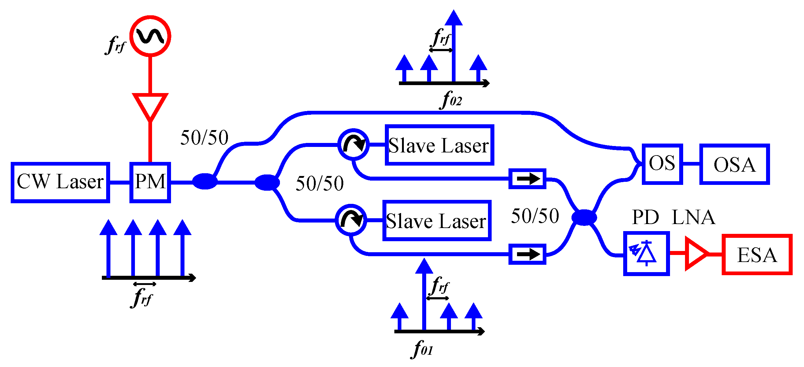
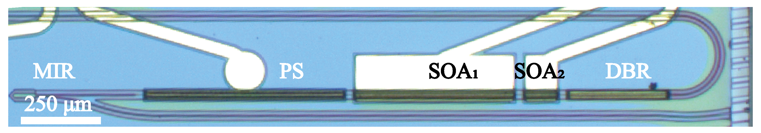
3. Materials and Methods—Experimental Setups and Employed Lasers

Figure 2 shows the experimental setup used to demonstrate sub-THz signal generation based on injection locking of a pair of lasers to different tones of an OFC. The optical signal from an external, off-the-shelf laser with a linewidth less than 100 kHz (CoBright-DX1) was modulated with an external phase modulator (PM, PM-DVES-40-PFA-PFA-LV) to generate OFC. The PM was driven with a sinusoidal signal f R F boosted by a power amplifier (ERZ-HPA-3000-4000-32-E) with an operational bandwidth of 30–40 GHz. Modified electrodes of PM are able to dissipate high RF powers up to 2 W. This configuration allows generating an OFC with a width above 300 GHz and repetition rate f R F . To monitor the OFC, a 50:50 coupler was used to direct half the signal to an optical spectrum analyzer (OSA). The remainder of the signal was split again into two parts and injected into the two on-chip slave lasers (SLs) through circulators. The frequencies of the free-running lasers were tuned to match one of the comb lines of the OFC. Subsequently, the signal from both SLs was mixed and directed in equal parts to the OSA and the photodiode (PD). The frequency of the beat note, generated on PD, is equal to the frequency difference of the two selected optical tones, and the electrical signal of PD can be expressed as
E RF P 1 P 2 cos ( ω R F t + ϕ ( t ) )
where P 1 and P 2 are the powers of the optical tones, and w R F = w 1 w 2 and ϕ ( t ) describe phase variations conditioned by frequency instabilities of the free running lasers and differences in optical path length between two channels. The signal from the PD was amplified by a low-noise amplifier (LNA) and analyzed using an electrical spectrum analyzer (ESA).
Slave lasers were represented by monolithically integrated DBR lasers (Figure 3), fabricated with standard MPW run [39]. Using MPW service significantly decreases the costs of the fabrication process due to the fact of shared costs with all participants of the run. However, on the other hand, such manufacturing imposes restrictions on the choice of components, since only building blocks represented by the platform can be used. The cavity of the laser was formed by a DBR mirror and broadband multimode interference reflector (MIR). The DBR has a uniform pitch of 236 nm, which determines a central reflection wavelength of roughly 1550 nm. The gain was provided by two semiconductor optical amplifier (SOA) sections. The wavelength was adjusted by thermally tuning cavity length by changing the feed current of the lasers and fine-tuning was carried out by reverse biasing of the phase section. The output waveguides of the lasers are bent at an angle of 7 at the chip facets to suppress reflections. A set of two chips with different types of lasers with a different length of DBR and SOA 1 were used in this study, as shown in Table 1.
During the experiment, the slave lasers were placed on a thermal control stage with a constant temperature of 20 C to avoid detuning due to temperature drifts. It is important to note that in this work, thermal tuning was the dominant mechanism of adjustment of the emitting wavelength, achieved through the change of the injected current with the thermal control stage as an effective heatsink and temperature reference plane. The light was injected into the chips with the help of lensed fibers. To simplify the analysis, the light was injected from the side of MIR [40], which is broadband compared with the DBR. This configuration ensures that all optical tones of the OFC can penetrate the cavity in a similar proportion without additional filtering. In the case of injection from the DBR side, the reflector suppresses all side tones outside of the transfer function of DBR, which makes estimation of the suppression ratio more complicated. Prior to injection, each slave laser was thermally tuned to match one of the comb lines. After injection, achieving of a stable locking state was monitored with the OSA and ESA, and fine adjustments were made by both thermal tuning and phase shifter bias tuning. Achieving a fully locked state was accompanied by a significant linewidth reduction of the beating tone, detected with the ESA as seen in Figure 4a, and as the canceling of all additional tones, observed from the point where the interaction of master seed and slave laser started and before the slave was fully locked. Another figure of merit if the laser was locked or not was frequency stability: frequency variation of the heterodyne beating of the two free-running lasers was in the range of hundreds of MHz, while after injection of the seed (and even before full locking) the frequency stabilized and followed the frequency of the RF source, which determined the spacing between tones of the optical comb. In terms of linewidth reduction, a great impact of locking is seen, allowing to reduce the linewidth below 100 kHz (Figure 4b).

4. Results and Discussion

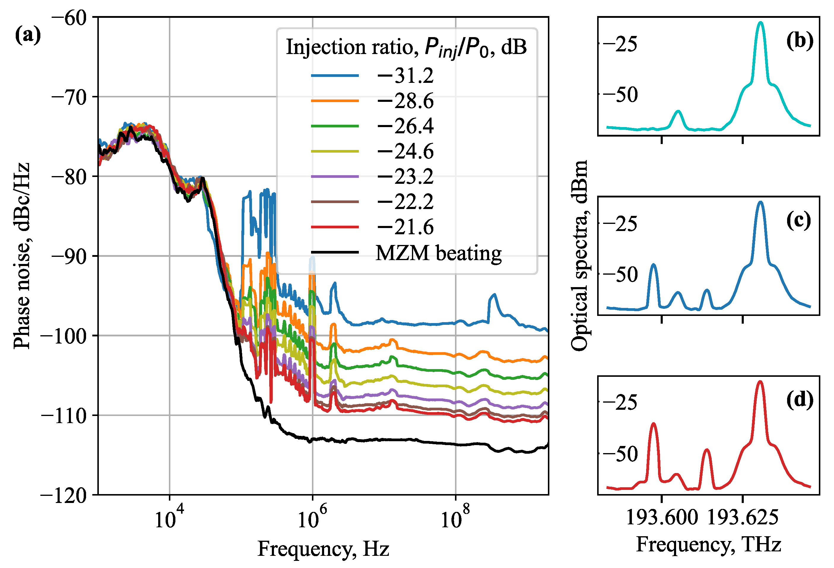
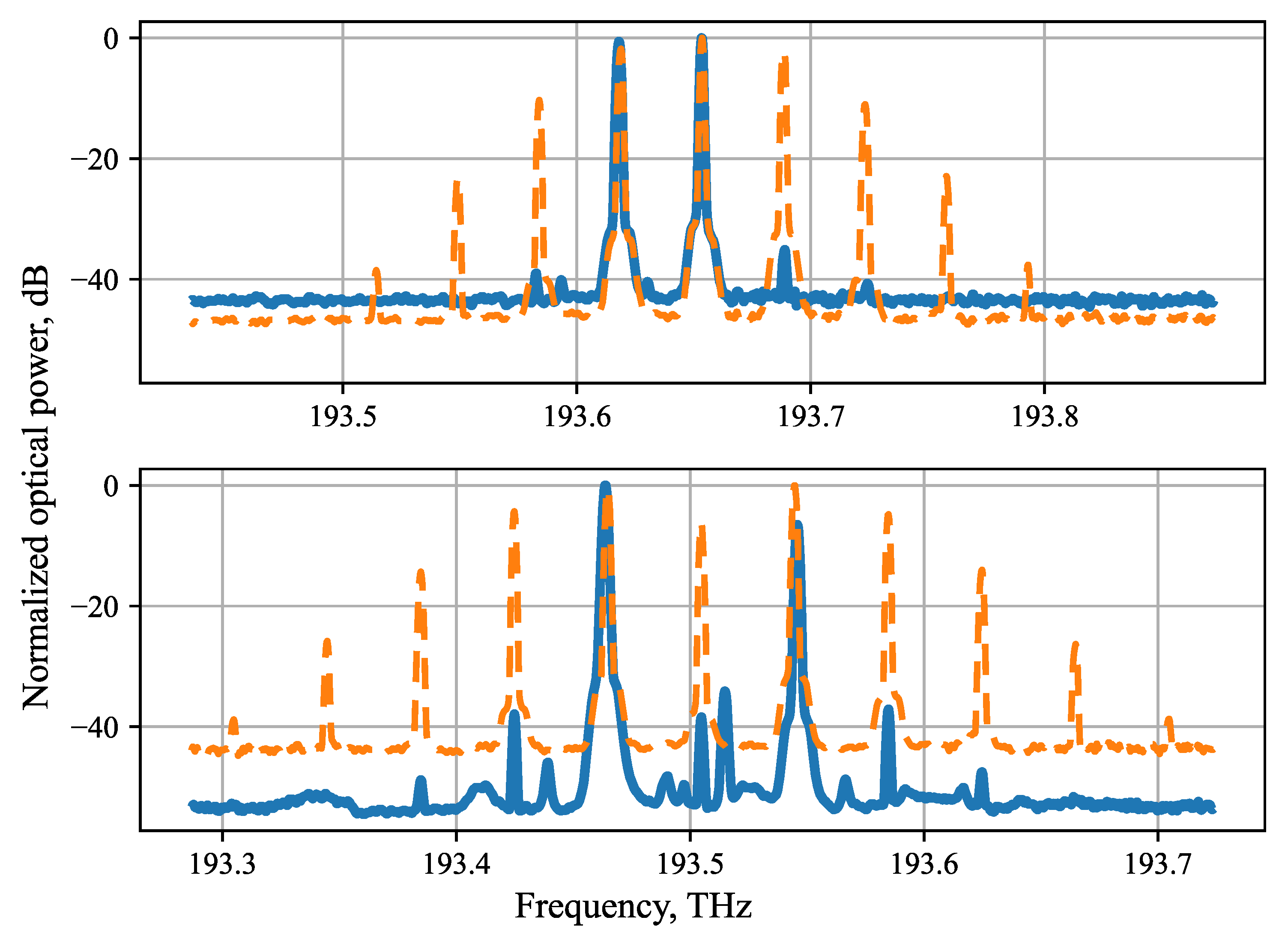
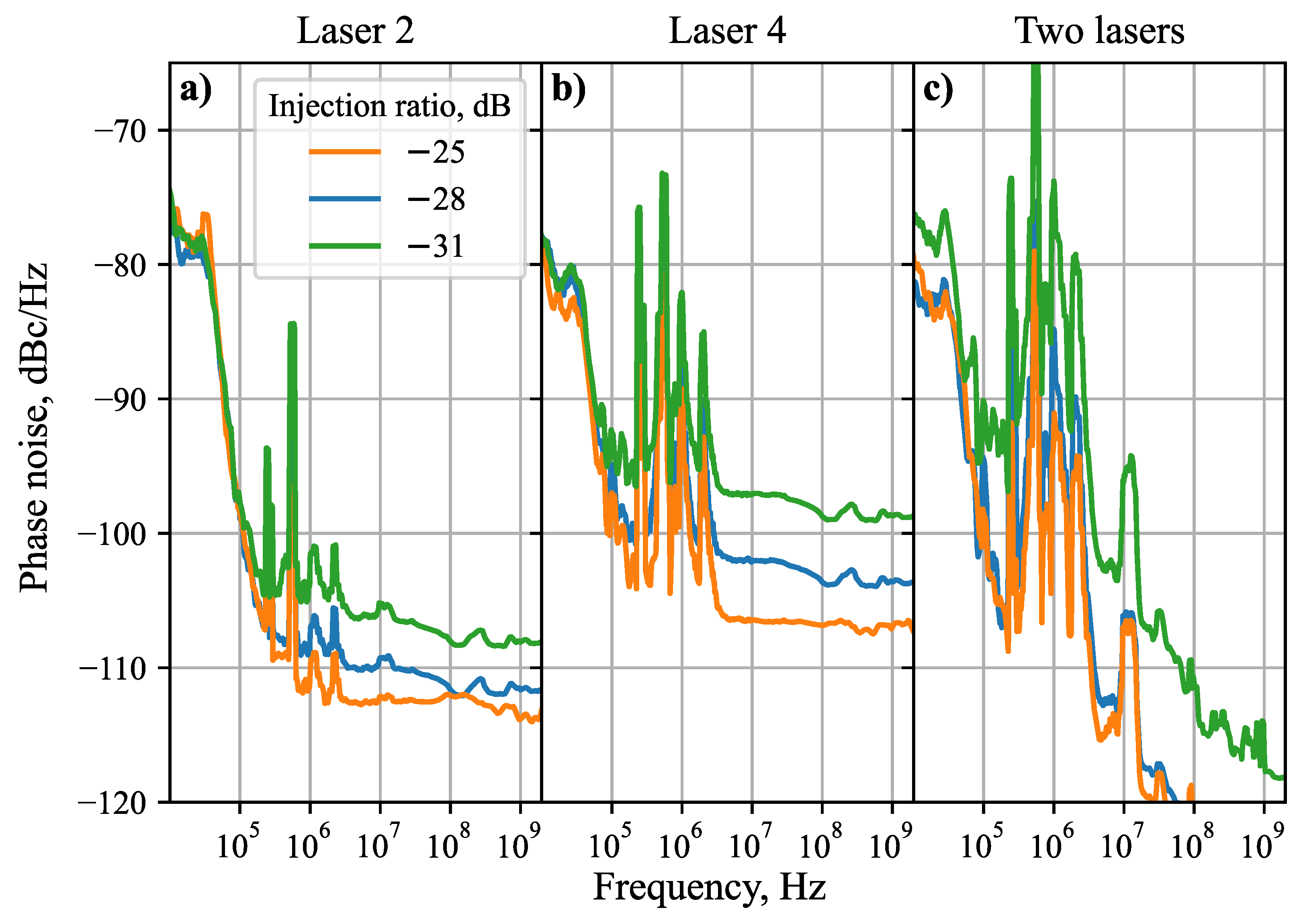
4.1. Injection Locking with a Single Laser

In order to measure the locking range of the laser, i.e., the range within which the slave laser locks to a tone of the injected comb without retuning, a modified setup as shown in Figure 5a was used. The phase modulator was replaced with a Mach–Zehnder modulator (MZM) to generate only two optical tones, and a variable optical attenuator was added to control the power of the injected light. The MZM was biased at the null point to suppress the carrier and modulated with a sinusoidal wave with a frequency of f R F in the range of 15–18 GHz, which produces two optical tones with a spacing of 30–36 GHz. This configuration produces two optical tones with spacing equal to 2 f R F . The slave laser was thermally tuned to match one of the external optical tones. The incident light was controlled through an optical coupler and achieving the locking state was monitored by analyzing the electrical signal from the photodiode and direct measurement of the optical signal. Detuning of the master signal was achieved by changing the RF frequency of the source, and injected power was tuned by means of the VOA.
Figure 5b shows the measured locking range as a function of injection ratio P i n j / P 0 , where P i n j is the power of a master signal and P 0 is the power of the slave laser, for two different currents feeding SOA 1 . As can be seen, a locking range of about 2 GHz is achieved with an injection ratio of −20 dB. The shape of the locking range is in good agreement with predictions based on analytical estimation of the locking range [24,41]:
k 1 + α 2 P i n j P 0 = w m i n < Δ w < w m a x = k P i n j P 0
where Δ w = w m a x w m i n , k is the coupling coefficient, and α is the linewidth enhancement factor.
In order to confirm that slave laser performance stays the same for different locking points within the locking range, phase noise (PN) of the output electrical signal resulting from beating the slave laser with the remaining second tone from the master on the PD can be analyzed as an indicator for locking quality, as it is related to the linewidth of the optical tone [42]. The measured PN when using Laser 1 (see Table 1) is shown in Figure 5c for different frequency offsets of the master tone and an injection ratio of −18 dB, showing that for all measured frequency offsets, the shape and level of the phase noise profile remains the same. This observation can be explained by the fact that locking is similar for any different locking point within a limited locking range.
Another important aspect of injection locking is the quality of locking for different injected powers. Minimization of the injected ratio is desirable in order to increase suppression ratio between amplified tone and residual lines of the OFC. Similarly, in complex systems, it is possible to use a single master laser to lock arrays of slave lasers, which also decreases the available power to each copy of the signal, forcing locking at small injection ratios. Figure 6a shows the variation of the PN of the locked Laser 3 due to a decrease in the optical power from the master injected into the cavity of the SL for zero offset of the master tone. For all different injected ratios, we can see identical behavior of the PN at frequency offsets up to 100 kHz. At these offsets, the PN of the beating between the locked laser and the master tone follow the PN profile of the RF signal generator with a constant offset, as expected from a frequency doubling two-tone system with suppressed carrier [43], suggesting that the slave laser accurately matches the master tone. However, starting at 100 kHz, PN behavior starts to differ from the master PN profile, and this difference increases with the decrease in the injected power. Such phenomena may be due to the fact that more power is required to ensure the SL is fully locked to the master and, consequently, PN contributions of the laser at larger offsets are also suppressed. Further, comparing Figure 5c and Figure 6a, it can be noticed that PN has a similar shape at frequencies below 100 kHz, but has a different profile at larger frequency offsets. This behavior of the PN can indicate the different performance of the lasers due to the divergent designs or fabrication variations, while at the same time, the fact that PN starts to increase at the same frequency offset can tell us that injection locking cannot suppress all fluctuations in the slave laser. Finally, it should be noted that the difference of the noise floor at higher frequency offsets was determined by different power levels of RF beat tone, resulting from reduced power from the secondary master tone.

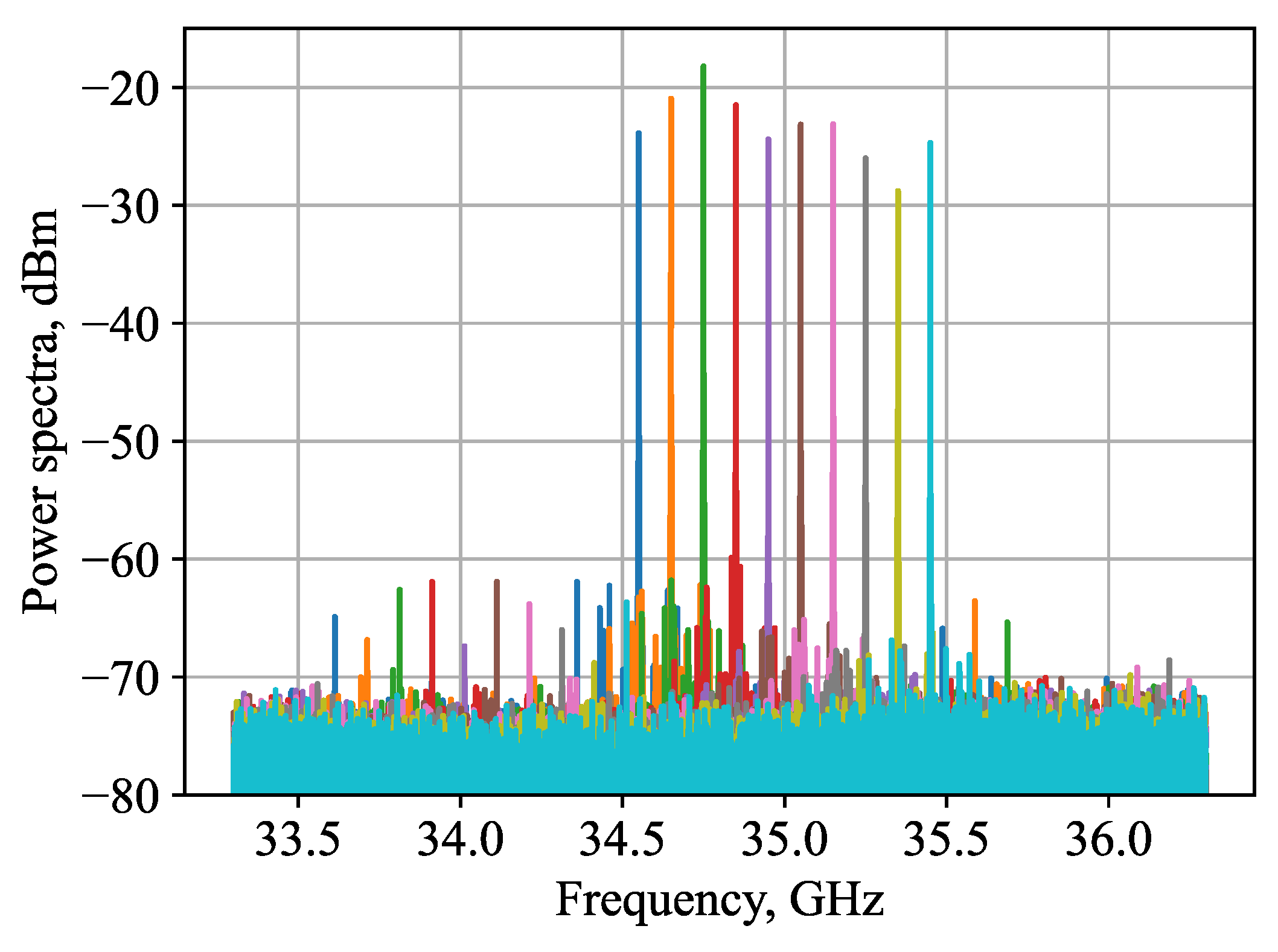
4.2. Injection Locking with Two Lasers

In this section, the usage of OIL as an active filter for selecting an optical tone from the OFC and amplifying is shown. As described in the previous section, an OFC is generated using a PM and is injected into the two slave lasers, which are tuned such that two of the comb lines correspond to the free-running frequencies of the slave lasers. Respective spectra of the comb (orange) and combined locked slave lasers (blue) are shown in Figure 7. To demonstrate the tunability of such a system, the same slave lasers are locked to different pairs of comb lines with different spacings (top and bottom of Figure 7). Robust tuning of the slave lasers was provided by thermal tuning, which was limited by the current flow into the SOA section. Fine-tuning was provided using the phase section, but was similarly limited by the breakthrough voltage of the device. “Selective amplification” of two different sets of comb lines with spacings of 34.6 and 70.0 GHz was shown. In this context, “selectivity” represents the suppression ratio (SR) between the desired amplified lines and the remaining undesired tones of the original optical comb, which was as high as 37 dB in the combined signal from the two slave lasers. “Amplification” in this case refers to a power gain of 10 dB compared with the original optical tone. In this work, the measured lasers do not have tuning contacts on the DBRs, but this can be easily changed in future designs, which may significantly expand the tuning range of the slave lasers. Another useful addition to the design of the laser can be an external heater for each cavity. Further, a pair of slave DBR or DFB lasers can be designed to initially operate at different wavelengths by introducing differences in grating pitch, which can be used for selection of the different lines from a broadband OFC.
Fine-tuning in such a system can be achieved by adjusting the RF frequency f r f of the source used for comb generation. Figure 8 depicts a tuning of the RF tone, generated with two locked SLs, during continuous changing of the OFC spacing. In this measurement, one of the SLs was locked to the central line of the optical comb and the other SL was locked to the first harmonic (as in Figure 7 top). Both SLs were fixed and the injection ratio was −27 dB. A tuning range of ∼1 GHz is observed, which is in good agreement with the locking range of the single laser itself (Figure 5b). Combined with the coarse-tuning by comb line selection, such easily realized fine adjustment provides flexible tunability thanks to the phase section within the cavity and the thermal tunability of the laser, which can be useful in both communication systems and spectroscopy applications.
Analysis of the phase noise was also performed for the beating of the two locked lasers. Figure 9 illustrates the PN of the beating of each of the lasers with the remainder of the OFC, when one of the lasers was turned off (Figure 9a,b). Figure 9c depicts the beating of the two lasers, locked to the different lines of the same comb. Significant differences in performance in terms of phase noise of the two lasers are observed. For both lasers, PN has the similar profile, which copies the PN of the master signal, for frequency offsets up to 100 kHZ, and the same PN profile was demonstrated for other lasers. However, for frequency offsets higher than 100 kHz, a significant divergence in PN level was recorded. This variance may be caused by the design and fabrication differences of different chips (see Table 1). The difference in the phase noise at high frequencies is explained by the different optical power incident on the photodiode and, as a consequence, by the different power of the analyzed RF signal. Measurement of the PN for 70 GHz spacing between selected lines of OFC shows an increase in the PN of below 100 kHz for approximately 3 dB as expected.

5. Conclusions

This work presented a detailed study of optical injection locking in combination with optical frequency comb for generation of tunable, high-quality sub-THz and THz signals for applications in communications and spectroscopy. Performance improvement in terms of frequency stability and linewidth of the single laser during injection locking was shown. The linewidth of the beating tone of two lasers was reduced from more than 100 MHz to below 100 kHz. Phase noise measurements for different injection ratios and different master tone frequency offsets were conducted. It was shown that for frequency offsets below 100 kHz, phase noise of the slave laser follows the phase noise of the master for any injected power, but for higher offsets, additional phase noise was observed. The locking range was measured for different injection ratios. Selecting two lines from the OFC by means of IL and generation of RF signals was demonstrated. Tuning mechanisms were shown for two cases: coarse-tuning by selecting different sets of optical tones from OFC; fine-tuning by changing the repetition rate between the comb lines. It was also shown that the phase noise of the resulting RF signal is a sum of the phase noise of two separate signals generated with the slave lasers. This work proves the feasibility of the concept of generating of low-noise sub-THz and THz signals by means of injection locking.

Author Contributions

G.N. and S.R. developed the system concept and designed the experiment. G.N. executed the experiment and data collection and performed the data analysis. W.Y. designed the DBR lasers. G.N., S.R., W.Y. and I.T.M. discussed the results and their interpretation. G.N and S.R. wrote the manuscript. G.N., S.R., W.Y. and I.T.M. revised and corrected the manuscript. All authors have read and agreed to the published version of the manuscript.

Funding

This work was supported by the NWO HTSM project FREEPOWER under project 17094.

Institutional Review Board Statement

Not applicable

Informed Consent Statement

Not applicable

Data Availability Statement

The datasets used and/or analysed during the current study are available from the corresponding author on reasonable request.

Conflicts of Interest

The authors declare no conflict of interest.

References

  1. El Haddad, J.; Bousquet, B.; Canioni, L.; Mounaix, P. Review in terahertz spectral analysis. TrAC Trends Anal. Chem. 2013, 44, 98–105. [Google Scholar] [CrossRef] [Green Version]
  2. Neu, J.; Schmuttenmaer, C.A. Tutorial: An introduction to terahertz time domain spectroscopy (THz-TDS). J. Appl. Phys. 2018, 124, 231101. [Google Scholar] [CrossRef] [Green Version]
  3. Cisco, U. Cisco Annual Internet report (2018–2023) White Paper. 2020. Available online: https://www.cisco.com/c/en/us/solutions/collateral/executive-perspectives/annual-internet-report/whitepaper-c11-741490.html (accessed on 26 March 2021).
  4. Nagatsuma, T.; Ducournau, G.; Renaud, C.C. Advances in terahertz communications accelerated by photonics. Nat. Photonics 2016, 10, 371–379. [Google Scholar] [CrossRef]
  5. Sengupta, K.; Nagatsuma, T.; Mittleman, D.M. Terahertz integrated electronic and hybrid electronic–photonic systems. Nat. Electron. 2018, 1, 622–635. [Google Scholar] [CrossRef]
  6. Mehdi, I.; Siles, J.V.; Lee, C.; Schlecht, E. THz diode technology: Status, prospects, and applications. Proc. IEEE 2017, 105, 990–1007. [Google Scholar] [CrossRef]
  7. Hou, D.; Chen, J.; Yan, P.; Hong, W. A 270 GHz× 9 multiplier chain MMIC with on-chip dielectric-resonator antenna. IEEE Trans. Terahertz Sci. Technol. 2018, 8, 224–230. [Google Scholar] [CrossRef]
  8. Siles, J.V.; Cooper, K.B.; Lee, C.; Lin, R.H.; Chattopadhyay, G.; Mehdi, I. A new generation of room-temperature frequency-multiplied sources with up to 10× higher output power in the 160-GHz–1.6-THz range. IEEE Trans. Terahertz Sci. Technol. 2018, 8, 596–604. [Google Scholar] [CrossRef]
  9. Preu, S.; Döhler, G.; Malzer, S.; Wang, L.; Gossard, A. Tunable, continuous-wave terahertz photomixer sources and applications. J. Appl. Phys. 2011, 109, 4. [Google Scholar] [CrossRef] [Green Version]
  10. Harter, T.; Ummethala, S.; Blaicher, M.; Muehlbrandt, S.; Wolf, S.; Weber, M.; Adib, M.M.H.; Kemal, J.N.; Merboldt, M.; Boes, F.; et al. Wireless THz link with optoelectronic transmitter and receiver. Optica 2019, 6, 1063–1070. [Google Scholar] [CrossRef]
  11. Shams, H.; Fice, M.J.; Balakier, K.; Renaud, C.C.; van Dijk, F.; Seeds, A.J. Photonic generation for multichannel THz wireless communication. Opt. Express 2014, 22, 23465–23472. [Google Scholar] [CrossRef]
  12. Koenig, S.; Lopez-Diaz, D.; Antes, J.; Boes, F.; Henneberger, R.; Leuther, A.; Tessmann, A.; Schmogrow, R.; Hillerkuss, D.; Palmer, R.; et al. Wireless sub-THz communication system with high data rate. Nat. Photonics 2013, 7, 977–981. [Google Scholar] [CrossRef]
  13. Yang, S.H.; Watts, R.; Li, X.; Wang, N.; Cojocaru, V.; O’Gorman, J.; Barry, L.; Jarrahi, M. Tunable terahertz wave generation through a bimodal laser diode and plasmonic photomixer. Opt. Express 2015, 23, 31206–31215. [Google Scholar] [CrossRef] [PubMed]
  14. Berry, C.W.; Wang, N.; Hashemi, M.R.; Unlu, M.; Jarrahi, M. Significant performance enhancement in photoconductive terahertz optoelectronics by incorporating plasmonic contact electrodes. Nat. Commun. 2013, 4, 1–10. [Google Scholar] [CrossRef] [Green Version]
  15. Mittleman, D. Sensing with Terahertz Radiation; Springer: Berlin/Heidelberg, Germany, 2013; Volume 85. [Google Scholar]
  16. Williams, B.S. Terahertz quantum-cascade lasers. Nat. Photonics 2007, 1, 517–525. [Google Scholar] [CrossRef] [Green Version]
  17. Hübers, H.W.; Eichholz, R.; Pavlov, S.; Richter, H. High resolution terahertz spectroscopy with quantum cascade lasers. J. Infrared Millim. Terahertz Waves 2013, 34, 325–341. [Google Scholar] [CrossRef]
  18. Ferrero, V.; Camatel, S. Optical phase locking techniques: An overview and a novel method based on single side sub-carrier modulation. Opt. Express 2008, 16, 818–828. [Google Scholar] [CrossRef] [Green Version]
  19. Balakier, K.; Ponnampalam, L.; Fice, M.J.; Renaud, C.C.; Seeds, A.J. Integrated semiconductor laser optical phase lock loops. IEEE J. Sel. Top. Quantum Electron. 2017, 24, 1–12. [Google Scholar] [CrossRef] [Green Version]
  20. Morales, A.; Nazarikov, G.; Rommel, S.; Okonkwo, C.; Tafur-Monroy, I. Highly Tunable Heterodyne Sub-THz Wireless Link Entirely Based on Optoelectronics. IEEE Trans. Terahertz Sci. Technol. 2021, 11, 261–268. [Google Scholar] [CrossRef]
  21. Balakier, K.; Fice, M.J.; van Dijk, F.; Kervella, G.; Carpintero, G.; Seeds, A.J.; Renaud, C.C. Optical injection locking of monolithically integrated photonic source for generation of high purity signals above 100 GHz. Opt. Express 2014, 22, 29404–29412. [Google Scholar] [CrossRef]
  22. Carpintero, G.; Hisatake, S.; de Felipe, D.; Guzman, R.; Nagatsuma, T.; Keil, N. Wireless data transmission at terahertz carrier waves generated from a hybrid InP-polymer dual tunable DBR laser photonic integrated circuit. Sci. Rep. 2018, 8, 1–7. [Google Scholar] [CrossRef]
  23. Siegman, A. Lasers; University Science Books: Sausalito, CA, USA, 1986. [Google Scholar]
  24. Liu, Z.; Slavík, R. Optical injection locking: From principle to applications. J. Light. Technol. 2019, 38, 43–59. [Google Scholar] [CrossRef]
  25. Albores-Mejia, A.; Kaneko, T.; Banno, E.; Uesaka, K.; Shoji, H.; Kuwatsuka, H. Optical-comb-line selection from a low-power/low-OSNR comb using a low-coherence semiconductor laser for flexible ultra-dense short range transceivers. In Proceedings of the Optical Fiber Communication Conference, Los Angeles, CA, USA, 22–26 March 2015; p. W2A.23. [Google Scholar]
  26. Liu, Z.; Farwell, S.; Wale, M.; Richardson, D.J.; Slavík, R. InP-based optical comb-locked tunable transmitter. In Proceedings of the Optical Fiber Communication Conference, Anaheim, CA, USA, 20–22 March 2016; p. Tu2K.2. [Google Scholar]
  27. Kasai, K.; Wang, Y.; Beppu, S.; Yoshida, M.; Nakazawa, M. 80 Gbit/s, 256 QAM coherent transmission over 150 km with an injection-locked homodyne receiver. Opt. Express 2015, 23, 29174–29183. [Google Scholar] [CrossRef]
  28. Zhou, R.; Shao, T.; Pascual, M.D.G.; Smyth, F.; Barry, L.P. Injection locked wavelength de-multiplexer for optical comb-based nyquist wdm system. IEEE Photonics Technol. Lett. 2015, 27, 2595–2598. [Google Scholar] [CrossRef]
  29. Fukushima, S.; Silva, C.; Muramoto, Y.; Seeds, A.J. Optoelectronic millimeter-wave synthesis using an optical frequency comb generator, optically injection locked lasers, and a unitraveling-carrier photodiode. J. Light. Technol. 2003, 21, 3043–3051. [Google Scholar] [CrossRef] [Green Version]
  30. Ng’oma, A.; Fortusini, D.; Parekh, D.; Yang, W.; Sauer, M.; Benjamin, S.; Hofmann, W.; Amann, M.C.; Chang-Hasnain, C.J. Performance of a multi-Gb/s 60 GHz radio over fiber system employing a directly modulated optically injection-locked VCSEL. J. Light. Technol. 2010, 28, 2436–2444. [Google Scholar] [CrossRef]
  31. Suelzer, J.S.; Simpson, T.B.; Devgan, P.; Usechak, N.G. Tunable, low-phase-noise microwave signals from an optically injected semiconductor laser with opto-electronic feedback. Opt. Lett. 2017, 42, 3181–3184. [Google Scholar] [CrossRef]
  32. Shortiss, K.; Dernaika, M.; Shayesteh, M.; Peters, F.H. The effect of relaxation oscillations in integrated optical comb demultiplexers based on injection locking. IEEE J. Quantum Electron. 2019, 55, 1–6. [Google Scholar] [CrossRef]
  33. Bordonalli, A.C.; Fice, M.J.; Seeds, A.J. Optical injection locking to optical frequency combs for superchannel coherent detection. Opt. Express 2015, 23, 1547–1557. [Google Scholar] [CrossRef]
  34. Yao, J. Microwave photonics. J. Light. Technol. 2009, 27, 314–335. [Google Scholar] [CrossRef]
  35. Fortier, T.; Baumann, E. 20 years of developments in optical frequency comb technology and applications. Commun. Phys. 2019, 2, 1–16. [Google Scholar] [CrossRef]
  36. He, C.; Pan, S.; Guo, R.; Zhao, Y.; Pan, M. Ultraflat optical frequency comb generated based on cascaded polarization modulators. Opt. Lett. 2012, 37, 3834–3836. [Google Scholar] [CrossRef]
  37. Dou, Y.; Zhang, H.; Yao, M. Generation of flat optical-frequency comb using cascaded intensity and phase modulators. IEEE Photonics Technol. Lett. 2012, 24, 727–729. [Google Scholar] [CrossRef]
  38. Headland, D.; Monnai, Y.; Abbott, D.; Fumeaux, C.; Withayachumnankul, W. Tutorial: Terahertz beamforming, from concepts to realizations. Apl Photonics 2018, 3, 051101. [Google Scholar] [CrossRef] [Green Version]
  39. Smit, M.; Leijtens, X.; Ambrosius, H.; Bente, E.; Van der Tol, J.; Smalbrugge, B.; De Vries, T.; Geluk, E.J.; Bolk, J.; Van Veldhoven, R.; et al. An introduction to InP-based generic integration technology. Semicond. Sci. Technol. 2014, 29, 083001. [Google Scholar] [CrossRef]
  40. Kleijn, E.; Smit, M.K.; Leijtens, X.J. Multimode interference reflectors: A new class of components for photonic integrated circuits. J. Light. Technol. 2013, 31, 3055–3063. [Google Scholar] [CrossRef] [Green Version]
  41. Lau, E.K.; Wong, L.J.; Wu, M.C. Enhanced modulation characteristics of optical injection-locked lasers: A tutorial. IEEE J. Sel. Top. Quantum Electron. 2009, 15, 618–633. [Google Scholar] [CrossRef]
  42. Tkach, R.; Chraplyvy, A. Phase noise and linewidth in an InGaAsP DFB laser. J. Light. Technol. 1986, 4, 1711–1716. [Google Scholar] [CrossRef]
  43. Rommel, S.; Dodane, D.; Grivas, E.; Cimoli, B.; Bourderionnet, J.; Feugnet, G.; Morales, A.; Pikasis, E.; Roeloffzen, C.; van Dijk, P.; et al. Towards a scaleable 5G fronthaul: Analog radio-over-fiber and space division multiplexing. J. Light. Technol. 2020, 38, 5412–5422. [Google Scholar] [CrossRef]
Figure 1. General schematic of using a combination of optical frequency comb and injection locking for generation of THz wave. SA—“selective amplification”; SP—signal processing; PCA—photoconductive antenna.
Applsci 11 10185 g001
Figure 2. Experimental setup for sub-THz signal generation based on injection locking of a pair of InP DBR lasers to different lines of an optical comb. PM—phase modulator; OS—optical switch; OSA—optical spectrum analyzer; PD—photodiode; LNA—low-noise amplifier; ESA—electrical spectrum analyzer.
Applsci 11 10185 g002
Figure 3. Microscope photograph of a section of the chips, showing one of the used lasers and identifying the relevant on-chip laser components. MIR—multimode interference reflector; PS—phase shifter; SOA—semiconductor optical amplifier; DBR—distributed Bragg reflector.
Applsci 11 10185 g003
Figure 4. Electrical spectra for (a) comparison of two free-running lasers and two locked lasers and (b) linewidth estimation of two locked lasers.
Applsci 11 10185 g004
Figure 5. (a) Experimental setup for measuring the locking characteristics of a single laser; (b) measured (dots) and theoretical (solid) locking range of a single laser for two different feeding currents; (c) phase noise power spectral density of the RF tone resulting from heterodyning of the injection-locked slave laser with the second master tone for different master laser frequency offsets.
Applsci 11 10185 g005
Figure 6. (a) Phase noise for different injection ratios. Optical spectra of free-running laser (b), and of locked laser with injection ratios of −31 dB (c) and −21 dB (d).
Applsci 11 10185 g006
Figure 7. Normalized optical spectra of frequency comb (orange) and locked slave lasers (blue) for two different spacings: (top) 34.6 GHz and (bottom) 70.0 GHz. Note: the apparent difference in noise floors results from the normalization of the spectra and is the shifted noise floor of the OSA rather than actual noise in the signal.
Applsci 11 10185 g007
Figure 8. Fine-tuning of the RF tone generated with two locked SLs.
Applsci 11 10185 g008
Figure 9. Phase noise of two locked lasers before (a,b) and after combining (c).
Applsci 11 10185 g009
Table 1. Parameters of the InP DBR lasers employed as slave lasers.
LaserDBR, ( μ m)SOA 1 , ( μ m)SOA 2 , ( μ m)PS, ( μ m)Chip
Laser 13505001005001
Laser 22505001005001
Laser 32505001005002
Laser 42504001005002
Publisher’s Note: MDPI stays neutral with regard to jurisdictional claims in published maps and institutional affiliations.

