1. Introduction
Recently, industries in major countries have shifted from a labor-intensive production structure to a knowledge-intensive structure. As a result, competition for product performance and quality is intensifying. Korean manufacturing industries, such as semiconductors, automobiles, and mobiles, use standardized communication technologies to respond immediately to customer changes and prepare measures for mass production of various types [
1]. In this environment, Industry 4.0 is a paradigm that has evolved into a smart factory or an intelligent factory in the traditional manufacturing industry [
2].
The complexity of a smart factory has increased significantly due to changes in the market according to the various needs of consumers, development of cyber-physical systems (CPS), Internet of things (IoT), wireless communication technologies, and so on [
3].
Recently, services such as communication, banking, and shopping provided by companies have also been fused with information and communication technology. They can be performed without interactions between individuals. In addition, as heterogeneous computing devices, software, and communication methods are very closely coupled, computing technologies are evolving into complex, diverse, and large-scale systems that interwork with each other in a distributed environment and achieve a common purpose or goal.
When various manufacturing facilities, such as smart factories that communicate with each other and form a network to perform various processes, are operated, there is a very high possibility of more error situations than before. The complexity of the system is very high due to the connection between manufacturing facilities that perform various manufacturing processes and the communication network. Accordingly, the possibility of unexpected errors or situations also increases [
4].
In particular, the implementation of smart factories is being promoted by the development of cyber-physical systems and IoT technologies, which are complex aggregates of information and communication technologies. For more reliable implementation, communication middleware/protocol, autonomous computing technology, and manufacturing simulation or facility, research in various fields, such as a data platform that can secure interoperability, is essential. In other words, a methodology that guarantees a smart factory environment known to require high reliability is absolutely necessary. Reliability in the smart factory field cannot be guaranteed only by combining embedded systems developed by traditional methods. It is essential to develop technology for solving problems that occur during operation [
5,
6].
1.1. Contribution
Semantic-based autonomous computing technologies for high-reliability smart factories can be explained by securing communication middleware/protocol, autonomous computing technology, and interoperability to advance smart factory. If semantic-based autonomous computing technologies are applied to the smart factory field, they can manage themselves during operation. If necessary, the smart factory can reconfigure and update manufacturing facilities on its own to perform reliable manufacturing processes.
1.2. Paper Organization
The structure of this paper is as follows. In
Section 2, communication middleware technology trends for smart factories are discussed and MTConnect technology is explained.
Section 3 describes the technological trend of traditional autonomic computing and explains the proposed error tree and goal model.
Section 4 describes the structure tailored to the Semantic Web and smart factory.
Section 5 describes the design of the semantic-based autonomic computing technology proposed in this paper.
Section 6 presents conclusions and the scope of future research.
2. Communication Middleware Technology Trend for Smart Factory
The evolution of the computer environment has made it possible to link various manufacturing facilities in the manufacturing process. As a result, various types of communication methods have emerged, and various communication services are being expanded. These communication services are specialized according to the characteristics of the manufacturer. There is a problem of using a protocol dependent on the manufacturer. To solve this problem, standardized communication middleware technologies that can be applied to various industries have been developed to eliminate direct data exchange between devices and provide autonomous and efficient data communication.
The main core technology of communication middleware is data-oriented, high-reliability, real-time data distribution technology. That is, for facilities made by various manufacturers to be controlled/managed in an integrated environment, standardized industrial communication protocols are needed [
7].
The current industrial communication protocol has evolved from the existing serial communication to an Ethernet-based communication method. To unify the Ethernet communication method and increase the data interoperability between devices, various international standardization organizations are converging demands for industrial communication protocol standardization. By applying these requirements, communication middleware, such as Data Distribution Service (DDS), and communication protocols, such as OLE Process Control (OPC) and MTConnect, were standardized. This chapter describes the characteristics of DDS, OPC, and MTConnect.
2.1. DDS
DDS [
8] is a network communication middleware standard proposed by Object Management Group (OMG). It supports scalability, real-time, reliability, high performance, and mutual data exchange. A programming model related to data-centric publishers/subscribers for a distributed environment is standardized. To simplify complex network programming, DDS is a network communication middleware that implements a publisher/subscriber model that exchanges data, events, and commands between nodes (heterogeneous embedded devices). The publisher creates a topic that is the basis for generating information. It is a structure in which data samples are published. It then distributes the data sample to all the subscribers interested in the topic.
DDS manages message addressing, data marshaling, demarshalling, distribution, flow control, and retries. In addition, DDS has the characteristics of a message-based connectionless service. It provides a real-time communication environment that enables access to data regardless of service information (location, time, synchronization).
2.2. OPC
OPC [
9] is an industrial communication protocol standard to securely and reliably exchange data in the automation field of manufacturing. OPC was standardized to improve problems existing in the manufacturer-dependent monitoring system. Control SW/HW, Microsoft’s OLE (Object Linking and Embedding), COM/DCOM (Component Object Model/Distributed Component) Object Model), the server, and client exchanging data have to comply with standardized matters. OPC is divided into ‘OPC Data Access’ for OPC data access, ‘OPC Alarms and Events’ for OPC alarms and events, and ‘OPC Historical Data Access’ for OPC historical data access. However, OPC is dependent on Microsoft’s OLE and COM/DCOM technologies. Therefore, a new standard, OPC-UA (OLE for Process Control Unified Architecture), has been recently proposed to compensate for these shortcomings of OPC [
10]. OPC-UA is an integrated open platform that supports security (mutual authentication, encryption) and data modeling.
2.3. The Need for MTConnect
As mentioned above, communication middleware/protocols, such as DDS, OPC, and OPC-UA, are being developed for mutual data exchange between heterogeneous devices. However, for interactions with heterogeneous devices and systems, a higher level of interoperability is required with a simple data exchange/conversion.
Recently, the industrial network environment has been evolving from a closed structure to a service-oriented structure from the point of view of information technology. Data distributed in a closed way inside the factory are open to the outside for company-wide visibility. In other words, the need for interoperability is increasing. MTConnect is an industrial communication protocol standard based on communication/analysis using ‘agent/API’ and so on. MTConnect is a standard based on XML message format and RESTful interface [
11].
2.4. MTConnect
MTConnect [
12] is an extensible lightweight protocol developed for the data exchange between manufacturing facilities and applications. It is mainly used for monitoring and data analysis in industrial network environments.
MTConnect parses and provides manufacturing facility data in XML format (based on HTTP protocol). The interoperability can be greatly improved by exchanging data between different types. In addition, by using the RESTful interface method, the scale scalability and versatility of the interaction can be increased.
There are three data types that can be expressed by MTConnect: (1) property data of a physical device (model number, serial number, maximum speed, device threshold, and so on); (2) real-time data measured by the device; and (3) real-time data of the device itself (current speed, position, temperature, and so on).
The MTConnect structure consists of eight basic elements, as shown in
Table 1 below.
In MTConnect, there is an ‘agent’ that performs the role of real protocol implementation and XML generation. This ‘agent’ stores and manages data in the form of ‘key/value’ through a queue. As shown in
Figure 1, the agent can manage using unique keys.
MTConnect’s agent processes XML messages in a FIFO method. To identify the data stored in the queue, there are three request types, as shown in
Table 2.
Table 3 shows MTConnect’s response XML main elements of messages.
Recently, methodologies for the high reliability of MTConnect based cyber physical systems (CPS) have been developed. They are being used in domains such as manufacturing, defense, and aviation. In particular, the MTConnect Association and OPC Council are promoting MTConnect and OPC-UA Companion standards to ensure the interoperability between the standards maintained by each organization and to expand the scope of the existing manufacturing data exchange standards and implementation technologies. In addition to UA, the use of MTConnect is expected to expand further.
3. Traditional Autonomous Computing Technology Trends
Traditional autonomous computing technologies consider the following requirements to secure reliability, robustness, and availability.
Monitoring: to identify ‘errors’ in the running system.
Analysis: to analyze types of identified errors and determine the problem resolution request by analyzing the severity of the problem.
Diagnosis: to diagnose the cause of the problem and suggest a solution based on the diagnosis.
Strategies: to choose strategies to solve problems that have arisen.
Implementation: to dynamically deploy and execute the structure and behavior of the target management system in operation.
Based on the above-mentioned requirements, an autonomic computing technology should be able to control and resolve errors that occur in the system automatically/autonomously. Such technology can recover system errors by self-managing the state of the system while minimizing human interference [
14].
The traditional component-based autonomous control methodology [
15] uses an autonomous control method for error detection in a component-based system consisting of components and connectors. For autonomous control, it has a feature of detecting errors that have occurred by setting a component monitor inside the component. The component monitor can monitor objects inside the component and the message-passing relationship between the components. It can execute the strategy of reconstructing the component relationship when the constraint is violated by comparing the state information prepared in advance in the state chart. This methodology has advantages of stipulating the message delivery relationship of the facilities operating in a manufacturing environment and handling errors that occur.
However, it is necessary to analyze errors that occur in the manufacturing facilities, communication protocols, and server-side since a lot of manpower and time are required to analyze the manufacturing process for various purposes. One of various ways to solve this problem is to design a management area that can understand the manufacturing environment, that is, a ‘target model’ and an ‘error model’.
The heartbeat framework [
16] proposes a method for checking the communication signal based on the component’s communication environment and recognizing the normal/abnormal status of the management component. This methodology has the advantage of checking the normal operation of components based on a timer and a heartbeat generator. A non-response of the communication signal indicates that an error has occurred inside the system. If there is no response to the heartbeat signal, a reset and restart strategy can be used to solve the problem. As an advantage, it is easy to detect the normal/abnormal conditions of a component or system by testing the response time for a communication signal. In addition, the consumption of system resources for autonomous control is reduced. However, it is very difficult to identify the type of error related to the internal state of a component. One of many ways to solve this problem is to reflect ‘error modeling’.
An error event-based autonomous control methodology [
17] has the characteristic of emphasizing the importance of error analysis by constructing a chain that can infer errors and symptoms. This methodology has the advantage of providing the data required for autonomous control by analyzing the normal operation of a target system to be managed. It then extracts and defines possible errors. However, such a methodology can lead to inaccurate definitions of errors for abnormal phenomena. Therefore, it is necessary to clearly define the error event that meets the management goal.
Our previous study proposed an autonomous control methodology for a highly reliable cyber-physical system [
18]. It is a method for building a knowledge base to construct autonomous control systems. This methodology creates a knowledge base, such as error analysis, error event definition, error modeling, error state analysis, and strategy decision. As an advantage, the detailed creation process of the knowledge base is well explained. However, it is necessary to analyze the error associated with the target model that models the management goal. In other words, more advanced autonomous control methodologies need to be implemented. Although traditional autonomous control research has been conducted at home and abroad, research in the smart factory field is still in its early stage.
Thus, the aim of this study was to present a target model methodology and an error tree-based control methodology for building a high-reliability smart factory.
Autonomous Control Process
Figure 2 shows the autonomous control process by linking the target model and the error tree. It enables autonomous control in a four-step process: (1) mapping target model constraints, (2) monitoring target achievement rates, (3) recognizing problems and requesting diagnosis, and (4) diagnosing problems and executing strategies [
19].
(1) To evaluate the error of a system, a constraint (a criterion for evaluating whether the goal is violated) must be connected to the goal, as shown in
Figure 3. At this stage, it becomes a basic model of goal achievement by linking the constraints to the goals of the abstract system.
(2) Through the goal model to which constraints are mapped, the overall goal achievement rate of the system is monitored. If the target achievement rate is lower than expected, it recognizes that a problem has occurred and executes the next step, problem recognition and diagnosis request.
(3) At the current stage, if the goal achievement rate is violated, the current state is diagnosed and the cause is inferred based on the error tree shown in
Figure 4 to recognize the goal that has not been achieved.
Table 4 shows an error table prepared.
(4) The error table determines the appropriate strategy from the strategy execution table and executes the strategy.
Table 5 shows the strategy execution table.
4. Semantic Web
Semantic web technology was proposed in 1998 by Tim Berners-Lee, the founder of the Web. A semantic web means a web with meaning. In more detail, it is a technology that expresses each resource object in a Linked List relationship on the Internet in a form that a machine or computer can understand and process. Through the application of these semantic technologies, the web can deliver simple information to a framework so that various services can be provided based on meaning [
20].
4.1. Design of Semantic Factory
To build a semantic smart factory, it is necessary to analyze the components within the factory. The components of a traditional factory were man, material, method, and machine (4M). Today, these components have evolved into man, material, method, machine, and environment (4M1E), which includes factors such as pollution reduction.
Man can be defined as a worker. Its attributes may include general attributes, such as affiliation, position, years of service, disability, and attitude of the worker. Material indicates the material required for production. It includes the manufacturer, storage location, mixing ratio, and number of days in stock. Method refers to methods, mixing ratios, and order. Machine includes the equipment identification number, use, affiliated process, repair history, maintenance manual, and so on that might correspond to this.
Such information can be expressed according to the six-fold principle (5W1H). When (time stamp), where (machine), who (man), what (product or sub-product), why (work order), and why (work order) can be explained (method). That is, it can be called a situation. Manual information can be obtained accordingly.
Several methods have been proposed for the methodology for semantic design, including a method that divides the entire factory into layers of the bottom-up method and utilizes the information exchange method accordingly. The other method creates a basic ontology by analyzing the requirements through the collaboration of workers, ontology experts, and factory operation experts. It then gradually develops the ontology accordingly. There is also a technique for expanding based on information acquired, such as the facility and the asset of the facility [
21,
22,
23].
In this paper, we intended to design a semantic web based on the process. The following figure shows the semantic design based on the process presented in this paper.
As shown in
Figure 5, the process is located at the top, while facilities, workers, and materials are located at the bottom. Equipment, workers, and materials each have detailed information as subordinates, including asset details and detailed data for status values and sub-assemblies. If this is schematized in semantics, it can be expressed as the following figure.
As shown in
Figure 6, a process has relationships with workers, materials, and equipment. Workers, materials, and equipment also have relationships with each other. In other words, it is easy to understand that each object has an organic relationship within the same process.
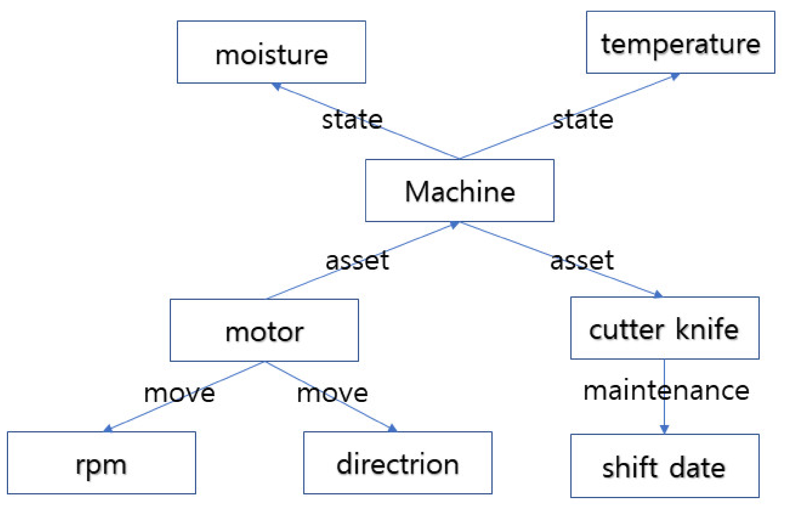
Method and environment are associated with the sub-processes of workers, materials, and equipment. In the case of the temperature and humidity of a work facility or a material storage place, their effects on workers, materials, and equipment are sub-data that can be semantized. The following figure briefly shows the sub-semantic relationships for machine.
As shown in
Figure 7, the facility has the humidity and temperature as information of the external environment. It has a relationship with the parts included in the lower level. Examples of equipment such as CNC include motors and cutting tools. It has a structure that can describe the state of each lower part in detail.
In this way, each object in the factory is configured in an organic relationship. If there is a new requirement, a semantic model is added according to it. The configuration can be expanded from a small process area to the entire factory.
4.2. Semantic Data
Semantic data are data in XML format with the structure of subject–predicate–object. They are mainly defined by defined structure words, such as RDF and OWL. RDF provides a way to describe information about the data. A widely used relational database uses a table structure to describe information about the data. However, linked of data (LOD) pursued by the Semantic Web is based on a standard called RDF to describe information about the data. This is suitable for describing Unified Resource Identification (URI) in a graph form.
Table 6 shows an example of RDF [
16].
As shown in
Figure 8, there is a rolling process in a virtual factory. The subject–predicate–object can be expressed at each step by giving a URI that can identify the worker.
OWL is a language designed to implement applications that can directly process information content. It does not just display information. As OWL includes a rich vocabulary and formal semantics, it is possible to create machine-interpretable web contents [
17].
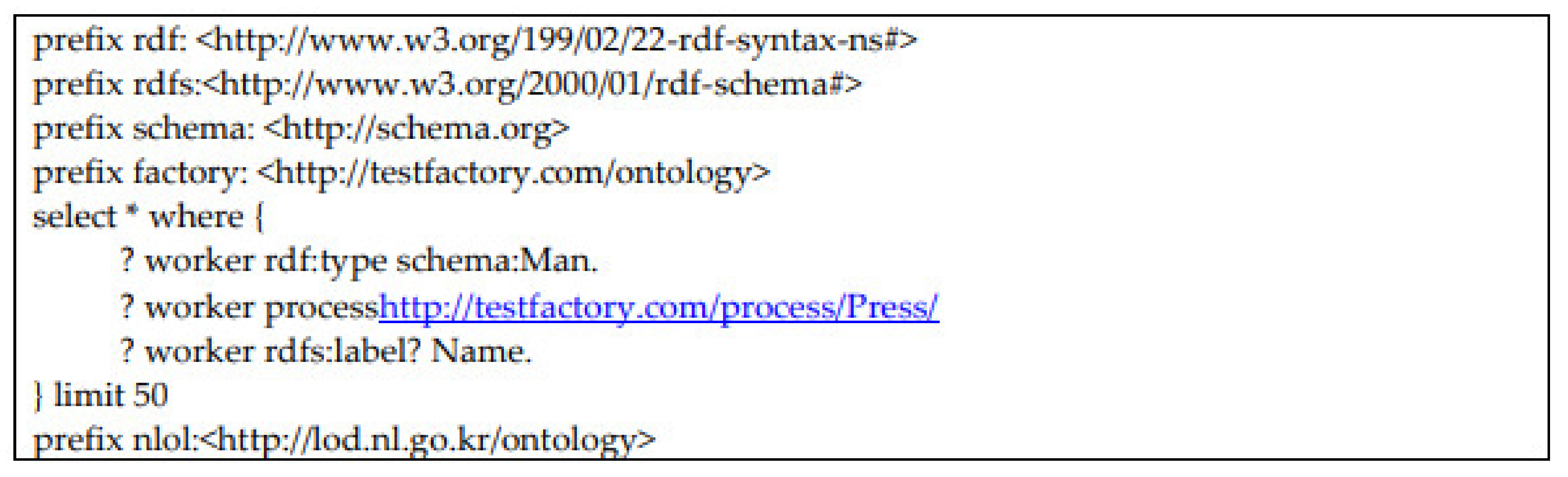
SPARQL is W3C’s standard query language for data constructed in LOD format. It has a form similar to SQL for retrieving the desired data from a relational database [
18].
As shown in
Figure 9, the desired information is retrieved using SPARQL, a language similar to SQL but with a different syntax.
5. Design of Semantic-Based Autonomous Computing Technology
The structure of the semantic-based autonomous control system proposed in this paper is designed for the predictive maintenance of smart factories. The flow of this system is shown in
Figure 10.
The flow chart of the architecture proposed in this paper is shown in the figure below. The overall structure consists of four areas. The monitoring area collects various data generated from equipment, IoT, and sensors using MTConnect adapter/agent. The collected information is serialized in XML format in accordance with the semantic standard. Through this, a monitoring server is built. In the analysis area, various situations that can occur in the semantic factory are defined in semantic language in advance. The weights for these are defined in the target model through tools, such as decision trees. The problem is identified by analyzing it in the digital twin space implemented based on the data built from a monitoring server. In the planning area, the analyzed problem is planned for preventive maintenance using expert techniques or a set manual. In the execution area, based on the strategy established in the planning area, the situation in the factory is grasped, an execution plan is established, and actual equipment, IoT, and sensors are controlled.
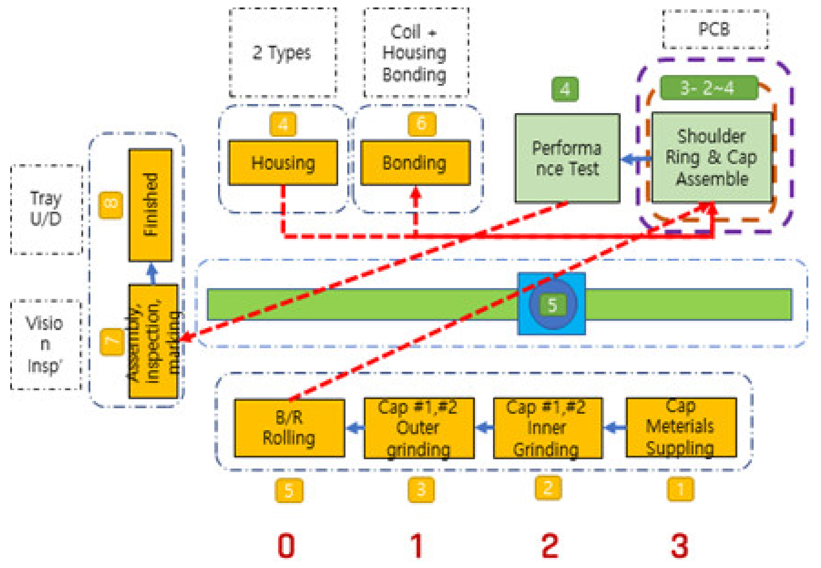
Figure 11 below is a schematic depiction of an actual motor factory in Gumi, Korea. If our proposal is applied to this factory, it can be implemented with the following model.
As shown in
Figure 11, there are five major processes: (1) a process of making a motor cap, (2) a process of making a housing, (3) a bonding process, (4) an assembly process, and (5) an inspection process. Each process is connected by an AGV equipped with a robotic arm.
When explaining the factory inner grinding equipment modeled in
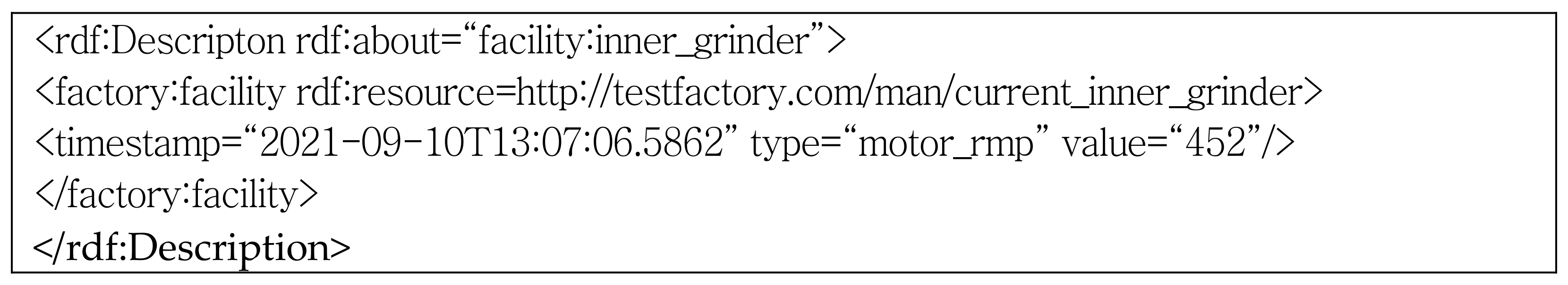
Figure 8 as an example, first, the data generated from the equipment are collected using MTConnect. The MTConnet adapter converts the binary data generated in the facility into simple hierarchical data representation (SHDR) protocol. The agent stores the received agent. If there is an http request, it converts it into XML and provides the data.
For example, if the rpm of the motor is 452 in the inner grinding process and if the SHDR of 2021-09-10T13:07:06.5862|rpm|532 occurs, <DataItem category =“EVENT”, timestamp = “2021-09-10T13:07:06.5862” id = “2000_Avail”, Type = “motor_rpm”, Value = “452”> is saved by the agent. Meanwhile, the semantic model is composed as shown in
Section 3. The data of the lower stage along the semantic hierarchy are stored as the following
Figure 12.
A digital twin is constructed based on the semantic repository transformed into semantic data. The reason why a digital twin is needed is because it consumes a lot of resources in order to perform a simulation on an actual physical model and to find and operate the optimal result value. The digital twin model defines and solves problems using goal models and expert techniques.
As shown in
Figure 13, first, a problem is found through an error tree on a digital twin that is modeled on a virtual factory, and a solution and a plan are established using the semantic repository composed of manuals and coping methods made by experts. For example, if the normal operating value of the motor is 500~800, a low rpm is a warning sign. If this is defined as an error tree, it can be expressed in the following
Figure 14.
As shown in
Figure 14, low voltage, high voltage, bearing, and vibration are defined as constraints that cause the malfunction of the motor. Certain conditions are input according to each constraint. Through this, the cause of the malfunction can be defined. The set manual and response method can be easily searched through a semantic search. By identifying the cause of an error or a danger and quickly knowing how to respond through the reference of the object in the manual linked list method, it can be used for prediction, maintenance, and accident response.
6. Conclusions
In this paper, a more intelligent smart factory construction method is considered through communication technology, autonomous control technology control, and semantic web technology for a high-trust smart factory. Traditionally, monitoring, analysis, plan, and execution (MAPE) have widely been used for autonomous control. In accordance with this methodology, necessary technologies for an intelligent smart factory are introduced.
For monitoring, new technologies, such as MTConnect, which can easily and centrally monitor data from legacy equipment, were introduced, and a method for identifying problems through traditional autonomous control methods and goal models and error analysis trees was introduced. It suggested that the analysis of errors should be carried out on the digital twin and that the problem should be solved through the semantic model built through experts and manuals. In addition, the semantic model is presented as a good data exchange method for the abstract digital twin world.
There may be other ways to utilize the semantic web, MTConnect, error tree, and goal model presented in this study through big data and AI, which have recently been in the spotlight. Although it provides a method with a high degree of freedom, considering the specificity of the factory and that most of the predictive maintenance and response to emergencies are equipped with manuals, countermeasures and the experiences of workers cannot be ignored.
In order to improve the proposal of this paper, several future tasks should be performed. The semantic model proposed in this paper should be expanded to show a more detailed semantic model. A clear framework for implementing digital twins based on real or virtual factories should be described. Moreover, based on the detailed semantic model, performance evaluations should be performed based on the suggestions in this study.
Author Contributions
Conceptualization, J.-M.P. and K.-J.K.; methodology, K.-J.K.; software, K.-J.K.; validation, J.-M.P. and K.-J.K.; formal analysis, J.-M.P.; investigation, K.-J.K.; resources, K.-J.K.; data curation, K.-J.K.; writing—original draft preparation, K.-J.K.; writing—review and editing, J.-M.P.; visualization, K.-J.K.; supervision, J.-M.P.; project administration, J.-M.P.; funding acquisition, K.-J.K. All authors have read and agreed to the published version of the manuscript.
Funding
This research was supported by a grant (2021R1F1A1063634) of the Basic Science Research Program through the National Research Foundation (NRF) funded by the Ministry of Education, Republic of Korea.
Institutional Review Board Statement
All experiments were performed in accordance with the relevant guidelines of Korea Polytechnic University.
Informed Consent Statement
All participants provided informed written consent.
Data Availability Statement
The datasets generated during this study are available from the corresponding author on reasonable request.
Conflicts of Interest
The authors declare no conflict of interest.
References
- Hyung-Uk Park. Trend of production and manufacturing technology related to smart factory. Inf. Commun. Mag. 2015, 33, 24–29. [Google Scholar]
- Jamwal, A.; Agrawal, R.; Sharma, M.; Giallanza, A. Industry 4.0 Technologies for Manufacturing Sustainability: A Systematic Review and Future Research Directions. Appl. Sci. 2021, 11, 5725. [Google Scholar] [CrossRef]
- Hozdic, E. Smart factory for industry 4.0: A review. Int. J. Mod. Manuf. Technol. 2015, 7, 28–35. [Google Scholar]
- Park, J.-M.; Lee, S.; Yoon, T.; Kim, J.M. An Autonomic control System for High-Reliable CPS. J. Clust. Comput. 2015, 18, 587–598. [Google Scholar] [CrossRef]
- Park, J.-M.; Kang, S.-J.; Jeon, I.-G.; Kim, W.-T. Network-based autonomous control CPS(Cyber-Physical Systems) technology. Inf. Commun. Mag. 2013, 30, 86–92. [Google Scholar]
- Kim, J.-R.; Lee, S.-J. Factors Affecting Technology Acceptance of Smart Factory. J. Inf. Technol. Appl. Manag. 2020, 27, 75–95. [Google Scholar]
- Ovsthus, K.; Kristensen, L.M. An industrial perspective on wireless sensor networks—A survey of requirements, protocols, and challenges. IEEE Commun. Surv. Tutor. 2014, 16, 1391–1412. [Google Scholar]
- DDS. Available online: http://portals.omg.org/dds/ (accessed on 1 March 2021).
- OPC. Available online: http://opcfoundation.org (accessed on 5 June 2021).
- OPC-UA. Available online: http://www.opcua.us/ (accessed on 5 June 2021).
- Liu, C.; Vengayil, H.; Lu, Y.; Xu, X. A cyber-physical machine tools platform using OPC UA and MTConnect. J. Manuf. Syst. 2019, 51, 61–74. [Google Scholar] [CrossRef]
- MTConnect. Available online: http://www.mtconnect.org (accessed on 5 July 2021).
- MTConnect Standard. Available online: http://mtconnect.squarespace.com (accessed on 1 March 2018).
- Lalanda, P.; McCann, J.A.; Diaconescu, A. Autonomic Computing: Principles, Design and Implementation; Springer Science & Business Media: Berlin/Heidelberg, Germany, 2013. [Google Scholar]
- Shin, M.E. Self-healing components in robust software architecture for concurrent and distributed systems. Sci. Comput. Program. 2005, 57, 27–44. [Google Scholar] [CrossRef]
- Steritt, R.; Bantz, D.F. Personal autonomic computing reflex reactions and self-healing. IEEE Trans. Syst. Man Cybern. Part C (Appl. Rev.) 2006, 36, 304–314. [Google Scholar] [CrossRef]
- Kitamura, Y.; Ueda, M.; Ikeda, M.; Kobori, S.; Kakusho, O.; Mizoguchi, R. A model-based diagnosis with fault event models. In Proceedings of the Pacific Asian Conference on Expert Systems, Singapore, 24–27 February 1997; pp. 322–329. [Google Scholar]
- Ko, D.B.; Kim, T.Y.; Park, J.M.; Kang, S.; Chun, I.G. An approach to applying goal model and fault tree for autonomic control. Contemp. Eng. Sci. 2016, 9, 843–851. [Google Scholar] [CrossRef][Green Version]
- Dias, F.F.; Nair, G.S.; Ruíz-Juri, N.; Bhat, C.R.; Mirzaei, A. Incorporating autonomous vehicles in the traditional four-step model. Transp. Res. Rec. 2020, 2674, 348–360. [Google Scholar] [CrossRef]
- Berners-Lee, T.; Hendler, J.; Lassila, O. The semantic web. Sci. Am. 2001, 284, 34–43. [Google Scholar] [CrossRef]
- Hildebrandt, C.; Köcher, A.; Küstner, C.; López-Enríquez, C.M.; Müller, A.W.; Caesar, B.; Fay, A. Ontology building for cyber–physical systems: Application in the manufacturing domain. IEEE Trans. Autom. Sci. Eng. 2020, 17, 1266–1282. [Google Scholar] [CrossRef]
- Jaleel, A.; Arshad, S.; Shoaib, M.; Awais, M. Design quality metrics to determine the suitability and cost-effect of Self- capabilities for autonomic computing systems. IEEE Access 2019, 7, 139759–139772. [Google Scholar] [CrossRef]
- Patel, P.; Ali, M.I.; Sheth, A. From raw data to smart manufacturing: AI and semantic web of things for industry 4.0. IEEE Intell. Syst. 2018, 33, 79–86. [Google Scholar] [CrossRef]
| Publisher’s Note: MDPI stays neutral with regard to jurisdictional claims in published maps and institutional affiliations. |
© 2021 by the authors. Licensee MDPI, Basel, Switzerland. This article is an open access article distributed under the terms and conditions of the Creative Commons Attribution (CC BY) license (https://creativecommons.org/licenses/by/4.0/).


