Article

Impact of the Mining Dimensions on the Stability of Backfilled Pier-Columns

1
State Key Laboratory of Coal Resources and Safe Mining, China University of Mining and Technology, Xuzhou 221116, China
2
School of Mines, China University of Mining and Technology, Xuzhou 221116, China
*
Author to whom correspondence should be addressed.
Appl. Sci. 2021, 11(20), 9640; https://doi.org/10.3390/app11209640
Submission received: 24 September 2021 / Revised: 11 October 2021 / Accepted: 12 October 2021 / Published: 15 October 2021

Abstract

:
Owing to alternate mining of the new and old mining areas on sites, the mining thickness and width of the working face for pier-column backfilling varies. Thus, there is an urgent need to determine the impact on the bearing performance of the backfilled pier-column after changing the mined dimensions. This study consisted of three-dimensional numerical simulations, physical experiments, and field testing. These methods were performed to study the impact on the stability of the backfilled pier-column after changing the dimensions of the working face. The numerical and physical simulation results revealed that the mining thickness has a greater impact on the stability of the backfilled pier-columns than the width. Field testing results proved that the designed parameters for the backfilled pier-column in situ satisfy the bearing requirements; thus, it can effectively support the overlying strata of the goaf after mining. When increasing the mining thickness, the stress borne by the pier-column increased, and its stability decreased. Upon increasing the mining width, the variation in the stress exerted onto the pier-column was remarkably small, and the change of the elastoplastic zone of the pier-column was also minimal.

1. Introduction

The first planned use of the backfill mining technique was performed in 1915. The backfill mining technique has been used for over one hundred years across the globe. In Australia, waste rocks generated during the mining process have been used to fill the mine chambers [1,2]. In Poland, backfill mining has been widely used [3,4]. Paste backfill has been applied in metal mines for a long period in the USA [5]. The German mining industry uses different residues for backfilling and stowing [6,7]. The use of environmental desulphurization and cemented paste backfill technology in Canada has been reported [8]. Backfilling in goaf also plays an extremely important role in India [9,10]. An environmentally friendly technique, involving backfilling the mined-out area with a hardening mixture, has been used in Ukraine [11]. An analysis of the operational parameters of partial backfilling in selective coal mining has been undertaken by Sotskov et al. [12]. An adaptive neuro-fuzzy inference system has been used to model the uniaxial compressive strength of cemented hydraulic backfill [13]. Iordanov et al. have studied the experimental characteristics and deformation properties of backfill mass [14]. Rybak et al. have performed the geomechanical substantiation of the parameters of technologies for mining salt deposits with a backfill [15]. In China, paste filling has been used in underground coal mines and other metal mines [16,17]. Solid filling can effectively reduce the deformation of the key layer [18,19]. Grout injection into the overburden separation is a successful surface subsidence control measure [20,21]. Some other filling technologies have also been developed [22,23]. Zhu et al. have performed experimental research on the strata movement characteristics of backfill–strip mining using similar material modeling [24]. Wang et al. developed a rheometer for high-concentration coal gangue backfill slurry measurements and analyzed the rheological properties of the backfill slurry [25].
Since 2011, the Zibo Wangzhuang Coal Mine Co., Ltd. has adopted the method of “pier-column backfilling” [26]. In this method (as shown in Figure 1), relatively independent backfilled pier-columns arranged at certain intervals in the goaf can support the overlying strata, thus achieving the goal of controlling the surface subsidence [27,28].
The ability of the backfilled pier-columns to maintain stability is the key to controlling surface subsidence. Therefore, analyzing the factors that affect the stability of the pier-column is critical for the design method. Considering the theoretical research and many mining practices, it has been demonstrated that the geological mining conditions and the parameters of the pier-column itself are the main factors that affect the stability of the pier-column. In addition, the duration of the service time of the pier-column in the goaf also affects its stability. In this study, numerical simulations, physical experiments, and field testing were used to analyze the impact of the geological mining conditions. In addition, our main focus was on the changing of the mining thickness and mining width in regard to the stability of the backfilled pier-column.

2. Geological Conditions

The geological lithology histogram of the No. 8–15 borehole in Wangzhuang Coal Mine is shown in Table 1. The thickness of the coal seam is nearly 1 m; it is a near horizontal coal seam. The mining depth is about 240 m, and the mining width is about 80 m. There are several strata that play control roles in the activity of rock masses, which were designated as key strata (KS) [29]; the top key stratum is considered as primary key stratum (PKS). The key stratum identification results for the borehole are also presented in Table 1.

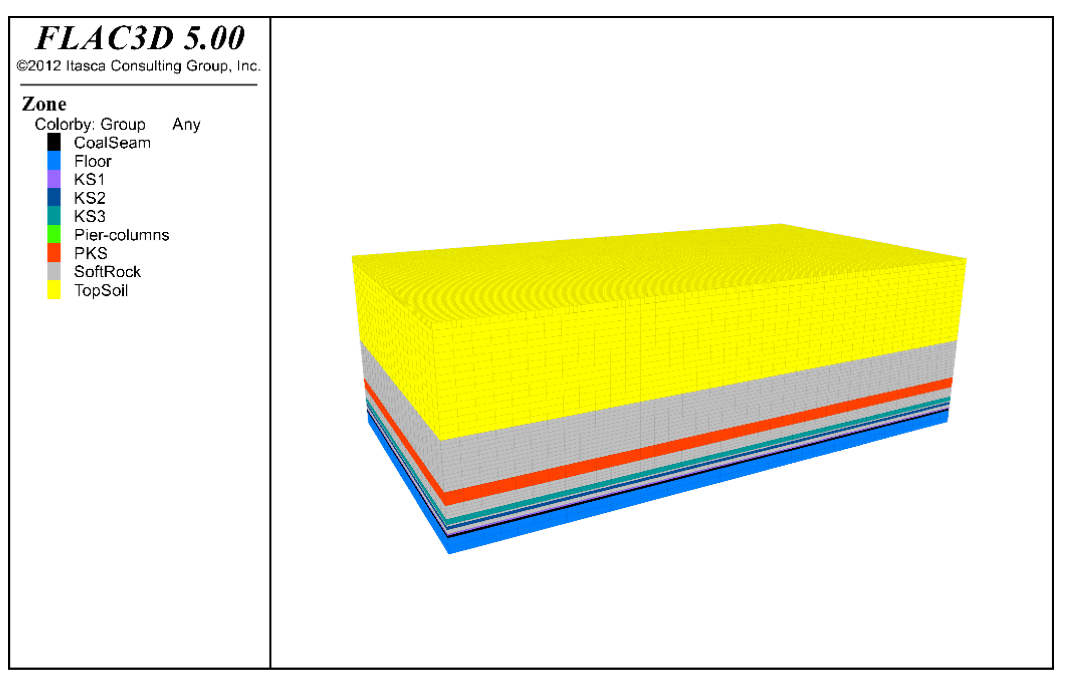
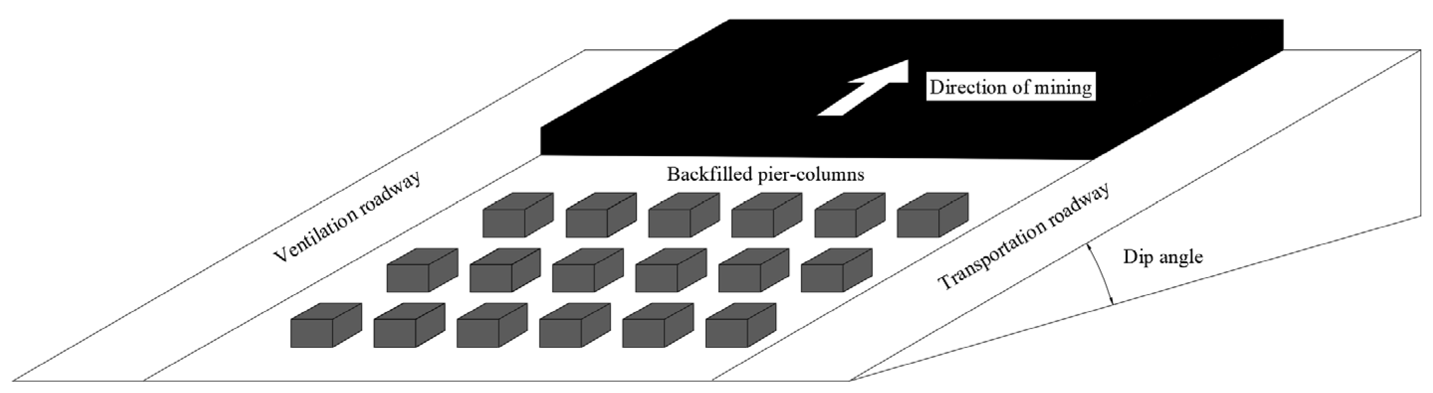
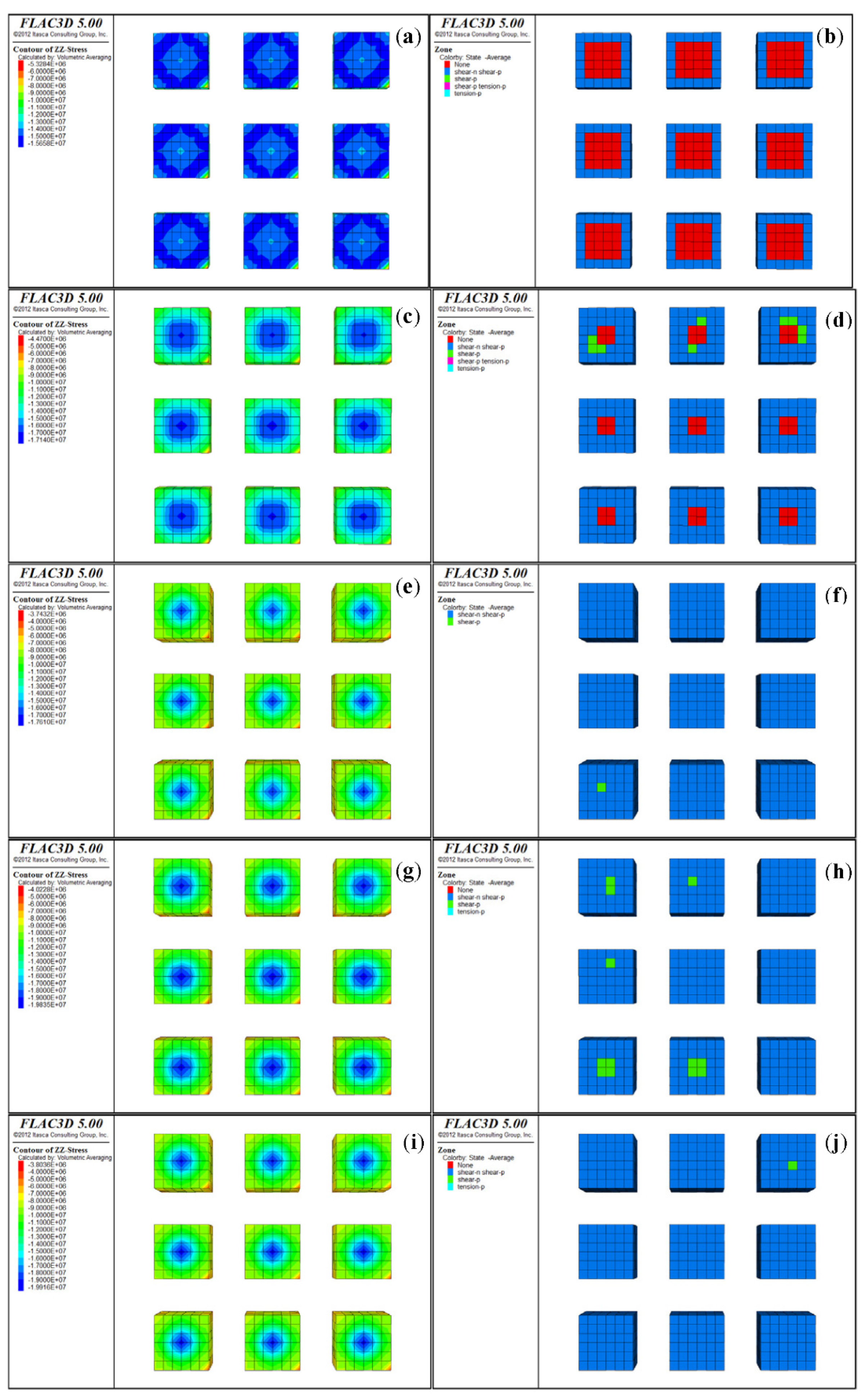
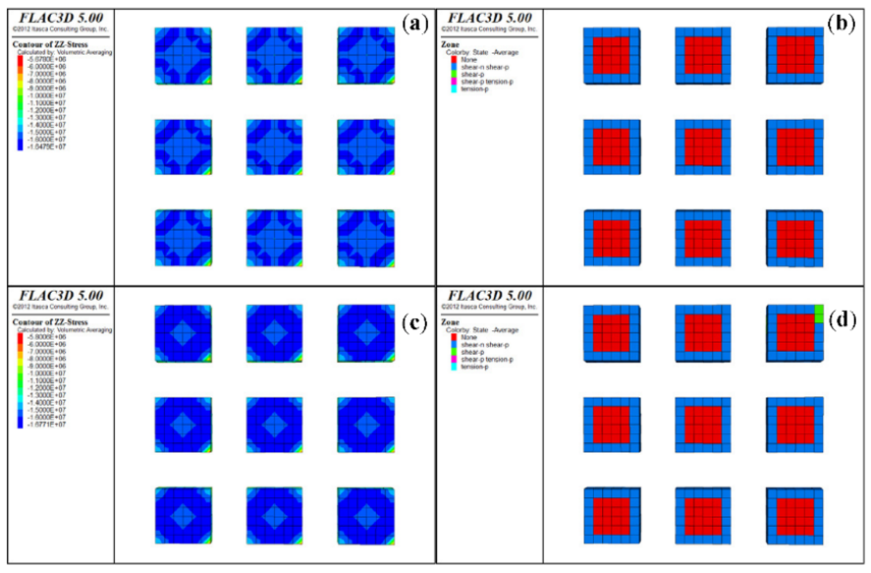
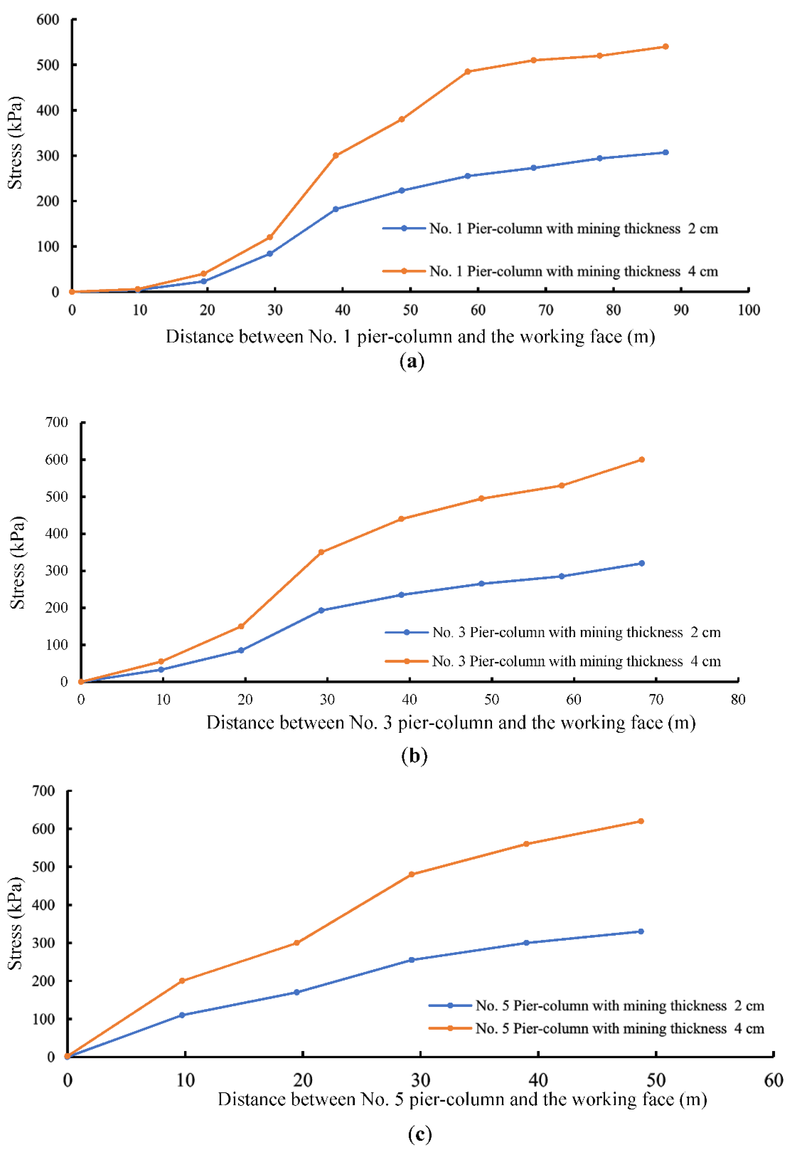
3. Numerical Simulation

Based on the lithology histogram and key stratum identification results as above, a three-dimensional numerical model was established using FLAC3D. In this model, the pier-column has a square-shaped plane, and a side length of 6 m. The height of the coal seam was equal to the height of the pier-column. The spacing between the pier-columns, in the goaf in the strike and dip directions, was also equal and set to 4 m.
The simulation’s model size was 800 m × 400 m × 240 m (length × width × height) (as shown in Figure 2). This model was mainly used to study the plastic zone distribution and stress variation of the pier-column. A numerical model was established by making necessary simplifications to the overlying strata and floor; the mechanical parameters are shown in Table 2.
In the simulation schemes, the mining widths were set to 80, 160, and 240 m, and five mining thicknesses of 1, 1.5, 2, 2.5, and 3 m were selected for each mining width.
We aimed to investigate the impact of the change in the mining thickness and width on the stability of the backfilled pier-column, from the initial stage of backfilling to the stage of a stable overburden movement. The changes in the stress and plastic zone of the pier-column during the experiment were recorded. A monitoring point for the stress was arranged in a pier-column to measure the changes in the stress and plastic zone of the pier-column as the working face advanced.
It can be observed in the numerical simulation results that the measured stress profile of the pier-column had a constant mining width and a variable mining thickness, as shown in Figure 3.
Figure 3 shows that when the distance between the monitoring point and the working surface was within 40 m, the stress of the pier-column increased sharply. After 40 m, the stress still increased, but the stress increased slowly until the maximum was reached, where it became stabilized.
In Figure 4, given the condition that the mining width of the working face was 80 m and when the mining thickness was 1 m, the maximum stress of the pier-column was 8.2 MPa. When the mining thickness was 1.5 m, the maximum stress of the pier-column was 11.3 MPa, which was 1.4 times greater compared with the mining thickness of 1 m. When the mining thickness was 2 m, the maximum stress of the pier-column was 11.5 MPa, similar to when a thickness of 1.5 m was modeled. When the mining thickness was 2.5 m, the maximum stress of the pier-column was 13.8 MPa, which was 1.7 times greater in comparison to when the mining thickness was 1 m. When the mining thickness was 3 m, the maximum stress of the pier-column was 13.9 MPa, which was close to that when the mining thickness was 2.5 m. When the mining width was 160 m or 240 m, it also displayed the similar stress variation behavior. Therefore, it can be considered that the maximum stress of the pier-column basically remained constant when the mining thicknesses were 2.5 m and 3 m.
The proportion of the elastic zone of the pier-column was negatively correlated with the mining thickness of the coal seam (Figure 5). For example, under the condition that the mining width of the working face was 80 m, when the mining thickness was 1 m, the proportion of the elastic zone in the cross-section of the pier-column was 44%, shown as the red area in Figure 5b. When the mining thickness was 1.5 m, the proportion of the elastic zone in the cross-section of the pier-column was 11%, shown as the red area in Figure 5d. When the mining thickness increased to 2 m, the pier-column was entirely in a state of plastic failure after undergoing shear and tensile failure. When the mining thickness continued to increase, the pier-column was still in the completely plastic state, as shown in Figure 5e–j.
When the mining thickness of the working face for the backfilling increased, the plastic zone at the edge of the backfilled pier-column developed inward. In addition, the location of the peak vertical stress moved toward the center, until the peak value became greater than the strength of the pier-column, resulting in instability and failure of the backfilled pier-column. After the pier-column completely failed, the roof was supported by the residual strength. The vertical stress peak was concentrated in the middle of the backfilled pier-column, and there was no elastic core zone.
When the mining width of the working face remained unchanged, the mining thickness had a greater impact on the stability of the backfilled pier-column. With each increase in the mining thickness, the stability of the pier-column decreased sharply. This shows that a significant negative correlation exists between the stability of the pier-column and the mining thickness.
Given the condition that the mining thickness of the working face was 1 m and with different mining widths, the measured stress profile of the pier-column had a constant mining thickness and a variable mining width, as shown in Figure 6.
Comparing the simulation results that are shown in Figure 5b and Figure 6b,d, it can be observed that the main factor that affects the stability of the pier-column is the mining thickness. Meanwhile, the mining width has a relatively small impact on the stability of the pier-column.

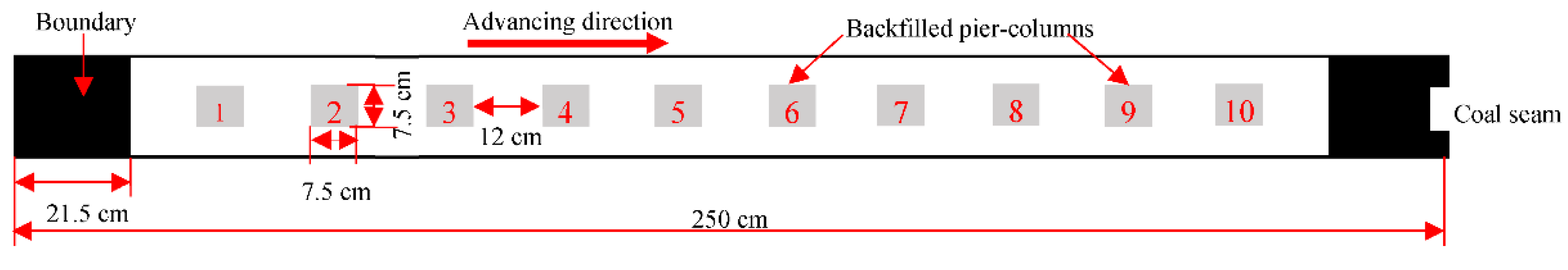
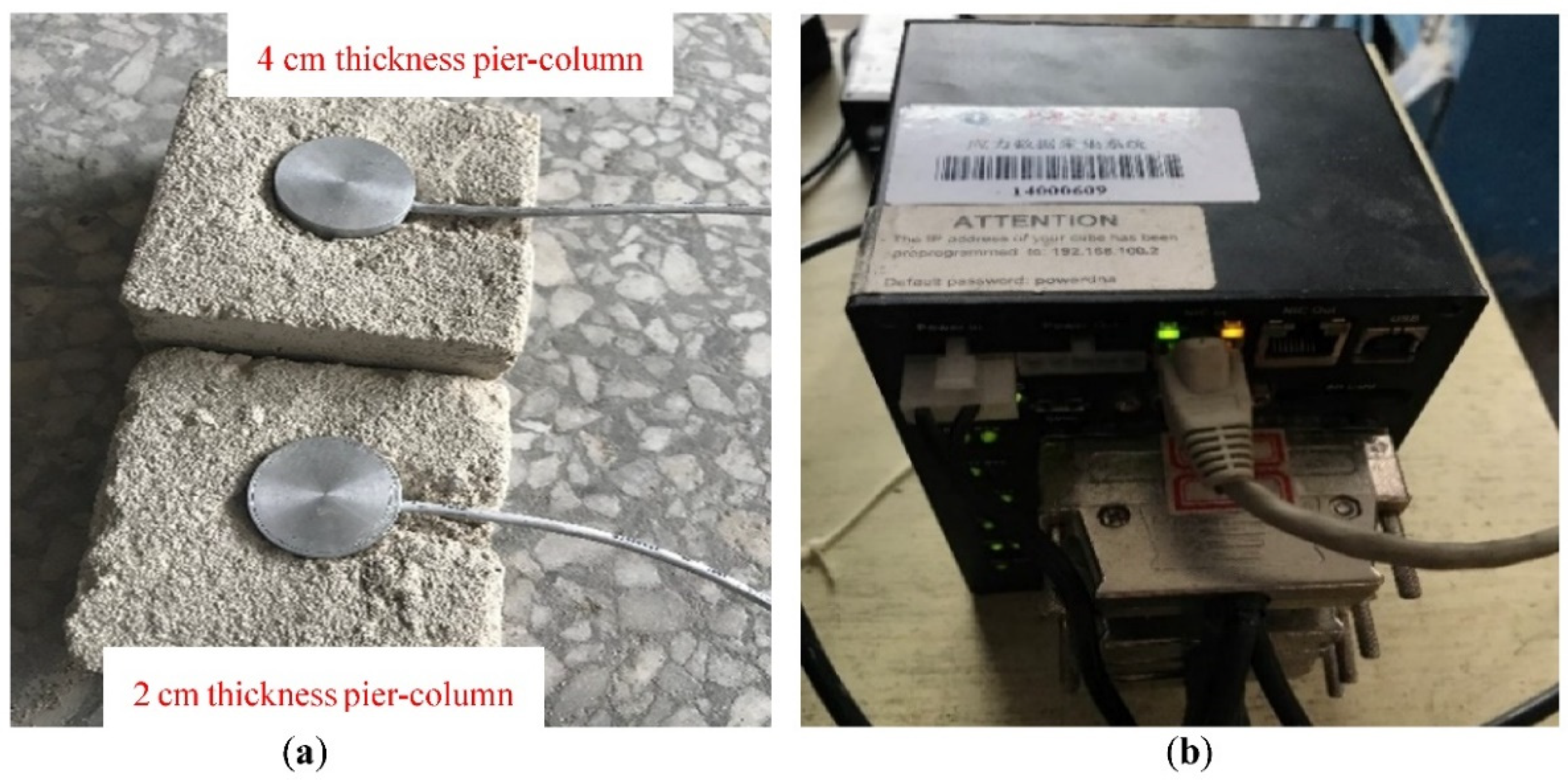
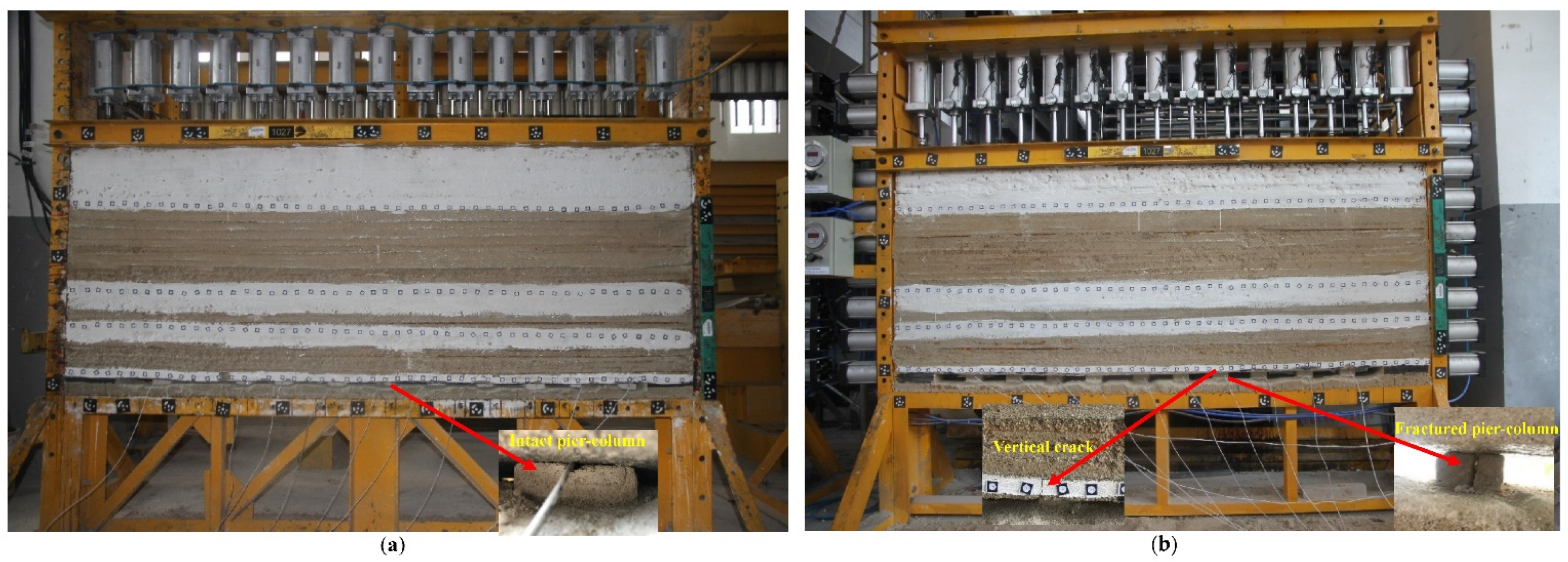
4. Physical Experiments
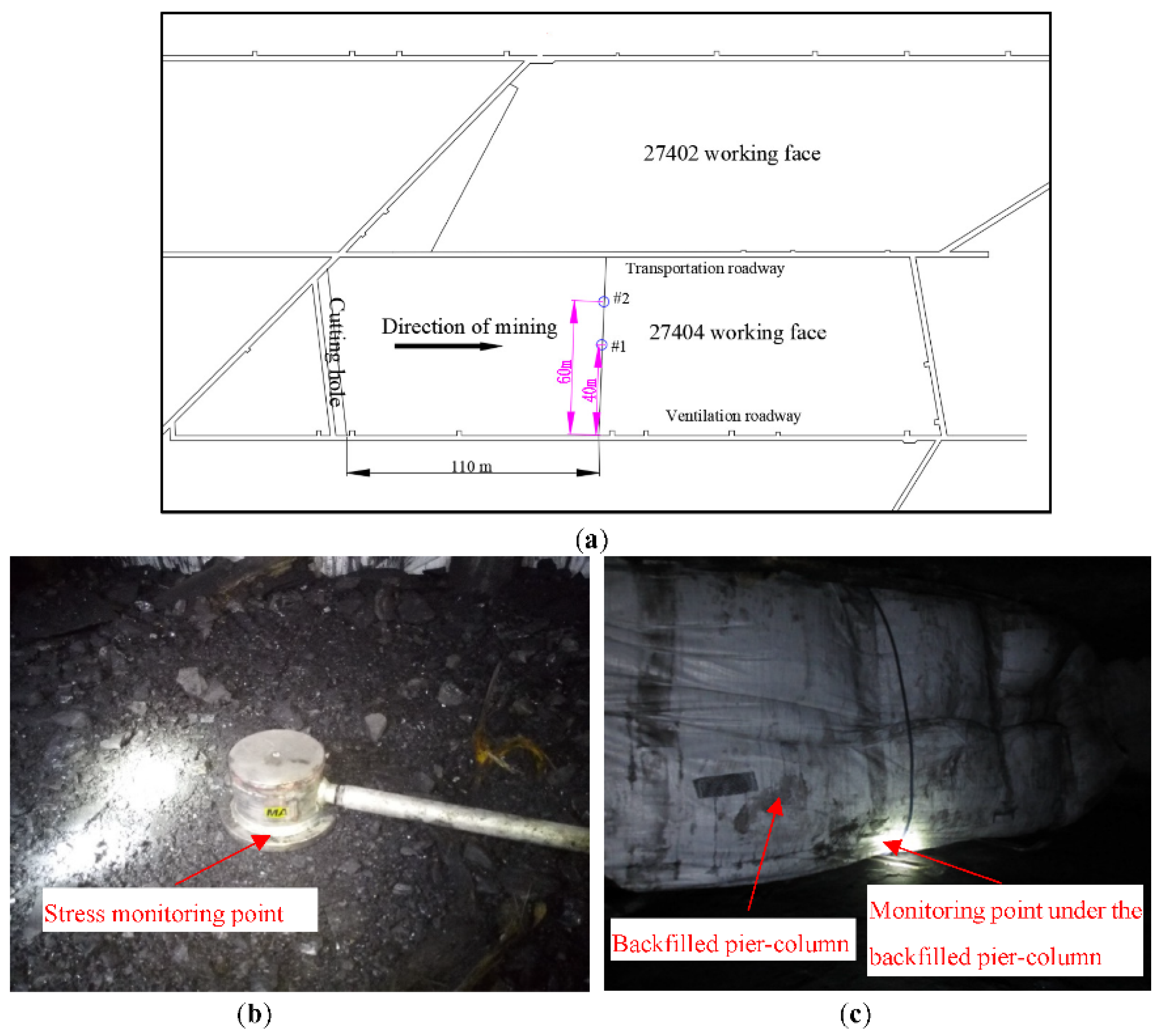
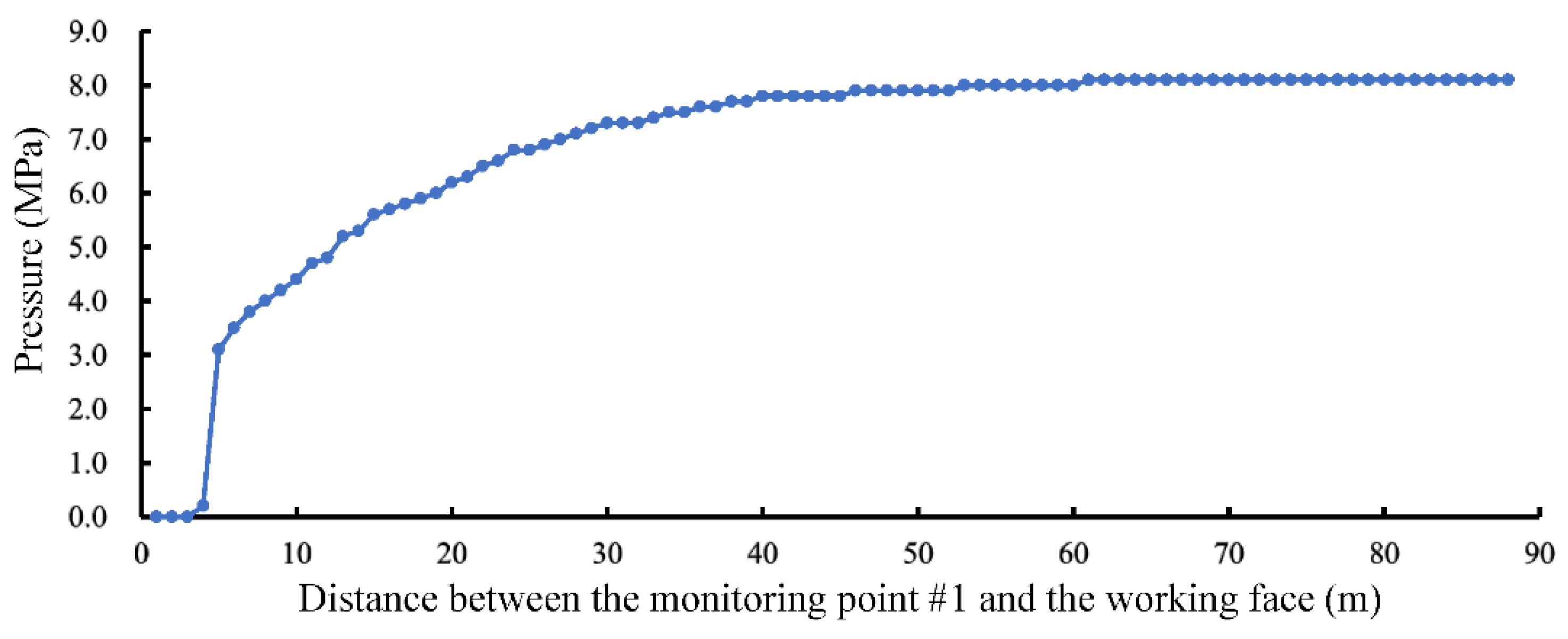
This investigation explored the impact of the mining dimensions on the stability of the backfilled pier-columns. A plane stress model was used to conduct the physical experiments. The length, height and width of the model were 250 cm, 200 cm and 20 cm respectively. These experiments monitored the variation pattern of the vertical stress in the backfilled pier-column.
In accordance with the overlying strata of borehole 8–15, the stratification of the strata has been simplified in the model. Backfilled pier-columns, which had a length of 7.5 cm, width of 7.5 cm, and height of 2 cm or 4 cm were arranged along the width with a row spacing of 12 cm between them. The pier-columns are numbered 1 to 10 from left to right; their exact positions are shown in Figure 7.
The pressure cell was embedded in the prefabricated pier-column. In addition, the data logger was used to collect the stress data in the experiment. The process of the mining and backfilling is illustrated in Figure 8a,b.
In the process of mining the physical model with a mining thickness of 2 cm, no major failure occurred in the pier-column, and the overlying strata were well supported and controlled. The experimental results of the backfilled pier-column are shown in Figure 9a. In the process of mining the physical model with a mining thickness of 4 cm, apparent fractures were found in the pier-column. The residual strength that occurred after the failure of the pier-column still provided strong support to the roof. Cracks appeared in the immediate roof, whereas no cracks or fractures were found in the other strata. The experimental results are shown in Figure 9.
In the two physical models with different mining thicknesses, the stress of the pier-column was monitored from the point of setting the first pier-column to the completion of the experiment. In addition, the stress monitoring curves of No. 1, No. 3, and No. 5 pier-columns were compared and analyzed, as shown in Figure 10.
By comparing the stress of the pier-column under the different mining thickness conditions, it can be observed that when the mining thickness of the working face increased, the stress of the pier-column increased significantly. This shows that the mining thickness has a greater impact on the stress of the pier-column. Based on these results, there is a negative correlation between them. When the stress exceeds the strength of the pier-column, the pier-column will undergo plastic failure.

5. Field Testing

Field stress monitoring of the pier-column was carried out in working face 27404. The thickness of the working face iwass nearly 1 m; it was a near-horizontal coal seam. The mining depth and mining width were about 240 m and 80 m, respectively. Based on the stress data that were obtained through monitoring, the changes in the load on the goaf were understood, thus achieving the purpose of grasping the actual load-bearing performance of the backfilled pier-column.
The width of working face (27404) was approximately 80 m, and the mining thickness was nearly 1 m. When the working face advanced to a distance of 110 m from the cutting hole, two monitoring points were arranged in the goaf to monitor the stress of the backfilled pier-columns. Stress-monitoring points #1 and #2 were arranged at around 40 m and 60 m from the ventilation roadway, respectively, for on-site stress monitoring, as shown in Figure 11a.
Before the backfilling bag was filled, the stress monitoring point was placed between the backfilling bag and the floor, as shown in Figure 11b. After the backfilling bag was filled, the stress-monitoring point was located between the backfilled pier-column and the floor, as shown in Figure 11c.
Beginning on 8 October 2017, observations of the field stress of the pier-columns in the goaf were conducted for nearly three consecutive months. On the third day after the stress monitoring system was installed, the signal transmission cable of monitoring point #2 was interrupted so only the data from monitoring point #1 were obtained. The final stress profile is shown in Figure 12.
It can be observed from Figure 12 that when the distance between monitoring point #1 and the working face was within 3 m, the maximum stress was 0.2 MPa. The reason for this is that after the slurry was poured into the backfilling bag, its strength was low during the hardening stage and the roof could not be effectively supported. At this stage, the main support was provided by the single hydraulic prop, and the backfilled pier-column had not yet borne the load of the overlying strata. When the distance between monitoring point #1 and the working face was 4 m, the stress of the backfilled pier-column increased rapidly to 3.1 MPa. This is because the strength of the backfilled pier-column met the design requirements. Meanwhile, the hydraulic prop was withdrawn, which caused a part of the load from the overlying strata to be exerted onto the backfilled pier-column. As the working face advanced, the distance between monitoring point #1 and the working face gradually increased, and the area of the overlying roof that was supported by the pier-column also increased. At this time, the load gradually increased. When the distance between monitoring point #1 and the working face was within 40 m, the stress of the backfilled pier-column increased overall. When the distance was 40 m, the stress was 7.8 MPa. When the distance exceeded 40 m, the stress was stable around 8 MPa. Thereafter, the loading stress of the backfilled pier-column did not increase as the distance continued to increase. This indicates that the pier-column had reached a stable and elastic state, and it could thus effectively support the overlying strata.

6. Conclusions

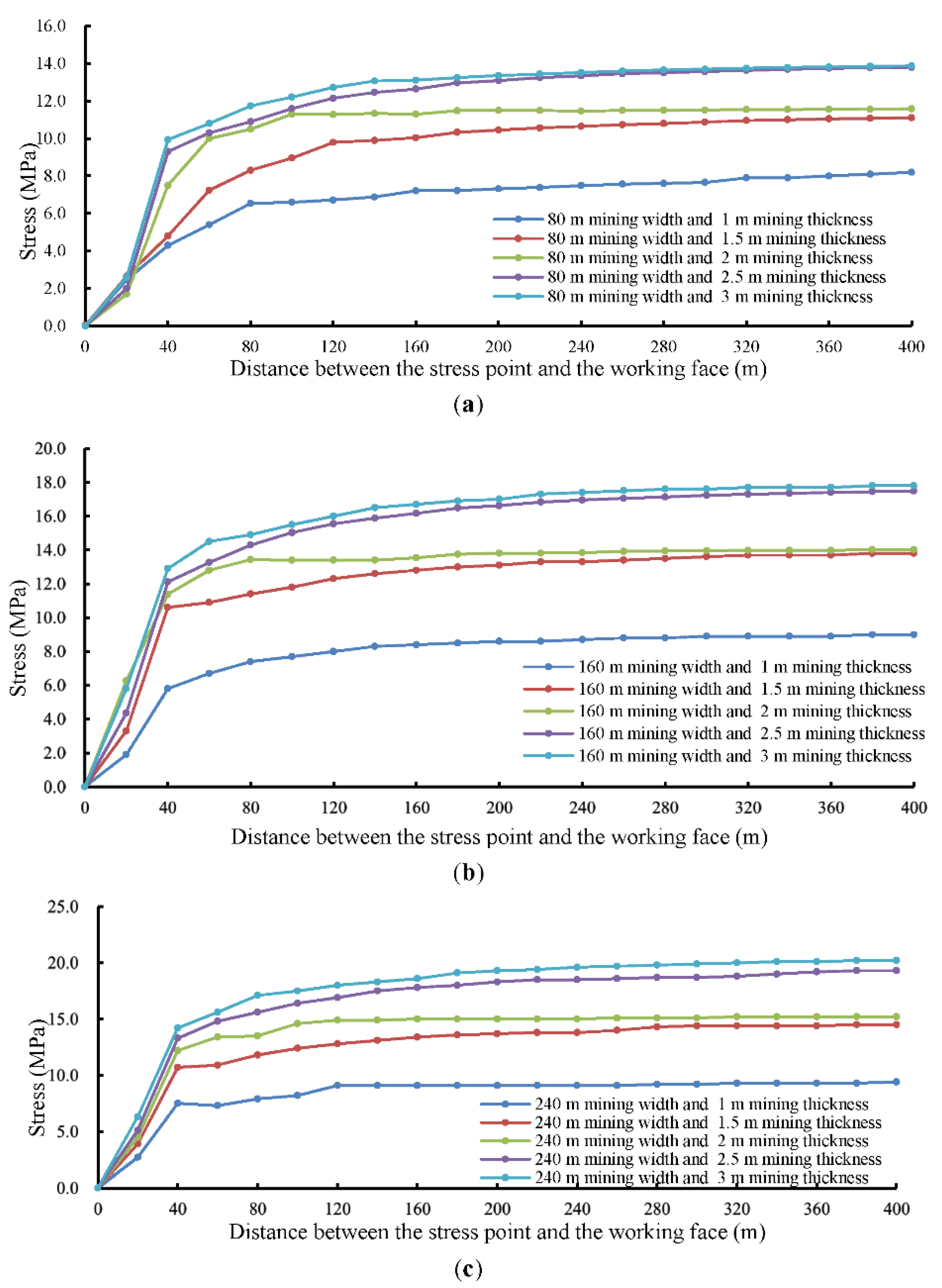
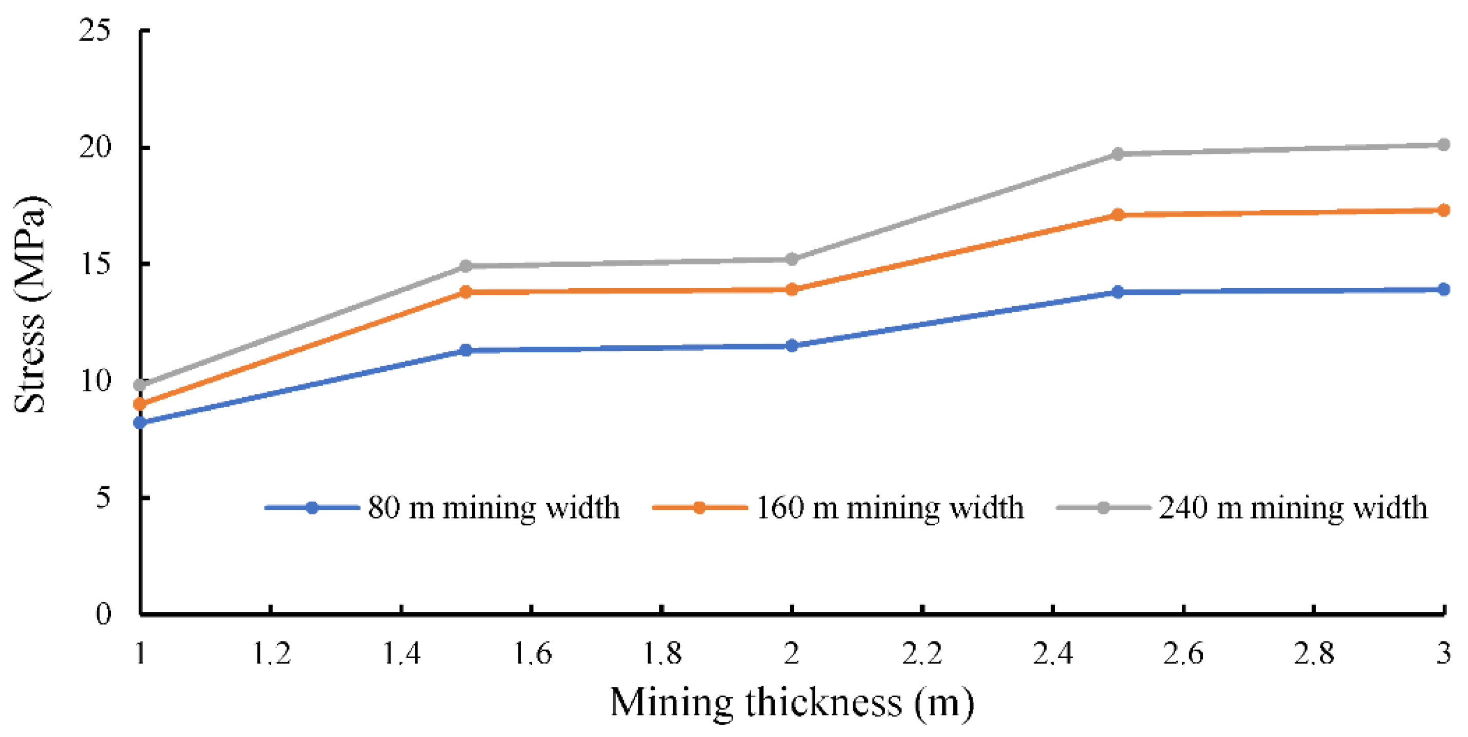
  • The results of both the numerical simulations and physical experiments indicated that the mining thickness has a relatively large impact on the stability of the backfilled pier-column. Each time the mining thickness increased, the stress of the pier-column was significantly enhanced, and the stability of the pier-column remarkably decreased. On the other hand, the mining width has relatively little effect on the stability of the pier-column.
  • After field testing, it was obtained that the distance at which the stress of the backfilled pier-column reached stability was about 40 m, which was in close agreement with the numerical simulation results. It demonstrated that when the working face has a mining thickness of nearly 1 m and a mining width of 80 m, the backfilled pier-column can maintain good stability under the designed parameters, and it also can support the overlying strata of the goaf after mining.
  • If the mining thickness or mining width of the working face changes on-site in the future, the parameters of the backfilled pier-column should be optimized and improved to ensure the stability of the pier-column.

Author Contributions

Conceptualization, J.X. (Jianlin Xie) and W.Z.; formal analysis, J.X. (Jianlin Xie); writing—original draft preparation, J.X. (Jianlin Xie) and W.Z.; writing—review and editing, X.W. and J.X. (Jialin Xu); simulation experiment, X.W. and L.W.; field testing, J.X. (Jianlin Xie) and L.W.; validation, W.Z. and J.X. (Jialin Xu). All authors have read and agreed to the published version of the manuscript.

Funding

National Natural Science Foundation of China (52074265).

Institutional Review Board Statement

Not applicable.

Informed Consent Statement

Not applicable.

Data Availability Statement

The data presented in this study are available on request from the corresponding author.

Acknowledgments

We extended our sincere thanks to the relevant staff at the State Key Laboratory of Coal Resources and Safe Mining for the simulation experiment. We also extended our sincere thanks to the relevant staff of Wangzhuang Coal Mine for their help in field testing.

Conflicts of Interest

The authors declare no conflict of interest.

References

  1. Park, J.H.; Ji, S.W.; Ahn, J.W. Recycling of coal ash and related environmental issues in Australia. J. Korean Inst. Resour. Recycl. 2019, 28, 15–22. [Google Scholar]
  2. Hume, R.G.; Searle, G.K. Improved recovery in highwall mining using backfill ACARP Project C3052. Aust. Inst. Min. Metall. Pub. Ser. 1998, 98, 197–205. [Google Scholar]
  3. Plewa, F.; Strozik, G.; Sobota, J. Waste utilization in hydraulic backfill. BHR Group Conf. Ser. Pub. 1999, 14, 97–111. [Google Scholar]
  4. Bukowski, P.; Niedbalska, K. The analysis of selected properties of solid rock materials designed for shafts liquidation. Int. Multidiscip. Sci. GeoConf.-SGEM 2013, 2, 467–474. [Google Scholar]
  5. Kump, D. Backfill-Whatever it takes. Min. Eng. 2001, 53, 50–52. [Google Scholar]
  6. Moellerherm, S.; Martens, P.N. Use of copper mine tailings as paste backfill material in mining operations—Approach to minimise land occupation? In Tailings Mine Waste ’02; CRC Press: Boca Raton, FL, USA, 2002; pp. 149–153. [Google Scholar]
  7. Hollinderbaumer, E.W.; Mez, W. Viscosity controlled production of high-concentration backfill pastes. Aust. Inst. Min. Metall. Pub. Ser. 1998, 98, 43–47. [Google Scholar]
  8. Benzaazoua, M.; Bussiere, B.; Demers, I.; Aubertin, M.; Fried, E.; Blier, A. Integrated mine tailings management by combining environmental desulphurization and cemented paste backfill: Application to mine Doyon, Quebec, Canada. Miner. Eng. 2008, 21, 330–340. [Google Scholar] [CrossRef]
  9. Behera, S.K.; Ghosh, C.N.; Mishra, K.; Mishra, D.P.; Singh, P.; Mandal, P.K.; Buragohain, J.; Sethi, M.K. Utilisation of lead-zinc mill tailings and slag as paste backfill materials. Environ. Earth Sci. 2020, 79, 389. [Google Scholar] [CrossRef]
  10. Nigam, G.K.; Sahu, R.K.; Sinha, M.K.; Deng, X.; Singh, R.B.; Kumar, P. Field assessment of surface runoff, sediment yield and soil erosion in the opencast mines in Chirimiri area, Chhattisgarh, India. Phys. Chem. Earth 2017, 101, 137–148. [Google Scholar] [CrossRef]
  11. Bazaluk, O.; Petlovanyi, M.; Lozynskyi, V.; Zubko, S.; Sai, K.; Saik, P. Sustainable Underground Iron Ore Mining in Ukraine with Backfilling Worked-Out Area. Sustainability 2021, 13, 834. [Google Scholar] [CrossRef]
  12. Basarir, H.; Bin, H.; Fourie, A.; Karrech, A.; Elchalakani, M. An adaptive neuro fuzzy inference system to model the uniaxial compressive strength of cemented hydraulic backfill. Min. Miner. Depos. 2018, 12, 1–12. [Google Scholar] [CrossRef]
  13. Sotskov, V.; Dereviahina, N.; Malanchuk, L. Analysis of operation parameters of partial backfilling in the context of selective coal mining. Min. Miner. Depos. 2019, 13, 129–138. [Google Scholar] [CrossRef] [Green Version]
  14. Iordanov, I.; Novikova, Y.; Simonova, Y.; Yefremov, O.; Podkopayev, Y.; Korol, A. Experimental characteristics for deformation properties of backfill mass. Min. Miner. Depos. 2020, 14, 119–127. [Google Scholar] [CrossRef]
  15. Rybak, J.; Tyulyaeva, Y.; Kongar-Syuryun, C.; Khayrutdinov, A.M.; Akinshin, I. Geomechanical substantiation of parameters of technology for mining salt deposits with a backfill. Min. Sci. 2021, 28, 19–32. [Google Scholar]
  16. Zhou, H.Q.; Hou, C.J.; Sun, X.K.; Qu, Q.D.; Chen, D.J. Solid waste paste filling for none-village-relocation coal mining. J. China Univ. Min. Technol. 2004, 2, 30–34. [Google Scholar]
  17. Wang, Z.; Yu, W.J.; Liu, F.F. The Materialization Characteristics and Ratio of a New Soil Paste Filling Material. Adv. Civ. Eng. 2020, 2020, 6645494. [Google Scholar]
  18. Miao, X.X.; Zhang, J.X.; Guo, G.L. Study on waste-filling method and technology in fully-mechanized coal mining. J. Chin. Coal Soc. 2010, 35, 1–6. [Google Scholar]
  19. Huang, P.; Spearing, A.J.S.; Feng, J.; Jessu, K.V.; Guo, S. Effects of solid backfilling on overburden strata movement in shallow depth longwall coal mines in West China. J. Geophys. Eng. 2018, 15, 2194–2208. [Google Scholar] [CrossRef] [Green Version]
  20. Xuan, D.Y.; Xu, J.L.; Wang, B.L.; Teng, H. Borehole investigation of the effectiveness of grout injection technology on coal mine subsidence control. Rock Mech. Rock Eng. 2015, 48, 2435–2445. [Google Scholar] [CrossRef]
  21. Wang, B.L.; Xu, J.L.; Xuan, D.Y. Time function model of dynamic surface subsidence assessment of grout-injected overburden of a coal mine. Int. J. Rock Mec. Min. 2018, 104, 1–8. [Google Scholar] [CrossRef]
  22. Feng, G.M.; Sun, C.D.; Wang, C.Z.; Zhou, Z. Research on goaf filling methods with super high-water material. J. Chin. Coal Soc. 2010, 35, 1963–1968. [Google Scholar]
  23. Zhu, W.B.; Yu, S.C.; Xuan, D.Y.; Shan, Z.J.; Xu, J.L. Experimental study on excavating strip coal pillars using caving zone backfill technology. Arab. J. Geosci. 2018, 11, 554. [Google Scholar] [CrossRef]
  24. Zhu, X.J.; Guo, G.L.; Liu, H.; Chen, T.; Yang, X.Y. Experimental research on strata movement characteristics of backfill–strip mining using similar material modeling. Bull. Eng. Geol. Environ. 2019, 78, 2151–2167. [Google Scholar] [CrossRef]
  25. Wang, Y.; Huang, Y.C.; Hao, Y.X. Experimental study and application of rheological properties of coal gangue-fly ash backfill slurry. Process 2020, 8, 284. [Google Scholar] [CrossRef] [Green Version]
  26. Xie, J.L.; Zhu, W.B.; Xu, J.L.; Wen, J.H.; Liu, C.Z. A study on the bearing effect of pier-column backfilling in the goaf of a thin coal seam. Geosci. J. 2016, 20, 361–369. [Google Scholar] [CrossRef]
  27. Zhu, W.B.; Xu, J.M.; Xu, J.L.; Chen, D.Y.; Shi, J.X. Pier-column backfill mining technology for controlling surface subsidence. Int. J. Rock Mec. Min. 2017, 96, 58–65. [Google Scholar] [CrossRef]
  28. Wang, X.Z.; Xie, J.L.; Xu, J.L.; Zhu, W.B.; Wang, L.M. Effects of Coal Mining Height and Width on Overburden Subsidence in Longwall Pier-Column Backfilling. Appl. Sci. 2021, 11, 3105. [Google Scholar] [CrossRef]
  29. Qian, M.G.; Miao, X.X.; Xu, J.L. Key strata theory in strata control. J. Chin. Coal Soc. 1996, 21, 225–230. [Google Scholar]
Figure 1. Schematic diagram of pier-column backfilling.
Applsci 11 09640 g001
Figure 2. Numerical model.
Applsci 11 09640 g002
Figure 3. Stress profile of the backfilled pier-column with a constant mining width and variable mining thickness: (a) 80 m width; (b) 160 m width; (c) 240 m width.
Applsci 11 09640 g003
Figure 4. Maximum value of the stress of the backfilled pier-column as a function of mining width and mining thickness.
Applsci 11 09640 g004
Figure 5. Distribution of the vertical stress and elastic zone with a mining width of 80 m and a variable mining thickness: (a) Vertical stress of 1 m thickness; (b) elastic zone of 1 m thickness; (c) vertical stress of 1.5 m thickness; (d) elastic zone of 1.5 m thickness; (e) vertical stress of 2 m thickness; (f) elastic zone of 2 m thickness; (g) vertical stress of 2.5 m thickness; (h) elastic zone of 2.5 m thickness; (i) vertical stress of 3 m thickness; (j) elastic zone of 3 m thickness.
Applsci 11 09640 g005
Figure 6. Distribution of the stress and elastic zone with a mining thickness of 1 m and a variable mining width: (a) vertical stress of 160 m width; (b) elastic zone of 160 m width; (c) vertical stress of 240 m width; (d) elastic zone of 240 m width.
Applsci 11 09640 g006
Figure 7. The positions of the pier-columns.
Applsci 11 09640 g007
Figure 8. Physical experiments: (a) stress cell in different thickness backfilled pier-columns; (b) data logger.
Applsci 11 09640 g008
Figure 9. View of the bearing performance of backfilled pier-column with a different mining thickness: (a) 2 cm; (b) 4 cm.
Applsci 11 09640 g009
Figure 10. Curve of the stress of different pier-columns: (a) No. 1; (b) No. 3; (c) No. 5.
Applsci 11 09640 g010
Figure 11. Field testing: (a) the arrangement of the stress monitoring points in working face 27404; (b) before pier-column backfilling; (c) after pier-column backfilling.
Applsci 11 09640 g011
Figure 12. Stress profile of backfilled pier-column from monitoring point #1.
Applsci 11 09640 g012
Table 1. Lithology histogram and key stratum identification results of the No. 8–15 borehole.
Layer NumberThickness (m)Buried Depth (m)LithologyKey Stratum
28127.6127.6Loose soil
273.99131.59Fine sandstone
262.29133.88Mudstone
254.8138.68Siltstone
243.35142.06Mudstone
239.74151.77Fine sandstone
228.25160.02Mudstone
212.17162.19Fine sandstone
204.28166.47Mudstone
193.18169.65Siltstone
188.47178.12Fine sandstone
173.67181.79Mudstone
164.07185.86Siltstone
152.77188.63Mudstone
1415.82204.45Fine sandstonePrimary key stratum (PKS)
133.77208.22Mudstone
120.8209.02Fine sandstone
112.97211.99Mudstone
108.06220.05Fine sandstone
96.8226.85SiltstoneKey stratum 3 (KS3)
81.56228.41Mudstone
70.7229.11Siltstone
63.98233.09Fine sandstoneKey stratum 2 (KS2)
51.3234.39Mudstone
41.27235.66Siltstone
33.1238.76Mudstone
21.36240.12Fine sandstoneKey stratum 1 (KS1)
10.83240.95Coal seam
Table 2. Mechanical parameters.
LithologyDensity (kg/m3)Tensile Strength (MPa)Bulk Modulus (GPa)Shear Modulus (GPa)Cohesive Force (MPa)Angle of Friction (°)
Top soil18000.020.020.0140.0518
Key stratum25004.504.002.405.0040
Soft rock20002.202.501.303.0028
Pier-columns25003.003.002.104.0030
Coal seam14002.002.002.402.0025
Floor25004.504.002.405.0040
Publisher’s Note: MDPI stays neutral with regard to jurisdictional claims in published maps and institutional affiliations.

