1. Introduction
The interest in Free Electron Laser (FEL), during the last decade, has moved toward devices producing X-ray beams with high brilliance matching the requirements for many applications such as nuclear materials detection [
1], small-angle X-ray scattering [
2], phase contrast imaging [
3], macromolecular X-ray crystallography for drug discovery [
4] and X-ray microscopy [
5].
The Linac Coherent Light Source (LCLS) at SLAC National Accelerator Laboratory [
6], FLASH at DESY Deutsches Elektronen-Synchrotron [
7] with other advanced X-ray FEL [
8,
9,
10,
11,
12,
13] provide, or have been designed to provide, high-brightness X-ray beams, but size, cost and operational complexity are the main drawbacks for a widespread use in small laboratories, hospitals, universities.
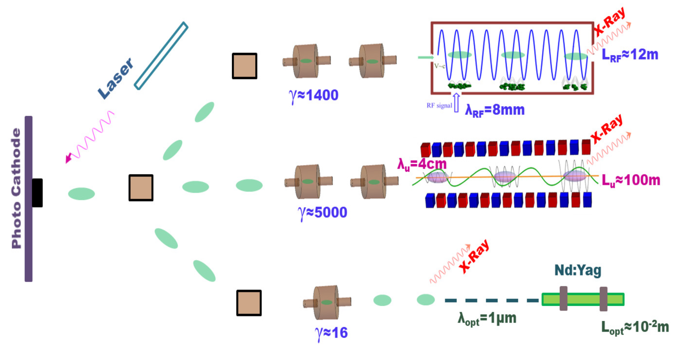
The X-FEL technology is based on two pillars, high-energy (multi-Gev) high-quality electron beam Linacs and hundred-meters-long undulators. A high-brilliance X-ray device demands, accordingly, large facilities and therefore any progress towards “compact” X-ray FELs requires technological improvements in terms of high-gradient accelerators and/or short “wavelength” undulators. The last possibility will be considered in this paper.
The availability of powerful electromagnetic sources (lasers or RF sources) offers the possibility of replacing magnetic with electromagnetic undulators. The advantage would be that of reducing both the size of the undulator and the energy of the e-beam (electron beam).
In
Figure 1 we sketch out the scaling of the beam energy and of the undulator length, with magnetic or RF wave undulators. The last option comprises either laser and RF solutions.
The use of an electromagnetic undulator pumped by a GHz RF field allows, for the same FEL wavelength, to reduce the energy of the electron beam by several units and the length of the magnet by more than one order of magnitude.
We provide below a preliminary idea of how electron beam and Radio Frequency Undulators (RFU) combine to drive an X-ray FEL Self-Amplified Spontaneous Emission (SASE) device. It is evident, as underscored below, that the price to be payed to exploit RFU, in a FEL-SASE operation, is that of employing high intensity fields. We do not specify, for the moment, any electromagnetic source, we fix a reference RF power and the relevant operating wavelength to specify electron beam parameters suitable for FEL SASE X-ray operation.
It is well known that, from the conceptual point of view, wave or magnetic undulators do not change the FEL physics and the associated design criteria. In both cases, the emission process can be traced back to Compton/Thomson backscattering and after establishing the suitable correspondence, in terms of FEL strength parameter, most of the design strategy and scaling properties work as in the case of “ordinary” magnetostatic undulators [
14,
15].
One of the pivotal parameters ruling the electron dynamics inside the undulator is the so-called strength K which measures the amount of electron transverse momentum, acquired inside the undulator, allowing the coupling between the e-beam and a transverse co-propagating wave. The parameter K is specified
- (a)
for the magnetostatic case with on-axis field intensity
and period
, by [
16]
- (b)
for a RF/wave undulator with the microwave field power density
, by [
17]
where the subscripts
stand for magnetic and wave, respectively, while
e,
denote the electron charge and mass, respectively,
—the RF wavelength and
c is the speed of light.
The electron relativistic factor
is linked to the
K parameter, FEL operating wavelength
and undulator period by
being
, for a linearly polarized RF wave.
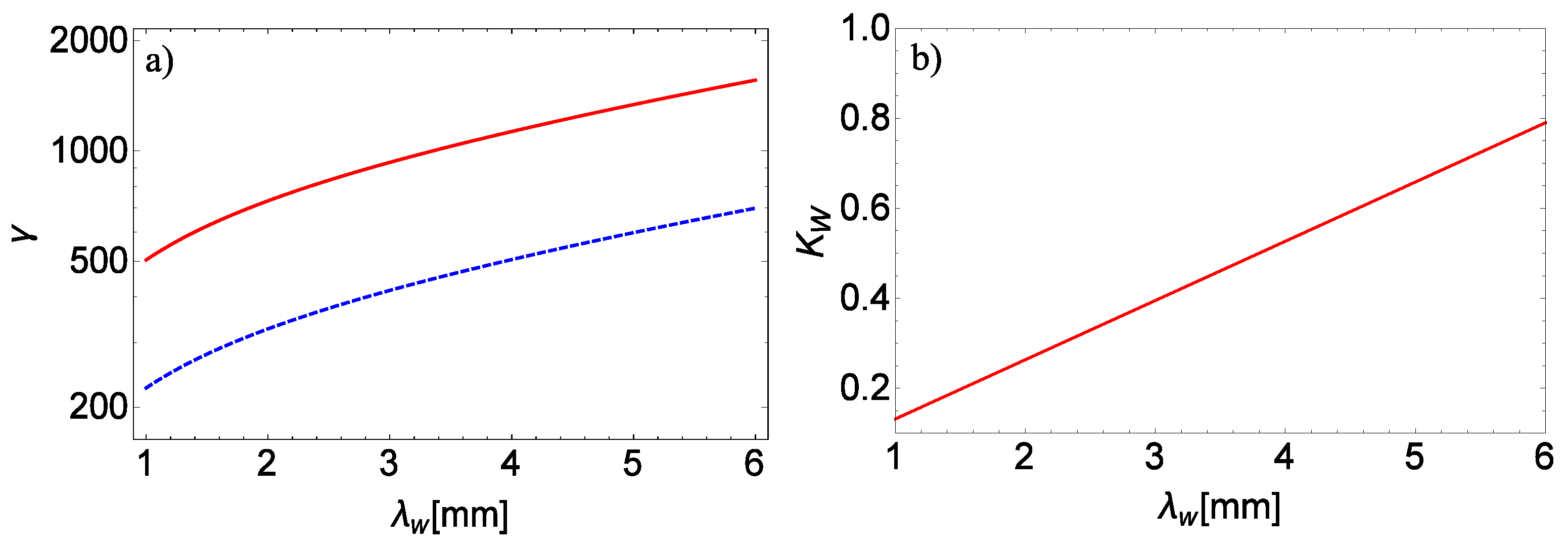
In
Figure 2 we report
vs
for two different values of the FEL wavelength (
nm and
nm). The corresponding
values are apparently small, for a safe FEL operation (below
for the region of interest). The choice of a sufficiently large
(with a suitable combination of energy and current values) ensures the saturation in a reasonable saturation length.
The key quantity of FEL dynamics is the so-called Pierce parameter [
18]
where
, with
, is the electron beam current density, namely the current
I divided by the transverse area of the electron beam (with section
) and
the Bessel function factor (which for circular polarized wave can be taken to be 1 [
15]).
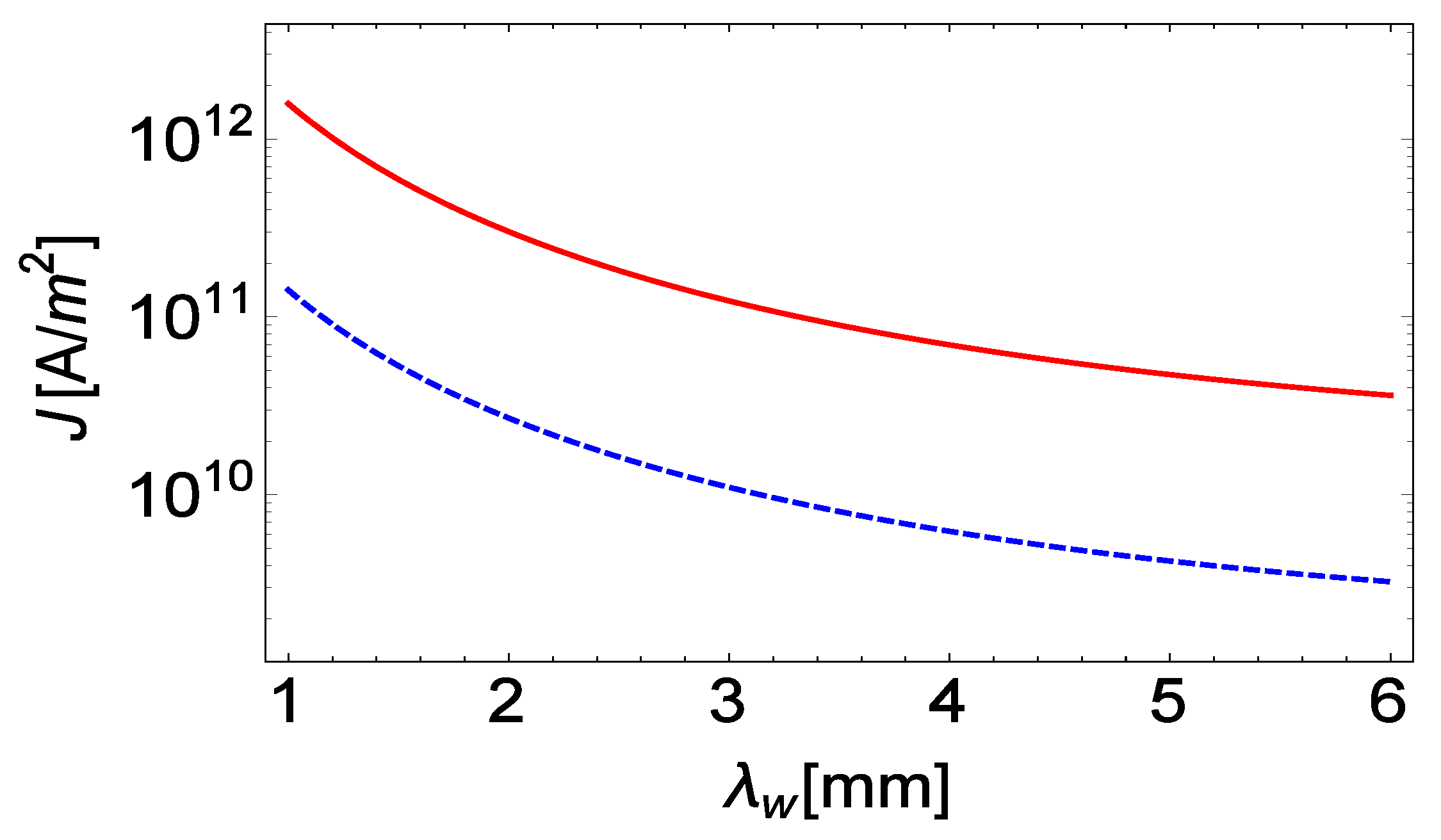
In
Figure 3 we report the beam current density, necessary to support a Pierce parameter of around
for two different FEL operating wavelengths, following from Equation (
4).
The importance of
stems from the fact that it controls all the significant parameters for the SASE FEL, like the gain length specified in [
18],
which in turns defines the saturation length
, which can be quantified as [
18]
The nonideal beam qualities (finite relative energy spread and emittance) determine a dilution of the gain and a consequent increase of the saturation length. The
parameter is helpful to quantify these detrimental contributions. The effect of the relative energy spread on the saturation length is, e.g., negligible if [
18]
with the chosen value of
we expect an undulator length (for
mm) of about 2 m and a beam with relative energy spread around
‰.
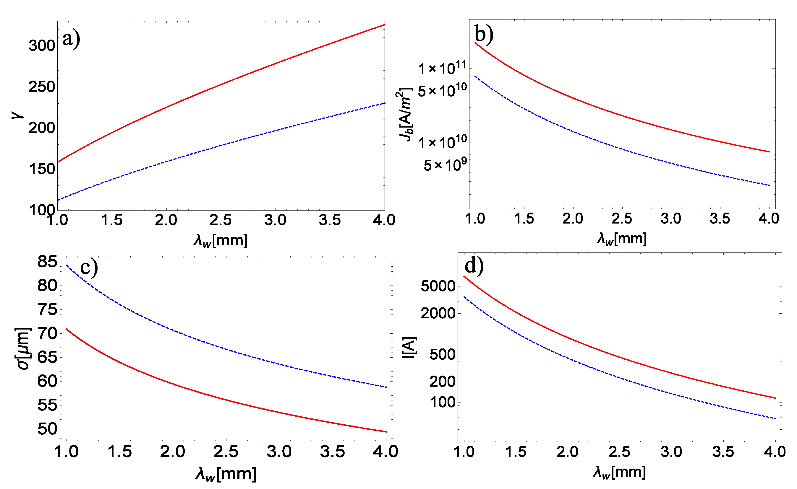
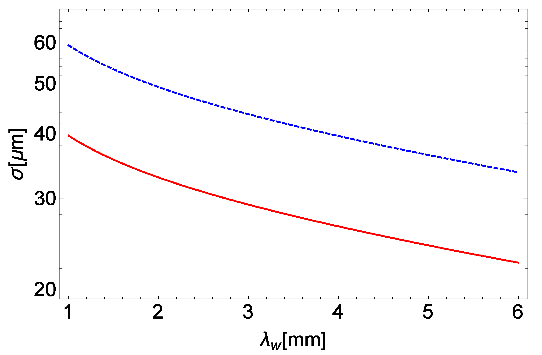
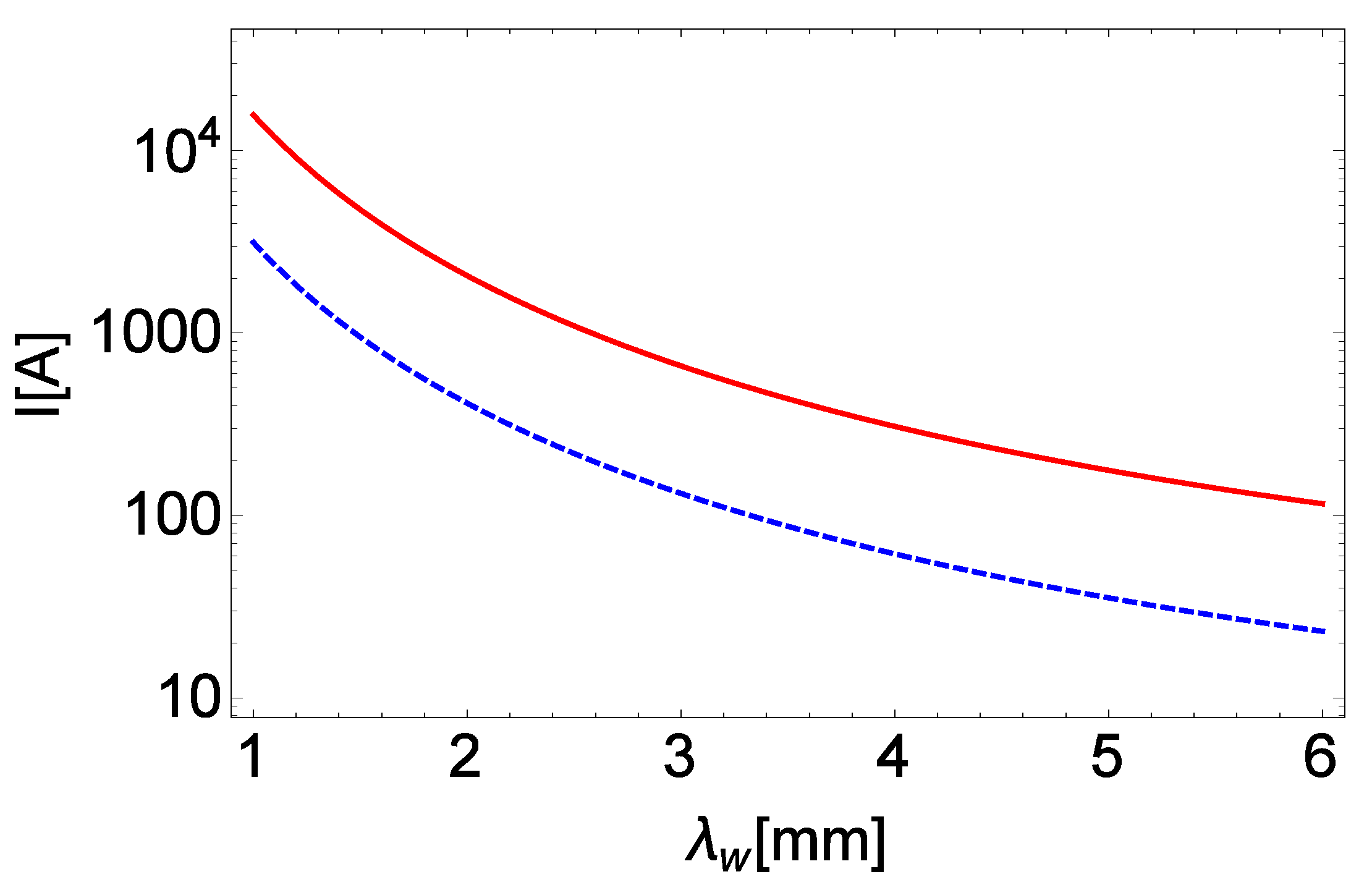
The request on the electron beam parameters in terms of energy and current does not appear challenging. If we consider a beam with a normalized emittance of 1 mm·mrad and assume that it is focused with an average transverse section of less than 60
m (for
nm), along the interaction region, the request on the necessary peak current are constrained within reasonable limits (see
Figure 4 and
Figure 5).
The request, regarding the electron beam parameters, becomes challenging (in terms of peak current) for the operation at short FEL wavelength and relax with increasing . A large amount of power density necessary to obtain reasonable strength undulator values is not a secondary issue and will be carefully discussed in the concluding section.
The scientific literature on the subject of RF undulators has significantly grown in the past and a partial list can be found in [
19,
20,
21,
22,
23,
24,
25,
26,
27,
28,
29].
We would like to underscore that the design numbers we have foreseen can be made more accessible at short if we consider FEL operation in the VUV-X region, which requires low-energy electron beams. We have not specified yet the type of source providing the RFU. The region above 1–9 mm can be achieved with gyrotrons, gyro-klystrons or any other device (see below). Even though all these sources are candidates for RFU, a few elements of discussion are necessary to decide in favor of one or the other.
Gyrotrons work as oscillators and the only way to drive several undulator sections is to be phase locked. The drawback of this configuration is that stable phase locking oscillator operates at 10% only of the locked power. Such an efficiency drop makes this solution scarcely appealing and therefore will not be discussed here. The gyroklystron is a promising source [
30]. It operates at 3 mm wavelength, however, for shorter wavelength the size of the rf cavity has to be reduced too, which will reduce the output power due to the breakdown problems. The peak power of those amplifiers is around 100 kW and the duty factor is about
. It is possible to use the gyro-TWT [
31]. Its peak power is 80–100 kW at 60–80 GHz.
The Cyclotron Auto Resonance Maser (CARM) [
32,
33] promises good performances in the region 1–5 mm, therefore we choose it as RFU candidates in the forthcoming discussion. In
Section 2, we summarize the physics of CARM and fix the design conditions to get sufficient power for RFU operation. In
Section 3 we discuss an actual RFU configuration and discuss the associated critical issues.
2. CARM as a Source of RF Undulator
The CARM is a Free Electron device representing the transition element between microwave tubes and FELs, as nowadays conceived.
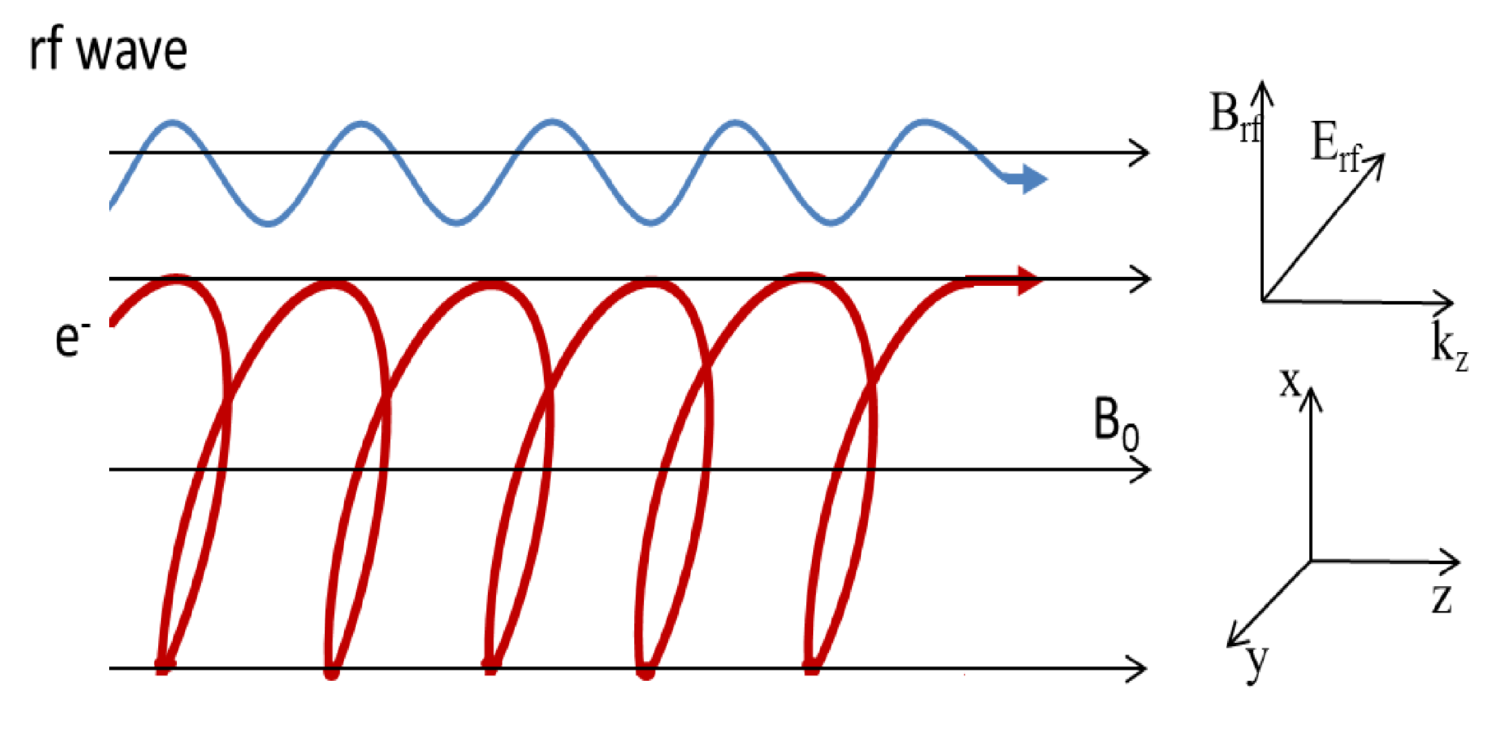
The key elements to understand the CARM FEL dynamics are sketched out in
Figure 6, which displays a moderately relativistic e-beam, with a relativistic factor
, moving inside the waveguide of a resonant cavity, along an axial static magnetic field
, executing helical trajectories with a period
where
, the cyclotron relativistic frequency.
The “behavioural” paradigm of CARM is the same as for any free electron radiation generator, namely, the electrons are expected to lose energy in favor of a selected operating mode, if appropriate matching conditions are satisfied. The way in which the energy exchange occurs is traced back to the standard mechanisms of the e-beam energy modulation and bunching. The last effect is characterized by transverse and longitudinal contributions.
Going back to
Figure 6, we note that the underlying dynamics can be described as follows. The electrons with longitudinal velocity
are propagating in a longitudinal magnetic field in the presence of a co-propagating electromagnetic field characterized by a wavevector
which in terms of frequency and phase velocity (
) reads
We can now establish an analogy between CARM and magnetic undulator FEL (U-FEL) using only kinematics arguments.
The electron velocity inside the cavity is specified by its longitudinal and vertical components, linked to the relativistic factor by
and
The electron and the radiation move, inside the cavity, at different speeds. We expect that after each helical path the following slippage is accumulated
This is the phase advance of the electromagnetic wave after each helical path with respect to the electrons. Constructive interference of the wavefront of the emitted radiation at the next period is ensured if
with
being the wavelength of the field propagating with the electrons. Putting together Equations (
9), (
14) and (
11), we end up with the matching condition.
The transverse component of the velocity is the key parameter allowing the coupling with the wave transverse field. In terms of the analogy we are suggesting it plays the same role as the undulator strength parameter being .
In the relativistic regime and assuming that
Equation (
13) reduces to
where the trajectory helical path is understood to play the same role of the undulator period (for further comments see [
18,
34]).
The Equation (
15), derived under the assumption of (ultra) relativistic regime, provides a brief idea of how CARM and U-FEL can be viewed within a common framework. In the following we will develop a more appropriate treatment valid for the nonrelativistic regime.
The discussion might be misleading if not properly commented. Therefore, we underscore that the interaction occurs in a waveguide, whose dispersion relation needs to be included to derive the matching conditions, specifying the CARM operating wavelength. The interaction can be viewed as an intra waveguide Compton backscattering, the associated frequency up-shift is written as
and the matching to the waveguide conditions is ensured by the coupling with the dispersion relation
where
s and
are the harmonic index and cutoff frequency (see below), respectively.
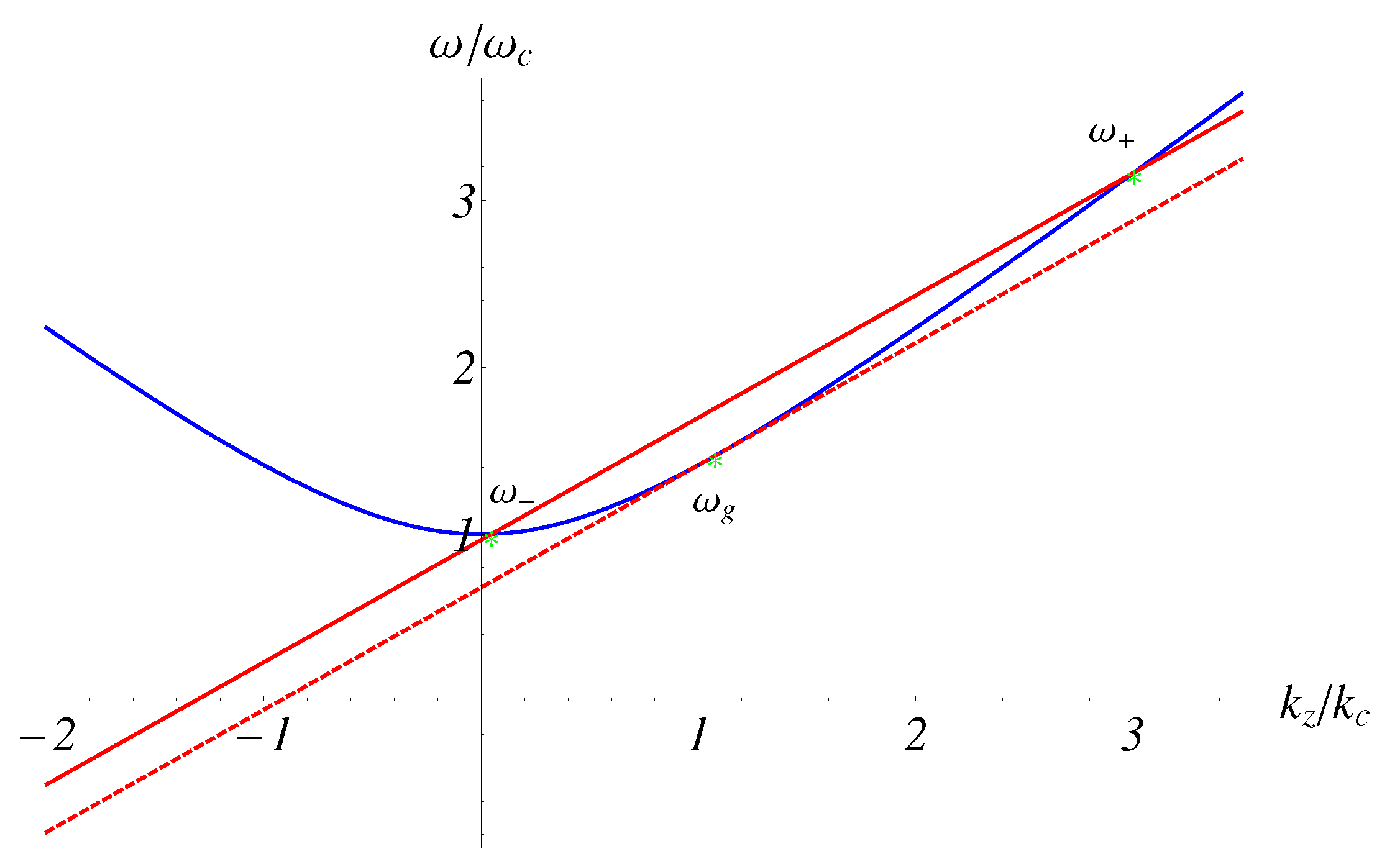
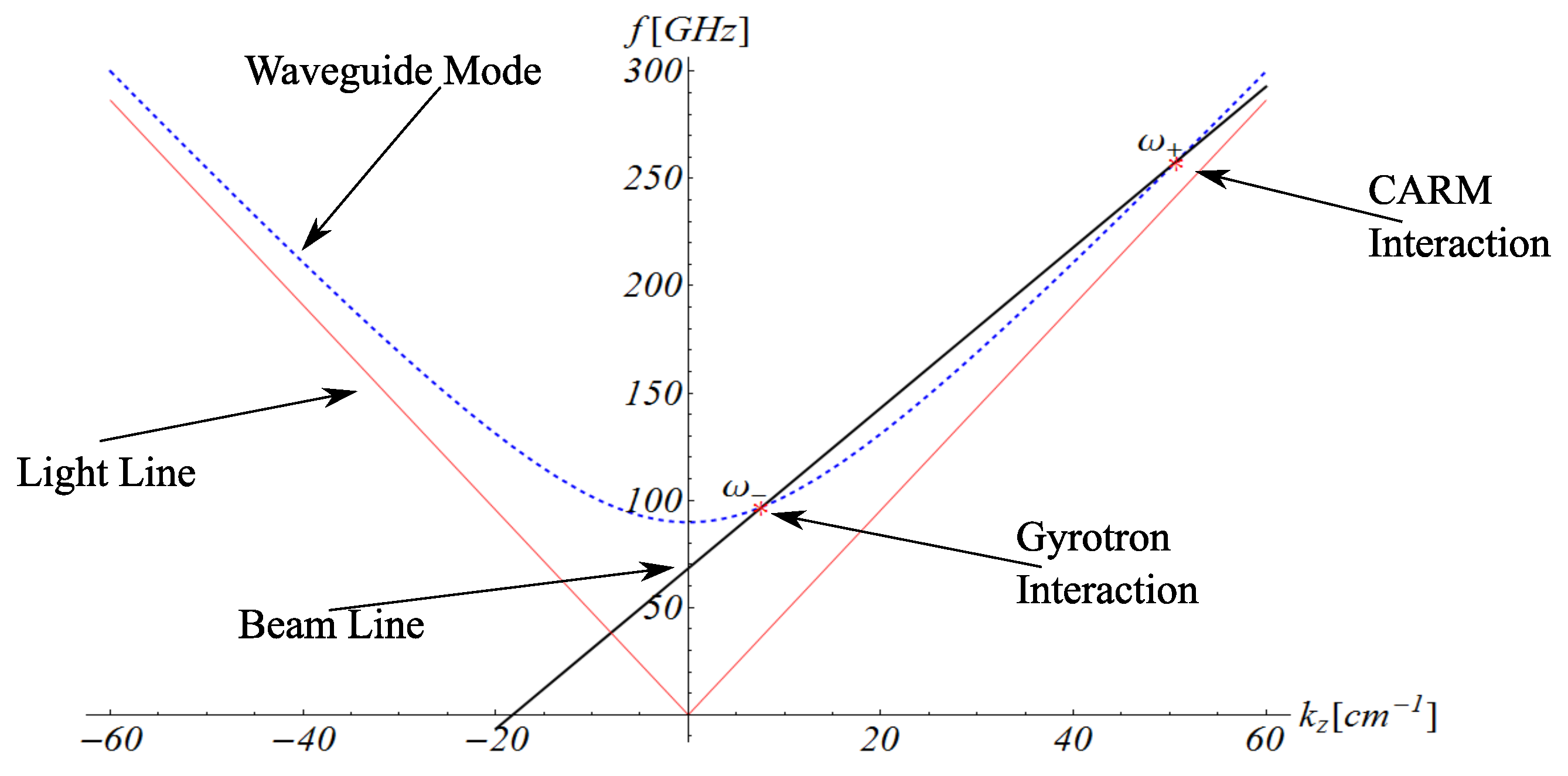
Unlike the free space FEL, the intersection between the curves of Equations (
16) and (
17) admits (see
Figure 7, for a geometric interpretation in the Brillouin
space) two solutions, corresponding to gyrotron (lower frequency) and CARM (higher frequency) operations modes
being
The cutoff frequency in Equation (
18) (
) is defined in terms of the eigenvalues
of the wavenumber characterizing the
mode excited by the FEL CARM interaction. The relevant physical role is that of controlling the “nature” of the roots in Equations (
18), determined by the intersection of the curves of Equations (
16) and (
17).
The “wave parameter” is lower than 1, in order to ensure two distinct intersections and is assumed to be greater than , to avoid a backward wave root.
Before introducing more specific details, let us further comment on the presence of both gyrotron and CARM modes. This is a distinctive feature with respect to the magnetic undulator configuration. In principle, both modes have a chance to grow. Particular care should therefore be devoted to the suppression of the counterpart.
The theoretical analysis of CARM has been developed in the past in a number of authoritative papers [
32,
33,
35,
36,
37,
38,
39,
40,
41] and will not be reported here. We note simply that the set of equations ruling the CARM interaction, even though characterized by a more complicated phenomenology than the ordinary magnetic FEL, can be viewed in a way not dissimilar from the pendulum-like equations, adopted in the description of FEL undulator devices.
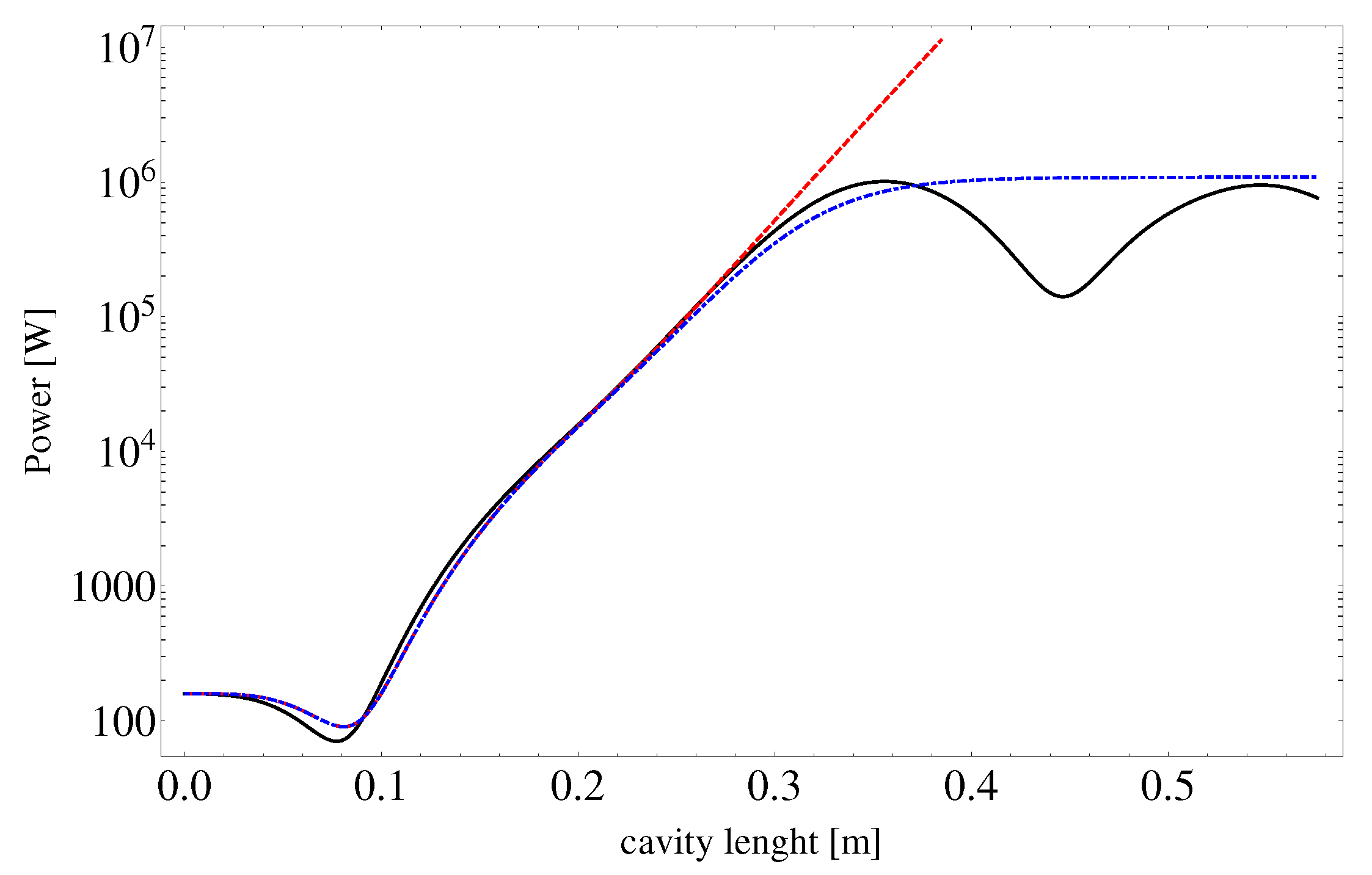
In
Figure 8 we report the growth of the CARM power for the set of parameters specified in the caption. We have included a comparison with the (analytical) small signal approximation (SSA), obtained in [
42].
The power growth exhibits the same S-shaped logistic behavior of high-gain SASE FEL devices (see the superimposed dot-dashed curve), which is analytically reproduced (till the onset of the saturation) by
where
with
being the analytical linear solution of the growth signal,
—the input signal power and
the final CARM power given by
being
the efficiency of the device, which will be commented on later in this section.
The inspection of
Figure 8 confirms that the power growth consists of three distinct phases:
- (a)
lethargy, where the system organizes coherence;
- (b)
linear regime;
- (c)
saturation.
We consider in the following a specific configuration of parameters (see
Table 1) capable of providing sufficiently large power in the region below
mm wavelength. In
Figure 9 we show the frequency selection on the Brillouin diagram. The chosen parameters realize the CARM interaction in a region with
allowing to select the operating mode without exciting the parasitic modes, and with
by the use of a moderately relativistic beam.
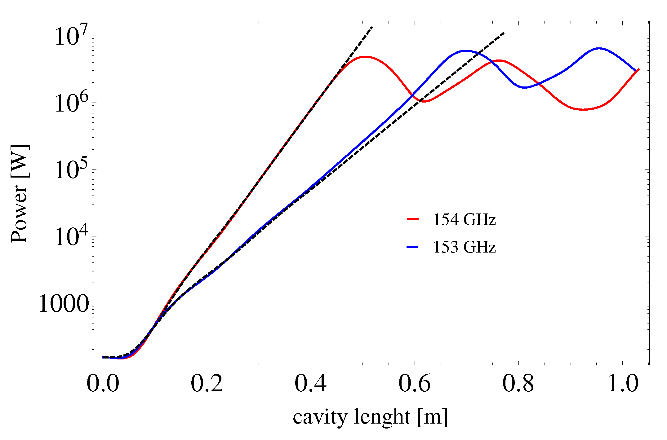
Figure 10 shows the associated power growth for two frequencies (153–154) GHz close to the CARM resonance (
), which displays a maximum output power of 4.8–6.4 MW and thus an efficiency of 19–25%, respectively.
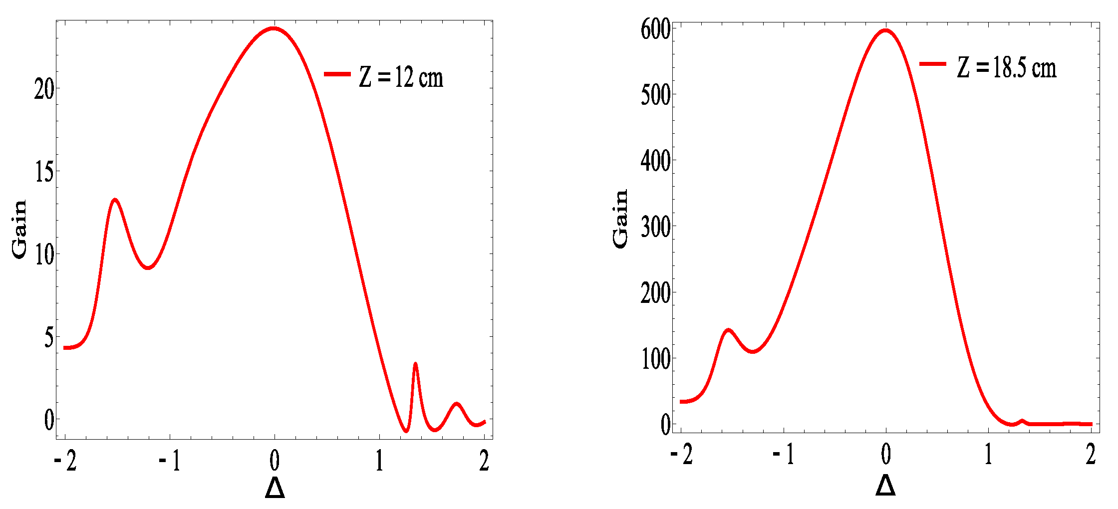
The linear regime is characterized by the small signal gain, which exhibits, along the longitudinal coordinate the transition from low- to high-gain regime, displayed in
Figure 11. The gain curve vs. the normalized detuning
,
where
and
, exhibiting the characteristic bell-shaped form.
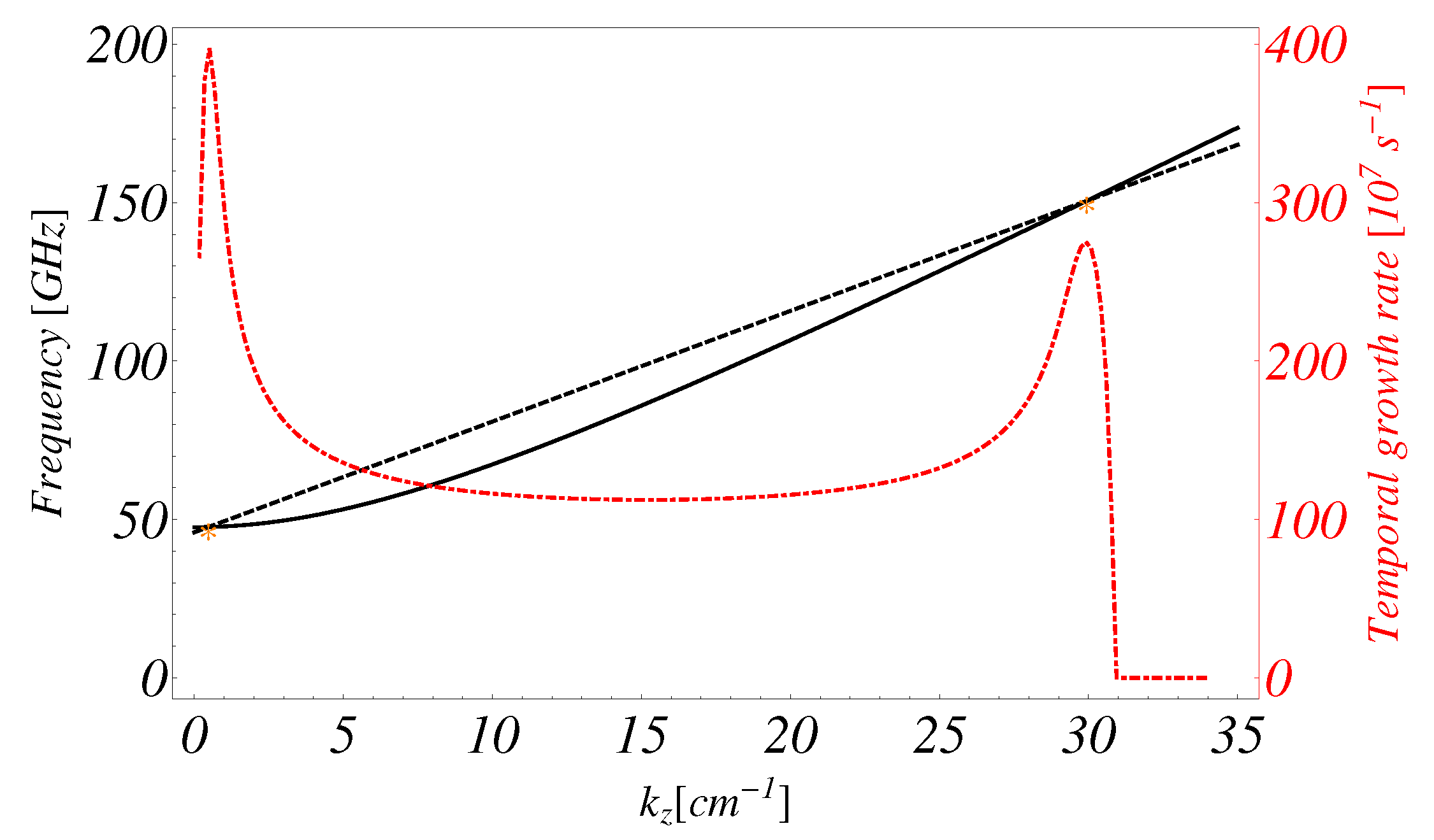
Before concluding this section, we would like to clarify two points we have just touched on. We mention that the gyrotron mode may grow too. In
Figure 12 we report the temporal growth rate vs. the wave vector
, using the parameters reported in
Table 1, exploring the two resonances at
and
.
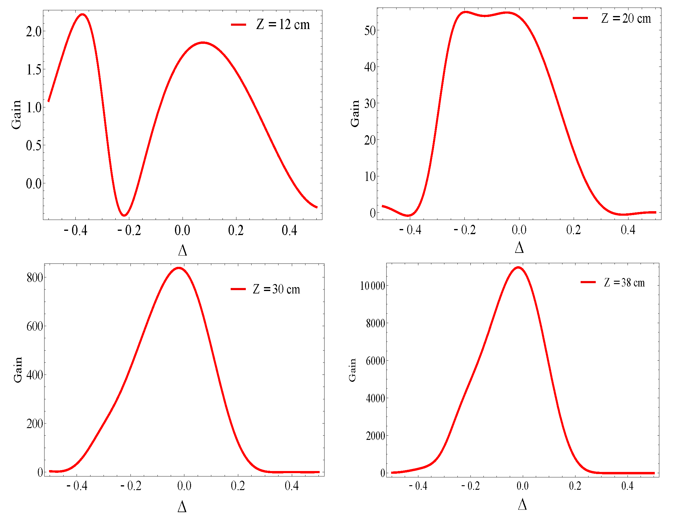
In
Figure 13, we report the low-frequency mode
, at different z-values inside the waveguide. The gain is significantly larger and could be dominant with respect to the CARM mode. The associated power growth can be suppressed by suitably seeding the up-shifted mode.
The second point concerns the evaluation of the CARM efficiency, which, unlike the magnetic case is significantly larger and reaches values around tens of percent. The reasons underlying these large values are the characteristic feature of the device itself. The interaction occurs in such a way that the gain curve is larger and the interaction is resonant for a longer time [
33] thus following a behavior not dissimilar by tapered FEL device [
43].
3. CARM, RFU and VUV Soft X-ray FEL Operation
In the introductory section of this paper, we set out the general conditions to be fulfilled by a RF wave in the millimeter region, to sustain the operation of a RFU. The requirements in terms of power, power density, wavelength...of the RF field ensuring a FEL SASE operation have shown some criticalities, which relax with increasing FEL wavelength.
The conclusions we have drawn apply to any RF device (Gyrotron, Gyro-klystron, Magnetron, etc.) CARM is suited to operate in the region above 100 GHz mm, where the other sources exhibit a breakdown in terms of maximum achievable power. We will therefore discuss a few specific issues for the use of 1–3 mm CARM-RFU.
In the introductory section, we have a RF power density larger than
W/m
in order to achieve values of the strength parameter (
see
Figure 2b) not far from unity (the subscript
w has been replaced by
to underscore that it refers to radio frequency intensity). The CARM power, namely, the amount of power transferred from the electron beam to the RF field, is expected to be about
MW, which should accordingly be transported along a pipe with a radius
m, small to transport radiation in the microwave range and for any realistic mechanical handling.
In
Figure 14, we have reported the electron beam energy, the electron beam current density, the electron beam transverse section and the peak current vs. the RF wavelength, assuming a significantly reduced value of the RFU power density
and FEL wavelengths in the VUV-X range
nm.
We should underscore that, even with these relaxed numbers, it is not an easy task to transport this amount of power density. In order to enhance the RF power density we can proceed by increasing CARM output power, using, e.g., a suitable compression of the associated pulse.
We remind that the CARM is driven by an e-beam sustained by a pulse forming system, with a flat top of the order of microseconds [
44]. The RF pulse has accordingly a comparable length. The power can be enhanced by compressing the pulse, by reducing it to a length comparable with the saturation length, namely tens of ns.
According to the previous discussion, the CARM pulse compression to a duration of tens of ns (few meters, approximately the saturation length foreseen for RFU operation) is sufficient to ensure CARM peak power level near the GW level.
The possibility of achieving these results has been suggested in refs. [
45,
46], in which the use of a dispersive corrugated metal waveguide was proposed. The crucial idea put forward in these articles is that of exploiting a swept frequency modulated train of pulses that propagate inside the waveguide, with a monotonically increasing group velocity. Accordingly, the tail of the pulse will overtake its head, thus providing either a shortening of its duration and an increase (in absence of significant losses) of the relevant amplitude.
Most of the compression process occurs at the end of the waveguide, where all the frequency components are present at the same time and the compression ratio (
C) can be expressed as [
46]
being
, with
the group velocities at the beginning and at the end frequencies of the RF pulse,
—the fractional bandwidth,
L—the waveguide length,
—the CARM wavelength and
—the waveguide losses. The compression factor, summarized by Equation (
23), is one of the central point of the discussion. It requires a careful design of the radiation transport in the corrugated waveguide, that follows the “active” waveguide where the CARM amplification and growth occurs. The physical mechanism beyond Equation (
23) is fairly straightforward; the helically corrugated waveguide is designed with a dispersion relation ensuring a significant dependence of the group velocity on the frequency, accordingly, if a pulse is modulated from one frequency to a frequency with a higher group velocity the pulse will be compressed. The simulations and the experimental results of the aforementioned paper [
46,
47] report compression ratios around 25, for tens of GHz RF with a bandwidth of 5%. In accordance with our simulation the bandwidth of the RF generated by the CARM amplifier is sufficiently large (around 5.3%), and can be be eventually increased by using an input seed in the CARM cavity with larger bandwidth in order to compensate any major losses in the compression factor. Finally, the cavity length must be adjusted to contain the highest flat power of the signal to be compressed. This could be a limitation for the pulse length which in principle cannot be more than hundreds of ns for a reasonable cavity length (a couple of meters assuming a group velocity value 1/10 of light speed). A long CARM RF pulse (
s) can be also used by modulating the input signal in the CARM cavity in order to produce a conveniently chopped signal.
According to our preliminary calculations, we can foresee an analogous behavior for RF CARM around 150 GHz; we have been conservative regarding the maximum CARM output power and we would like to underscore that even a factor two larger is within the realm of the present technology.
Considering a reduction of the pulse duration by two orders of magnitude and assuming a power loss of we can foresee an amount of power, available for wave-undulator operation, 250 MW. The required power density is accordingly obtained by confining the RFU over a surface of mm radius (reasonably large to transport radiation in the wavelength region of our interest).
The next step is to specify how the RF transport cavity should be designed.
The conclusion we may draw, from the inspection of the plots, is that the CARM RFU FEL is conceivable, at least in the soft X-ray region. The RFU power should be confined over a small surface to ensure the required density power level, warranting values suitable for FEL SASE operation.
The following analysis is limited to RF wavelength within 1–3 mm. The requests on the electron beam are not particularly challenging, with respect to those of the RFU power transport waveguide, which according to the prescription of ref. [
24] requires the selection of
modes combination, characterized by a small transverse section, ensuring the required large intensity.
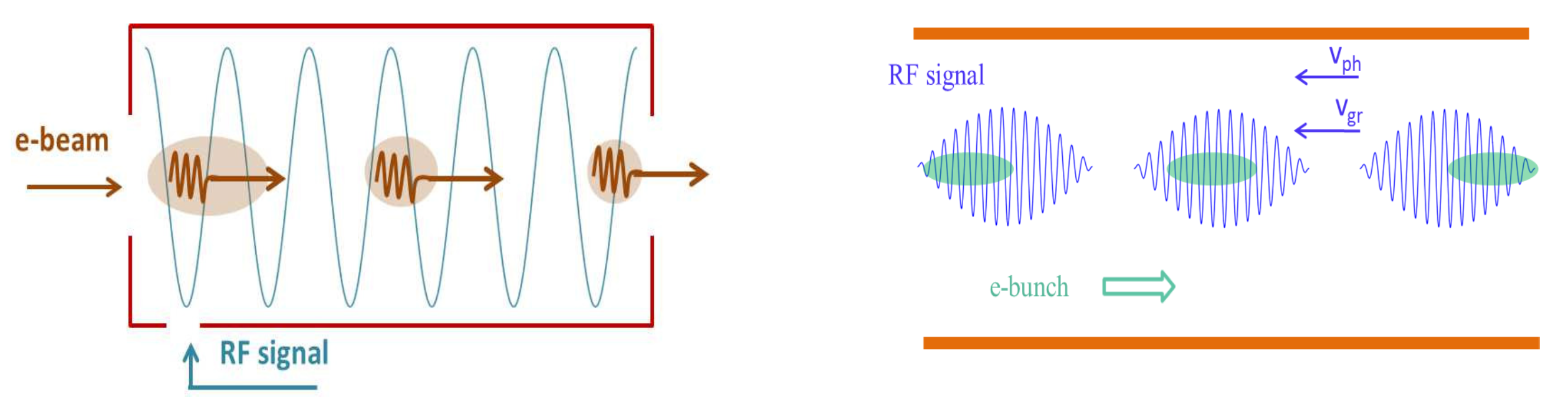
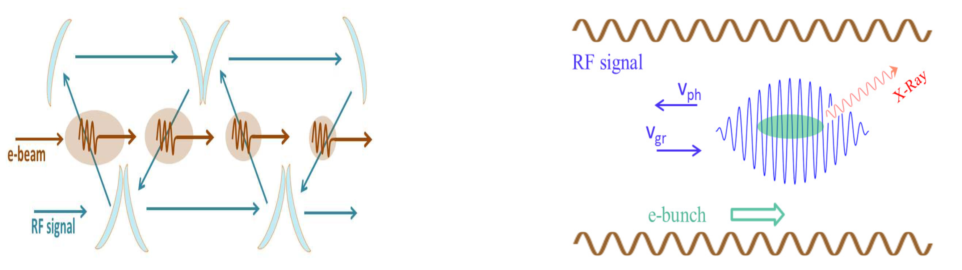
Regarding the electron–radiation interaction schemes, several solutions have been foreseen, as illustrated in
Figure 15 where the “standard” RFU standing wave undulator is reported on the left, while the flying undulator concepts on the right with phase and group velocity are directed in the opposite electron direction.
There is a natural drawback affecting the counter propagating scheme, namely the effective interaction length. If the RF wave propagates inside the guide with group velocity
and if the RFU pulse has a duration
, the effective interaction length is [
24]
for
. In other words, the effective length becomes a factor two lower than the pulse length itself, which means only half of the undulator is exploited. On the other side, the “co-propagating” scheme in
Figure 16 (left) does not suffer the same problem. The cavity is indeed designed with corrugated helical ripples [
24] which allow the pulse train to move with group velocity pointing in the same direction of the electrons and the phase velocity opposite. The effective interaction length is therefore
greater than the head-on case by a factor
.
It might be thought that for the co-propagating scheme, the Compton backscattering up-shift does not occur. This is not true because the waveguide structure ensures the up-shift, according to what is shown in
Figure 16 (right) where the effective intra-guide RF propagation is displayed. The radiation follows a kind of reflection, at each ripple, allowing multiple reflections pushing its “center of mass” in the forward direction. The head-on interaction occurs in the region where electrons and radiation overlaps (brown disk in
Figure 16 (left)).
The use of a standing wave backscattering configuration is, however, feasible, at the price of operating the device with a longer waveguide.
Both configurations require the necessity of a pulse compression and the transport through a waveguide supporting hybrid mode structures, whose detailed design will be presented elsewhere. The solution foreseen in
Figure 16 seems to be more appealing for the architecture we consider.
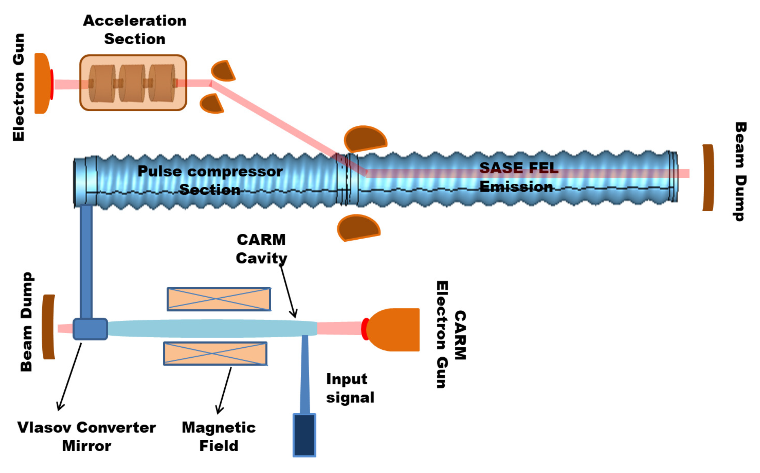
In
Figure 17 we report a sketch of the whole device, indicating the RF CARM injected inside the corrugated waveguide (with a mode converter/mirror) and after the compression delivered in the second corrugated waveguide where the FEL SASE interaction occurs.
In this paper, we consider the possibility of operating a FEL SASE device using a RFU pumped by a CARM device. The microwave CARM is a nearly mature technology, useful to develop “compact” FELs operating in the VUV and soft X-ray region. The intrinsic limitations of these devices are, as previously underscored, associated with the maximum CARM available power (limiting the strength parameter) and with the physical dimensions of the radiation transport vacuum pipe radius, limiting the cutoff frequency of the propagated radiation. The combination of these two limiting factors has indicated a threshold of 10 nm as the minimum operating wavelength. It should furthermore be stressed that, although we have indicated a pulse compression method as a useful device to enhance the microwave power, we did not underscore enough that it is still at the level of experimental studies, not yet conducted in the frequency range above 100 GHz. This solution, if viable, would provide a real step towards the realization of compact X-ray FEL devices. The construction of this type of short FEL wavelength device is a challenging promising task, which foresees the use and merging of high-level technologies, within the present or next future capabilities.


 ,
, 


