
A Novel Laser-Aided Machining and Polishing Process for Additive Manufacturing Materials with Multiple Endmill Emulating Scan Patterns


Abstract
:1. Introduction
2. Materials and Methods
2.1. Materials
2.2. Methodology
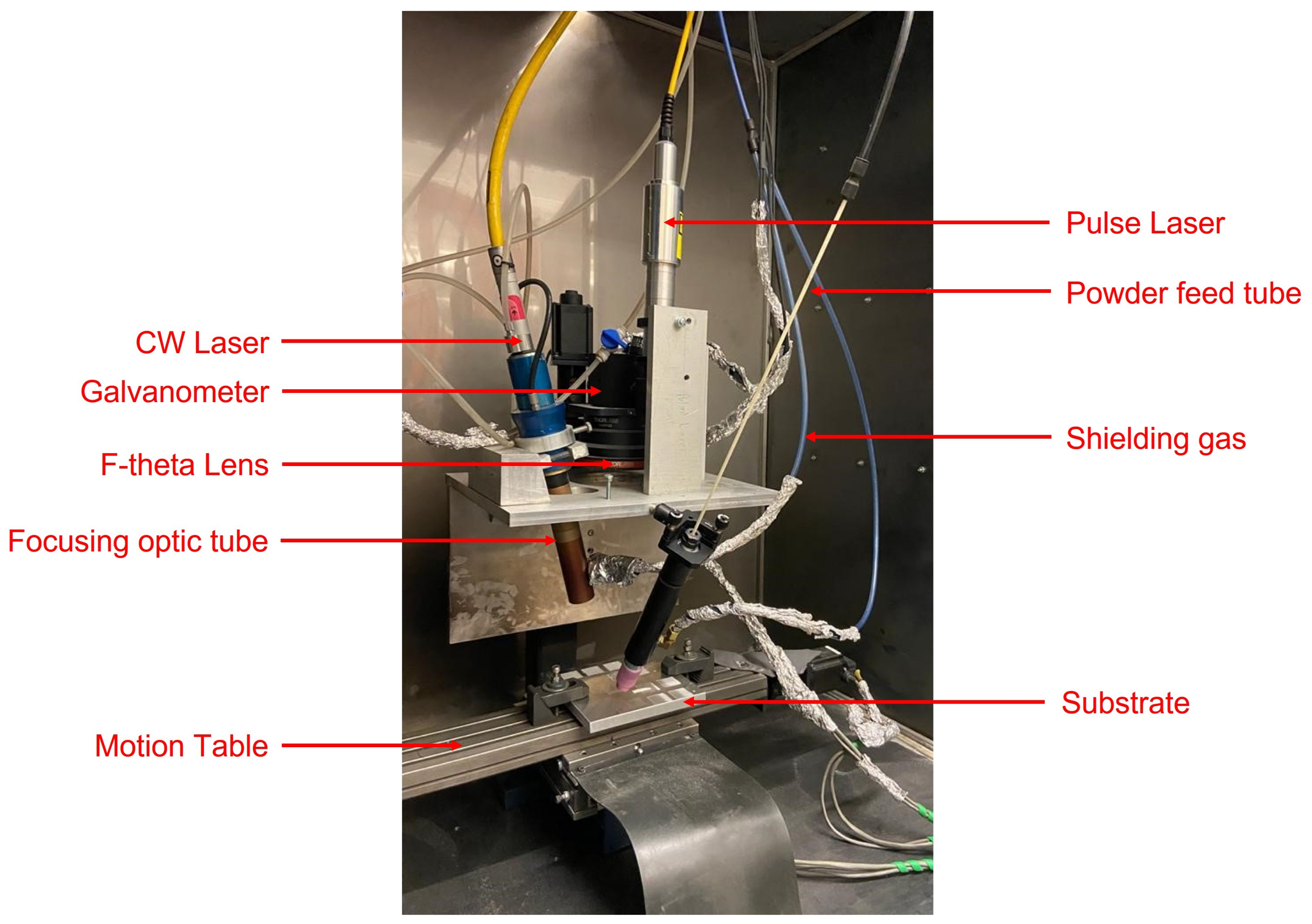
2.2.1. Experimental Setup
2.2.2. Fabrication
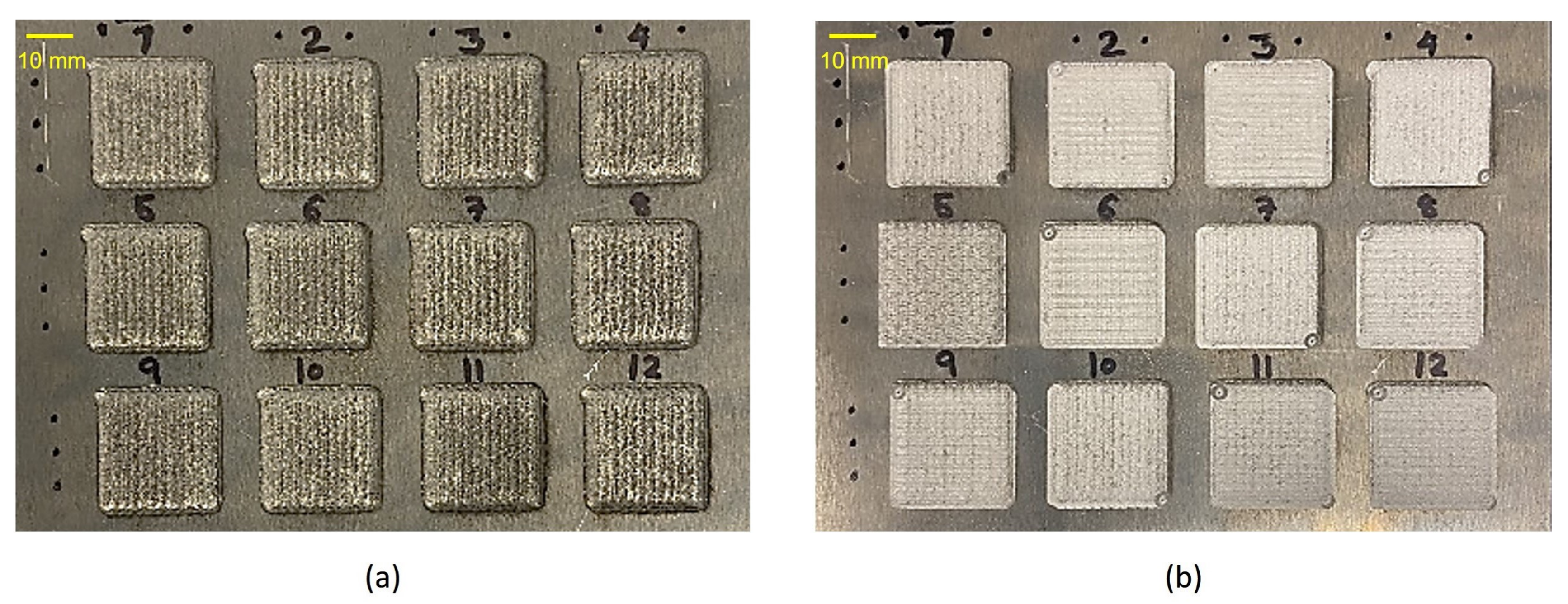
2.2.3. Machining
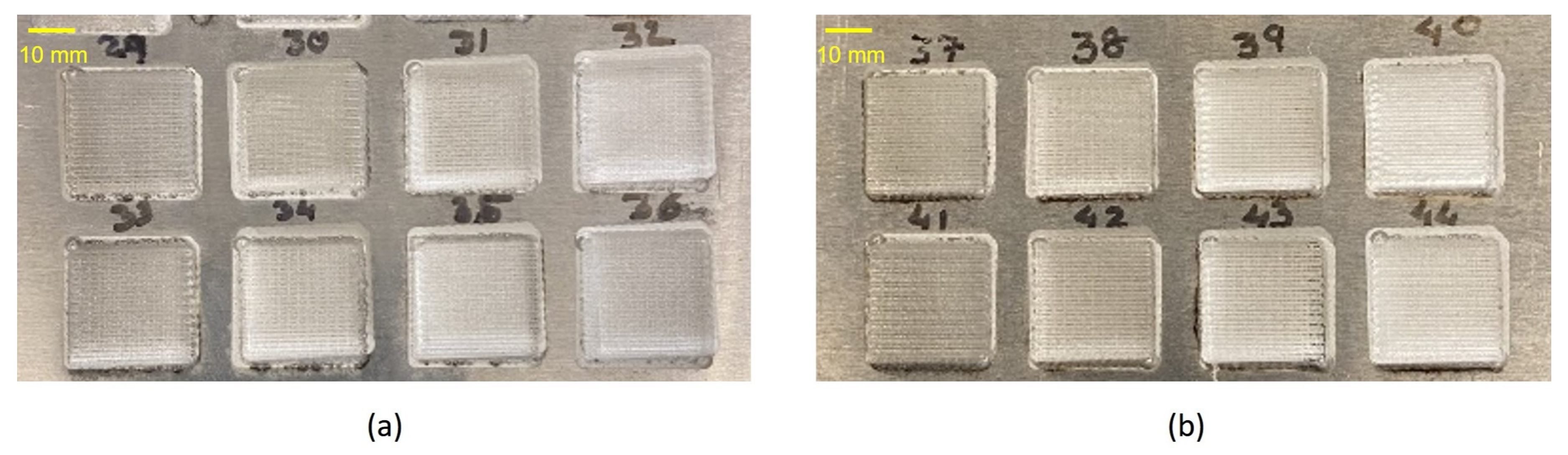
2.2.4. Polishing
2.3. Surface Roughness Measurement
3. Results and Discussion
4. Conclusions
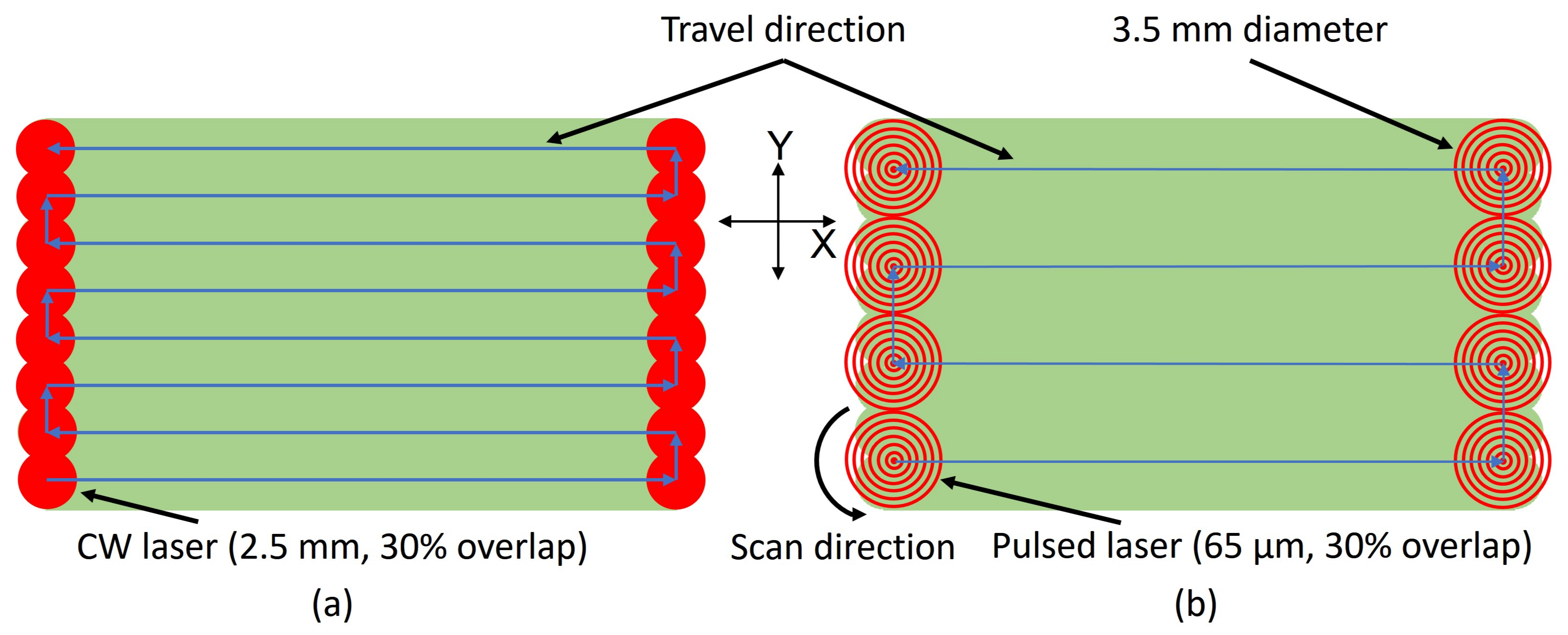
- In this study, multiple lasers were integrated for fabrication, machining, and polishing of AM materials in the same build chamber. A unique scan pattern was also introduced to implement low energy input for machining and polishing of metals. A two-step polishing process using CW and pulsed laser was employed for rough and fine polishing.
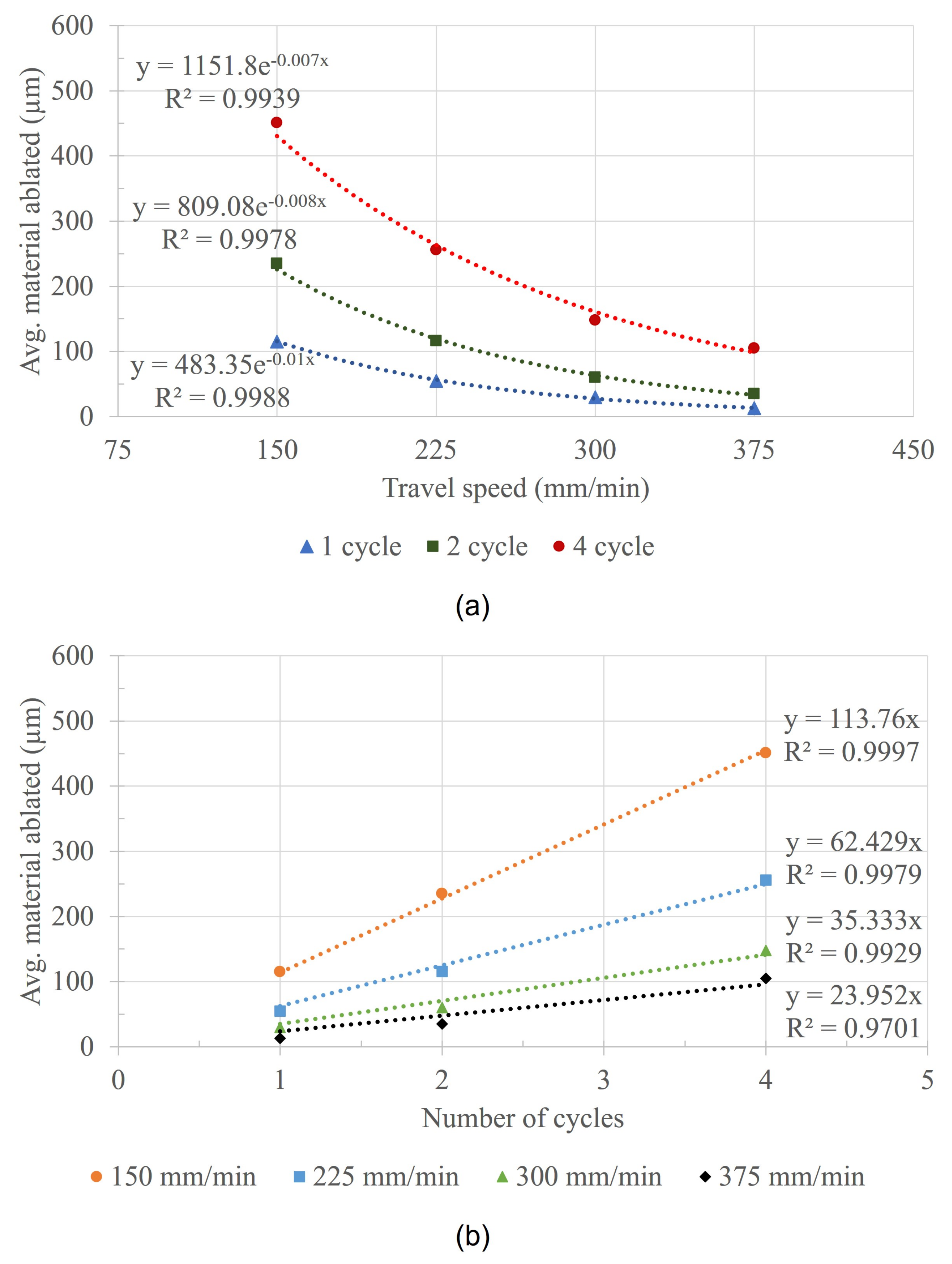
- A systematic approach was discussed and implemented to obtain optimal process parameters for machining and polishing of AM aluminum alloy. A regression analysis was performed, and a mathematical model was derived from the experimental results to predict the material removed during the machining process.
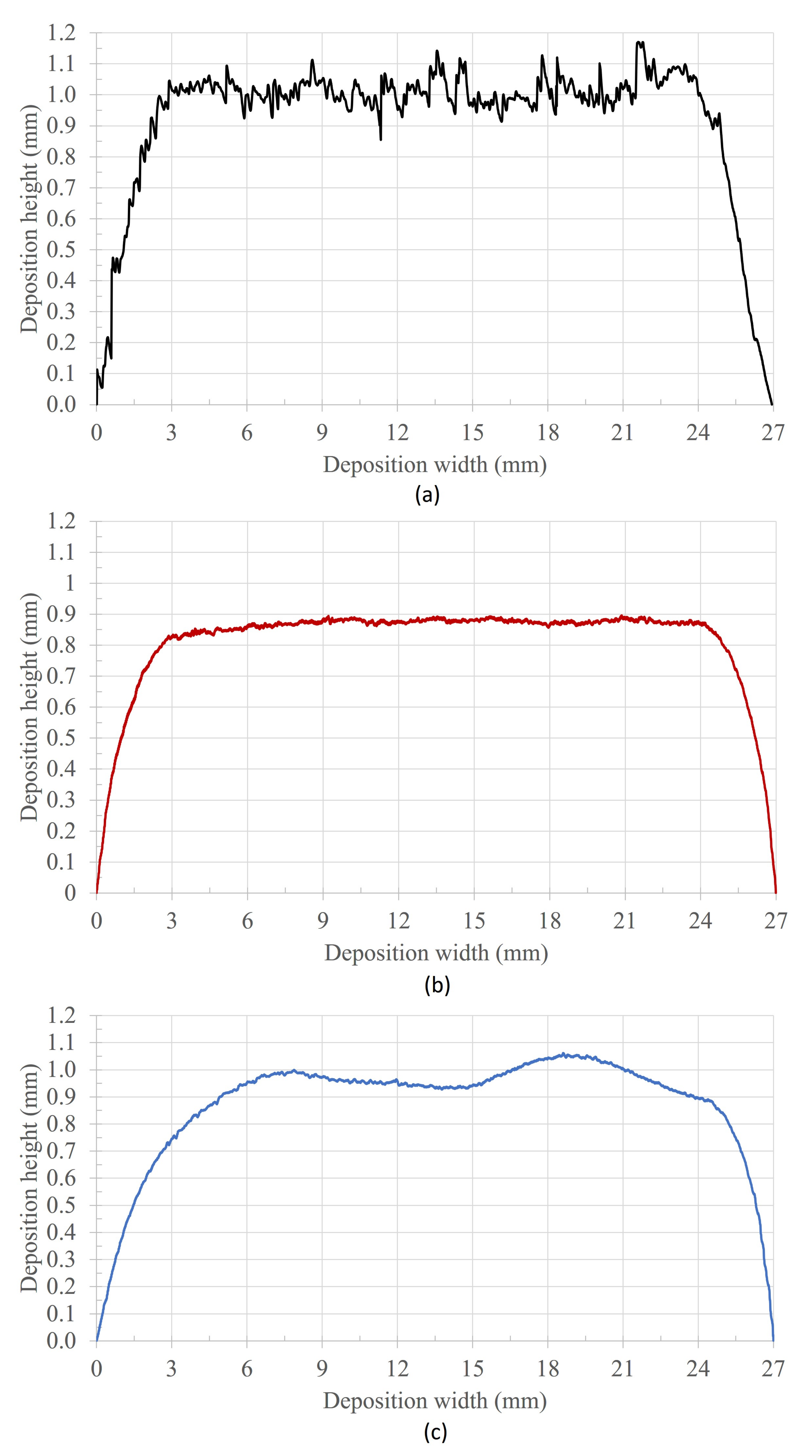
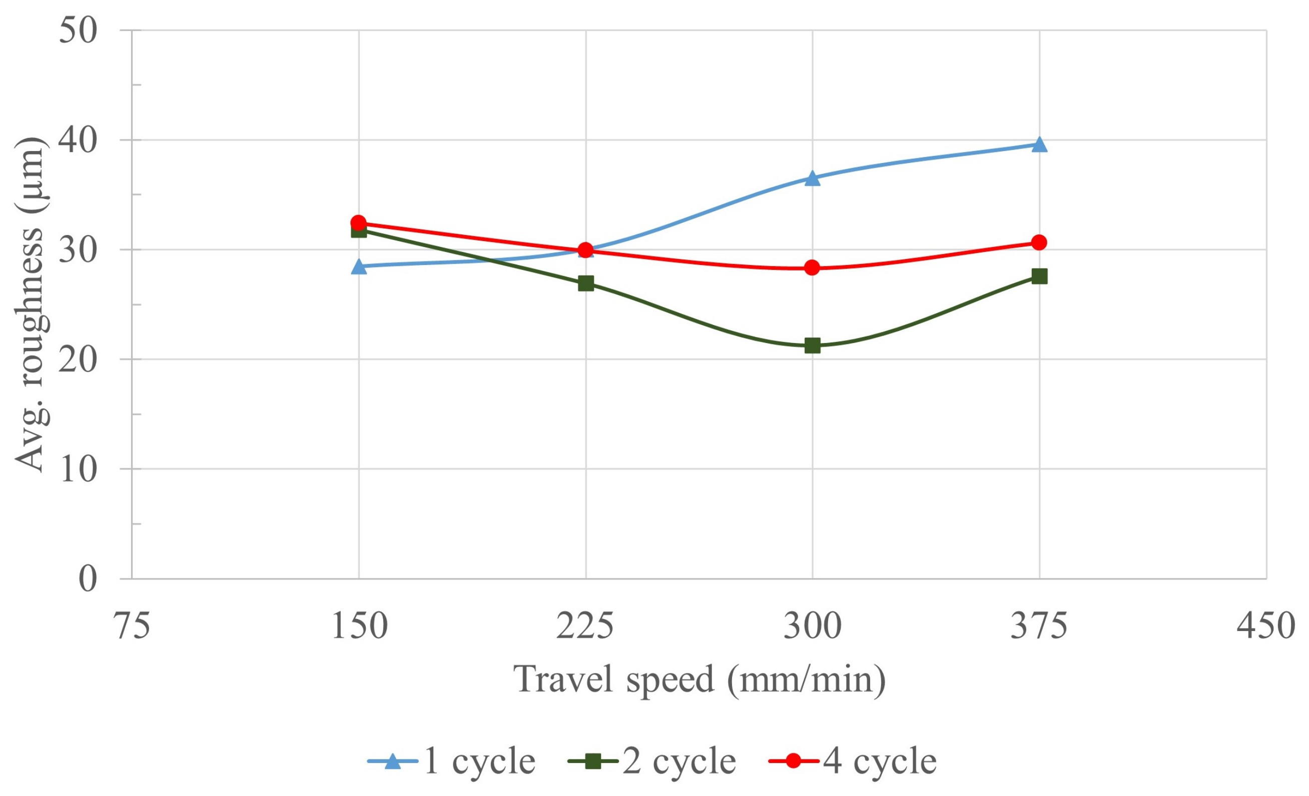
- The roughness and waviness in the surface topography were minimized using the combined machining and polishing process and a more than 97% improvement in surface quality was achieved.
Author Contributions
Funding
Conflicts of Interest
References
- Zhang, Y.; Wu, L.; Guo, X.; Kane, S.; Deng, Y.; Jung, Y.G.; Lee, J.H.; Zhang, J. Additive manufacturing of metallic materials: A review. J. Mater. Eng. Perform. 2018, 27, 1–13. [Google Scholar] [CrossRef] [Green Version]
- Frazier, W.E. Metal additive manufacturing: A review. J. Mater. Eng. Perform. 2014, 23, 1917–1928. [Google Scholar] [CrossRef]
- Lewandowski, J.J.; Seifi, M. Metal additive manufacturing: A review of mechanical properties. Annu. Rev. Mater. Res. 2016, 46, 151–186. [Google Scholar] [CrossRef] [Green Version]
- Gibson, I.; Rosen, D.; Stucker, B.; Khorasani, M. Design for additive manufacturing. In Additive Manufacturing Technologies; Springer: Berlin/Heidelberg, Germany, 2021; pp. 555–607. [Google Scholar]
- Wong, K.V.; Hernandez, A. A review of additive manufacturing. Int. Sch. Res. Not. 2012, 2012, 208760. [Google Scholar] [CrossRef] [Green Version]
- Parvez, M.; Chen, Y.; Newkirk, J.; Liou, F. Comparison of fatigue performance between additively manufactured and wrought 304L stainless steel using a novel fatigue test setup. In Proceedings of the Solid Freeform Fabrication, Austin, TX, USA, 12–14 August 2019; pp. 353–363. [Google Scholar]
- Ramos-Grez, J.; Bourell, D. Reducing surface roughness of metallic freeform-fabricated parts using non-tactile finishing methods. Int. J. Mater. Prod. Technol. 2004, 21, 297–316. [Google Scholar] [CrossRef]
- Abele, E.; Kniepkamp, M. Analysis and optimisation of vertical surface roughness in micro selective laser melting. Surf. Topogr. Metrol. Prop. 2015, 3, 034007. [Google Scholar] [CrossRef]
- Calignano, F.; Manfredi, D.; Ambrosio, E.; Iuliano, L.; Fino, P. Influence of process parameters on surface roughness of aluminum parts produced by DMLS. Int. J. Adv. Manuf. Technol. 2013, 67, 2743–2751. [Google Scholar] [CrossRef] [Green Version]
- Parvez, M.M.; Pan, T.; Chen, Y.; Karnati, S.; Newkirk, J.W.; Liou, F. High Cycle Fatigue Performance of LPBF 304L Stainless Steel at Nominal and Optimized Parameters. Materials 2020, 13, 1591. [Google Scholar] [CrossRef] [Green Version]
- Mills, K.; Keene, B.; Brooks, R.; Shirali, A. Marangoni effects in welding. Philos. Trans. R. Soc. Lond. Ser. A Math. Phys. Eng. Sci. 1998, 356, 911–925. [Google Scholar] [CrossRef]
- Cho, M.H.; Farson, D.F. Understanding bead hump formation in gas metal arc welding using a numerical simulation. Metall. Mater. Trans. B 2007, 38, 305–319. [Google Scholar] [CrossRef]
- Hauser, C.; Childs, T.; Dalgamo, K. Selective laser sintering of stainless steel 314S HC processed using room temperature powder beds. In Proceedings of the Solid Freeform Fabrication, Austin, TX, USA, 11–13 August 1999. [Google Scholar]
- Klocke, F.; Wagner, C. Coalescence behaviour of two metallic particles as base mechanism of selective laser sintering. CIRP Ann. 2003, 52, 177–180. [Google Scholar] [CrossRef]
- Li, R.; Liu, J.; Shi, Y.; Wang, L.; Jiang, W. Balling behavior of stainless steel and nickel powder during selective laser melting process. Int. J. Adv. Manuf. Technol. 2012, 59, 1025–1035. [Google Scholar] [CrossRef]
- Kruth, J.P.; Vandenbroucke, B.; Van Vaerenbergh, J.; Mercelis, P. Benchmarking of different SLS/SLM processes as rapid manufacturing techniques. In Proceedings of the International Conference Polymers & Moulds Innovations PMI 2005, Gent, Belgium, 20–23 April 2005. [Google Scholar]
- Mumtaz, K.; Hopkinson, N. Top surface and side roughness of Inconel 625 parts processed using selective laser melting. Rapid Prototyp. J. 2009, 15, 96–103. [Google Scholar] [CrossRef]
- Strano, G.; Hao, L.; Everson, R.M.; Evans, K.E. Surface roughness analysis, modelling and prediction in selective laser melting. J. Mater. Process. Technol. 2013, 213, 589–597. [Google Scholar] [CrossRef]
- Vilar, R.M. Laser cladding. In Proceedings of the ALT’02 International Conference on Advanced Laser Technologies. International Society for Optics and Photonics, Adelboden, Switzerland, 16–20 September 2002; Volume 5147, pp. 385–392. [Google Scholar]
- Parvez, M.M.; Chen, Y.; Karnati, S.; Coward, C.; Newkirk, J.W.; Liou, F. A Displacement Controlled Fatigue Test Method for Additively Manufactured Materials. Appl. Sci. 2019, 9, 3226. [Google Scholar] [CrossRef] [Green Version]
- Spierings, A.B.; Starr, T.L.; Wegener, K. Fatigue performance of additive manufactured metallic parts. Rapid Prototyp. J. 2013, 19, 88–94. [Google Scholar] [CrossRef]
- Taminger, K.; Hafley, R.A.; Fahringer, D.T.; Martin, R.E. Effect of surface treatments on electron beam freeform fabricated aluminum structures. In Proceedings of the Solid Freeform Fabrication, Austin, TX, USA, 11–13 August 2004. [Google Scholar]
- Löber, L.; Flache, C.; Petters, R.; Kühn, U.; Eckert, J. Comparison of different post processing technologies for SLM generated 316l steel parts. Rapid Prototyp. J. 2013, 19, 173–179. [Google Scholar] [CrossRef]
- Beaucamp, A.T.; Namba, Y.; Charlton, P.; Jain, S.; Graziano, A.A. Finishing of additively manufactured titanium alloy by shape adaptive grinding (SAG). Surf. Topogr. Metrol. Prop. 2015, 3, 024001. [Google Scholar] [CrossRef]
- Flynn, J.M.; Shokrani, A.; Newman, S.T.; Dhokia, V. Hybrid additive and subtractive machine tools–Research and industrial developments. Int. J. Mach. Tools Manuf. 2016, 101, 79–101. [Google Scholar] [CrossRef] [Green Version]
- Ermergen, T.; Taylan, F. Review on Surface Quality Improvement of Additively Manufactured Metals by Laser Polishing. Arab. J. Sci. Eng. 2021, 46, 7125–7141. [Google Scholar] [CrossRef]
- Krishnan, A.; Fang, F. Review on mechanism and process of surface polishing using lasers. Front. Mech. Eng. 2019, 14, 299–319. [Google Scholar] [CrossRef] [Green Version]
- Deng, T.; Li, J.; Zheng, Z. Fundamental aspects and recent developments in metal surface polishing with energy beam irradiation. Int. J. Mach. Tools Manuf. 2020, 148, 103472. [Google Scholar] [CrossRef]
- Giorleo, L.; Ceretti, E.; Giardini, C. Ti surface laser polishing: Effect of laser path and assist gas. Procedia Cirp 2015, 33, 446–451. [Google Scholar] [CrossRef] [Green Version]
- Bordatchev, E.V.; Hafiz, A.M.; Tutunea-Fatan, O.R. Performance of laser polishing in finishing of metallic surfaces. Int. J. Adv. Manuf. Technol. 2014, 73, 35–52. [Google Scholar] [CrossRef] [Green Version]
- Mohajerani, S.; Bordatchev, E.V.; Tutunea-Fatan, O.R. Recent developments in modeling of laser polishing of metallic materials. Lasers Manuf. Mater. Process. 2018, 5, 395–429. [Google Scholar] [CrossRef]
- Marimuthu, S.; Triantaphyllou, A.; Antar, M.; Wimpenny, D.; Morton, H.; Beard, M. Laser polishing of selective laser melted components. Int. J. Mach. Tools Manuf. 2015, 95, 97–104. [Google Scholar] [CrossRef] [Green Version]
- Liang, C.; Hu, Y.; Liu, N.; Zou, X.; Wang, H.; Zhang, X.; Fu, Y.; Hu, J. Laser polishing of Ti6Al4V fabricated by selective laser melting. Metals 2020, 10, 191. [Google Scholar] [CrossRef] [Green Version]
- Lee, S.; Ahmadi, Z.; Pegues, J.W.; Mahjouri-Samani, M.; Shamsaei, N. Laser polishing for improving fatigue performance of additive manufactured Ti-6Al-4V parts. Opt. Laser Technol. 2021, 134, 106639. [Google Scholar] [CrossRef]
- Willenborg, E. Polishing with laser radiation. Kunststoffe Int. 2007, 97, 37. [Google Scholar]
- Perry, T.L.; Werschmoeller, D.; Li, X.; Pfefferkorn, F.E.; Duffie, N.A. Micromelting for laser micro polishing of meso/micro metallic components. In Proceedings of the International Manufacturing Science and Engineering Conference, Atlanta, GA, USA, 15–18 October 2007; Volume 42908, pp. 363–369. [Google Scholar]
- Wang, H.Y.; Bourell, D.; Beaman, J. Laser polishing of silica slotted rods. Mater. Sci. Technol. 2003, 19, 382–387. [Google Scholar] [CrossRef]
- Mohajerani, S.; Miller, J.D.; Tutunea-Fatan, O.R.; Bordatchev, E.V. Thermo-physical modelling of track width during laser polishing of H13 tool steel. Procedia Manuf. 2017, 10, 708–719. [Google Scholar] [CrossRef]
- Vatsya, S.; Nikumb, S. Modeling of fluid dynamical processes during pulsed-laser texturing of material surfaces. Phys. Rev. B 2003, 68, 035410. [Google Scholar] [CrossRef] [Green Version]
- Gora, W.S.; Tian, Y.; Cabo, A.P.; Ardron, M.; Maier, R.R.; Prangnell, P.; Weston, N.J.; Hand, D.P. Enhancing surface finish of additively manufactured titanium and cobalt chrome elements using laser based finishing. Phys. Procedia 2016, 83, 258–263. [Google Scholar] [CrossRef]
- Ćwikła, M.; Dziedzic, R.; Reiner, J. Influence of Overlap on Surface Quality in the Laser Polishing of 3D Printed Inconel 718 under the Effect of Air and Argon. Materials 2021, 14, 1479. [Google Scholar] [CrossRef]
- Zhang, D.; Yu, J.; Li, H.; Zhou, X.; Song, C.; Zhang, C.; Shen, S.; Liu, L.; Dai, C. Investigation of laser polishing of four selective laser melting alloy samples. Appl. Sci. 2020, 10, 760. [Google Scholar] [CrossRef] [Green Version]
- Lambarri, J.; Leunda, J.; Soriano, C.; Sanz, C. Laser surface smoothing of nickel-based superalloys. Phys. Procedia 2013, 41, 255–265. [Google Scholar] [CrossRef] [Green Version]
- Chen, L.; Zhang, X. Modification the surface quality and mechanical properties by laser polishing of Al/PLA part manufactured by fused deposition modeling. Appl. Surf. Sci. 2019, 492, 765–775. [Google Scholar] [CrossRef]
- Ma, C.; Vadali, M.; Duffie, N.A.; Pfefferkorn, F.E.; Li, X. Melt pool flow and surface evolution during pulsed laser micro polishing of Ti6Al4V. J. Manuf. Sci. Eng. 2013, 135, 061023. [Google Scholar] [CrossRef]
- Miller, J.D.; Tutunea-Fatan, O.R.; Bordatchev, E.V. Experimental analysis of laser and scanner control parameters during laser polishing of H13 steel. Procedia Manuf. 2017, 10, 720–729. [Google Scholar] [CrossRef]
- Chow, M.T.; Bordatchev, E.V.; Knopf, G.K. Experimental study on the effect of varying focal offset distance on laser micropolished surfaces. Int. J. Adv. Manuf. Technol. 2013, 67, 2607–2617. [Google Scholar] [CrossRef]
- Perry, T.L.; Werschmoeller, D.; Li, X.; Pfefferkorn, F.E.; Duffie, N.A. The effect of laser pulse duration and feed rate on pulsed laser polishing of microfabricated nickel samples. J. Manuf. Sci. Eng. 2009, 131. [Google Scholar] [CrossRef]
- Ramos, J.; Bourell, D.; Beaman, J. Surface over-melt during laser polishing of indirect-SLS metal parts. MRS Online Proc. Libr. (OPL) 2002, 758. [Google Scholar] [CrossRef]
- Schneider, C.W.; Lippert, T. Laser ablation and thin film deposition. In Laser Processing of Materials; Springer: Berlin/Heidelberg, Germany, 2010; pp. 89–112. [Google Scholar]
- Brown, M.S.; Arnold, C.B. Fundamentals of laser-material interaction and application to multiscale surface modification. In Laser Precision Microfabrication; Springer: Berlin/Heidelberg, Germany, 2010; pp. 91–120. [Google Scholar]
- Rosa, B.; Hascoet, J.Y.; Mognol, P. Modeling and optimization of laser polishing process. In Applied Mechanics and Materials; Trans Tech Publ.: Freienbach, Switzerland, 2014; Volume 575, pp. 766–770. [Google Scholar]
- Chen, C.; Tsai, H.L. Fundamental study of the bulge structure generated in laser polishing process. Opt. Lasers Eng. 2018, 107, 54–61. [Google Scholar] [CrossRef]
- Yung, K.; Xiao, T.; Choy, H.; Wang, W.; Cai, Z. Laser polishing of additive manufactured CoCr alloy components with complex surface geometry. J. Mater. Process. Technol. 2018, 262, 53–64. [Google Scholar] [CrossRef]
- Kumstel, J.; Kirsch, B. Polishing titanium-and nickel-based alloys using cw-laser radiation. Phys. Procedia 2013, 41, 362–371. [Google Scholar] [CrossRef]
- Dai, W.; Li, J.; Zhang, W.; Zheng, Z. Evaluation of fluences and surface characteristics in laser polishing SKD 11 tool steel. J. Mater. Process. Technol. 2019, 273, 116241. [Google Scholar] [CrossRef]
- Dos Santos Solheid, J.; Seifert, H.J.; Pfleging, W. Laser surface modification and polishing of additive manufactured metallic parts. Procedia Cirp 2018, 74, 280–284. [Google Scholar] [CrossRef]
- Nüsser, C.; Sändker, H.; Willenborg, E. Pulsed laser micro polishing of metals using dual-beam technology. Phys. Procedia 2013, 41, 346–355. [Google Scholar] [CrossRef]
- Caggiano, A.; Teti, R.; Alfieri, V.; Caiazzo, F. Automated Laser Polishing for surface finish enhancement of additive manufactured components for the automotive industry. Prod. Eng. 2021, 15, 109–117. [Google Scholar] [CrossRef]
- Awd, M.; Tenkamp, J.; Hirtler, M.; Siddique, S.; Bambach, M.; Walther, F. Comparison of microstructure and mechanical properties of Scalmalloy® produced by selective laser melting and laser metal deposition. Materials 2018, 11, 17. [Google Scholar] [CrossRef] [Green Version]
- Baig, S.; Ghiaasiaan, S.R.; Shamsaei, N. Effect of Heat Treatment on the Microstructure and Mechanical Properties of LB-PBF AlSi10Mg and Scalmalloy. In Light Metals 2021: 50th Anniversary Edition; Springer International Publishing: Berlin/Heidelberg, Germany, 2021; pp. 119–125. [Google Scholar]
- Cordova, L.; Macia, E.; Campos, M.; Tinga, T. Mechanical properties of aluminum alloys produced by Metal Additive Manufacturing. In Proceedings of the Euro PM 2018 Congress & Exhibition, Bilbao, Spain, 14–18 October 2018. [Google Scholar]
- Texture, S. ANSI/ASME B46. 1; American Society of Mechanical Engineers: New York, NY, USA, 1995; Volume 10017. [Google Scholar]
- Ma, C.; Guan, Y.; Zhou, W. Laser polishing of additive manufactured Ti alloys. Opt. Lasers Eng. 2017, 93, 171–177. [Google Scholar] [CrossRef]
- Bhaduri, D.; Penchev, P.; Batal, A.; Dimov, S.; Soo, S.L.; Sten, S.; Harrysson, U.; Zhang, Z.; Dong, H. Laser polishing of 3D printed mesoscale components. Appl. Surf. Sci. 2017, 405, 29–46. [Google Scholar] [CrossRef]


| Element | Al | Mg | Sc | Zr | Mn | Si | Fe | Zn | Cu | Ti | O | V |
|---|---|---|---|---|---|---|---|---|---|---|---|---|
| wt.% | bal. | 4.00–4.90 | 0.60–0.80 | 0.20–0.50 | 0.30–0.80 | <0.40 | <0.40 | <0.25 | <0.10 | <0.15 | <0.05 | <0.05 |
| Parameters | Laser Power (W) | Travel Speed (mm/min) | Layer Width (mm) | Layer Thickness (mm) | Overlap between Tracks (%) | Raster Rotation Rotation (degree) | Powder Flow Rate (g/min) | Shield Gas Flow Rate (L/min) |
|---|---|---|---|---|---|---|---|---|
| Value | 1600 | 500 | 2.5 | 0.300 | 30 | 0 | 6 | 4 |
| Sample No. | 1 | 2 | 3 | 4 | 5 | 6 | 7 | 8 | 9 | 10 | 11 | 12 |
|---|---|---|---|---|---|---|---|---|---|---|---|---|
| Travel speed (mm/min) | 150 | 150 | 150 | 225 | 225 | 225 | 300 | 300 | 300 | 375 | 375 | 375 |
| Number of cycles | 1 | 2 | 4 | 1 | 2 | 4 | 1 | 2 | 4 | 1 | 2 | 4 |
| Number of scan passes per mm | 72 | 144 | 288 | 48 | 96 | 192 | 36 | 72 | 144 | 29 | 58 | 116 |
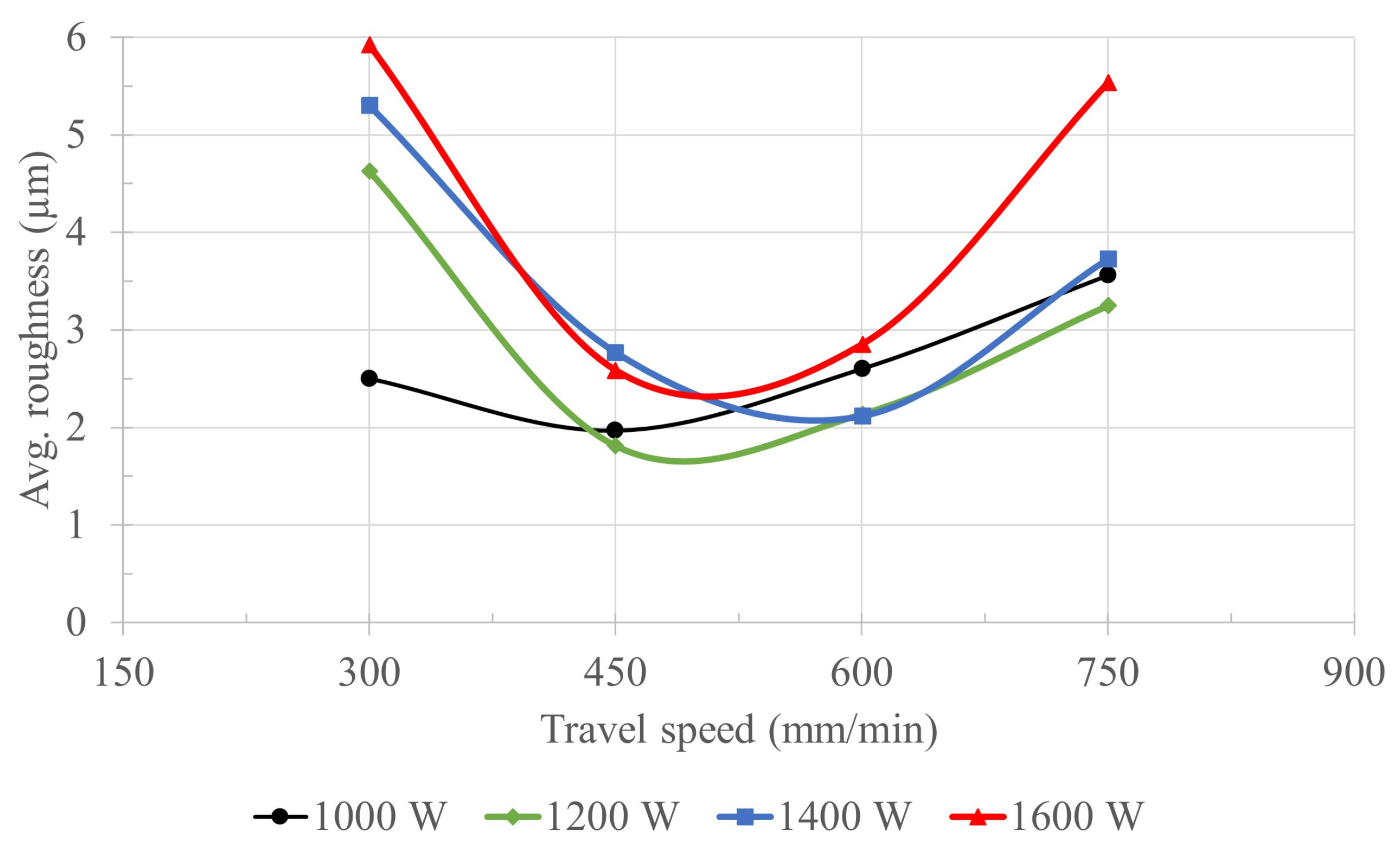
| Sample No. | 13 | 14 | 15 | 16 | 17 | 18 | 19 | 20 | 21 | 22 | 23 | 24 | 25 | 26 | 27 | 28 |
|---|---|---|---|---|---|---|---|---|---|---|---|---|---|---|---|---|
| Travel speed | 300 | 300 | 300 | 300 | 450 | 450 | 450 | 450 | 600 | 600 | 600 | 600 | 750 | 750 | 750 | 750 |
| (mm/min) | ||||||||||||||||
| CW laser | 1000 | 1200 | 1400 | 1600 | 1000 | 1200 | 1400 | 1600 | 1000 | 1200 | 1400 | 1600 | 1000 | 1200 | 1400 | 1600 |
| power (W) |
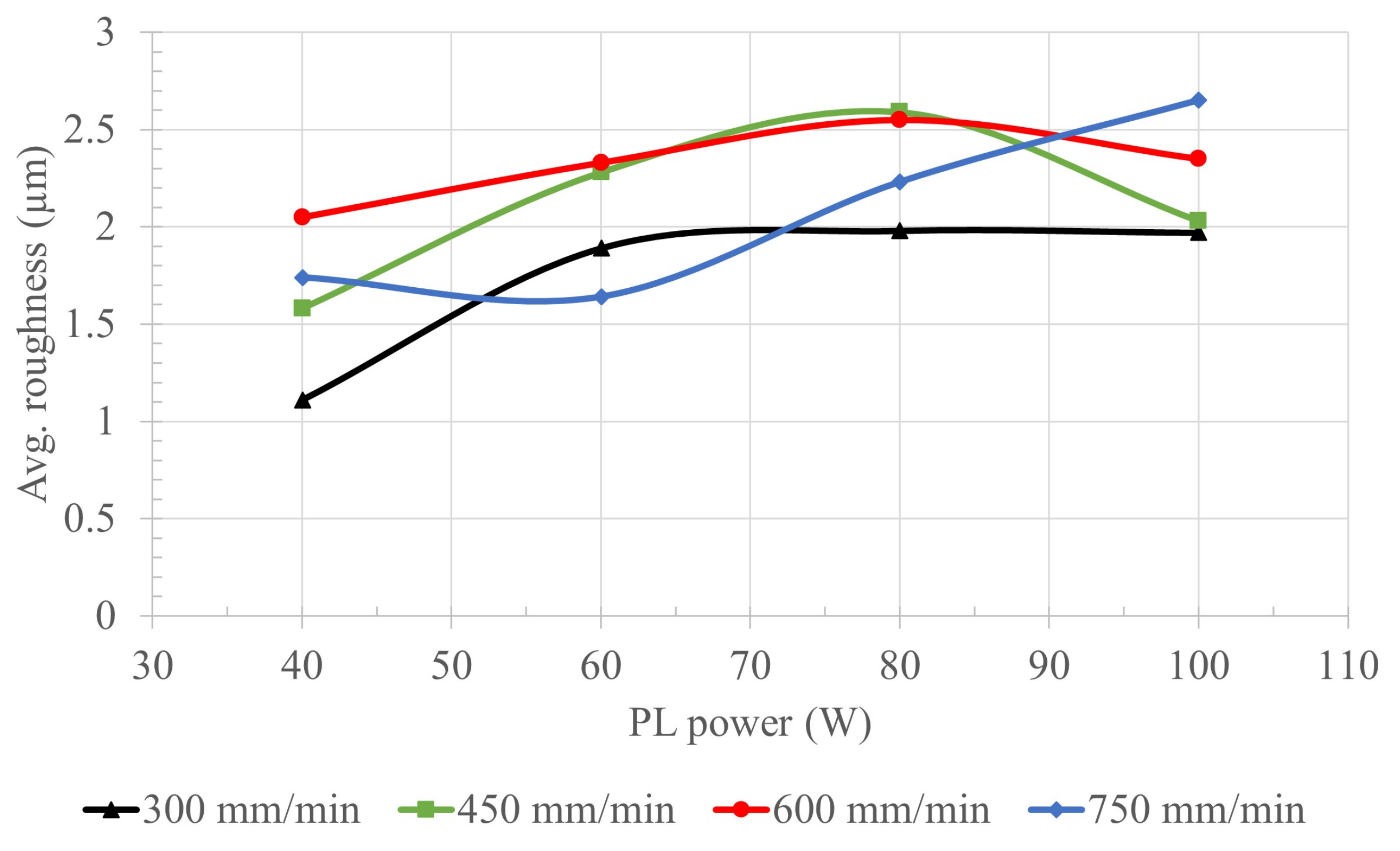
| Sample No. | 29 | 30 | 31 | 32 | 33 | 34 | 35 | 36 | 37 | 38 | 39 | 40 | 41 | 42 | 43 | 44 |
|---|---|---|---|---|---|---|---|---|---|---|---|---|---|---|---|---|
| Travel speed | 300 | 300 | 300 | 300 | 450 | 450 | 450 | 450 | 600 | 600 | 600 | 600 | 750 | 750 | 750 | 750 |
| (mm/min) | ||||||||||||||||
| Pulsed laser | 40 | 60 | 80 | 100 | 40 | 60 | 80 | 100 | 40 | 60 | 80 | 100 | 40 | 60 | 80 | 100 |
| power (W) |
Publisher’s Note: MDPI stays neutral with regard to jurisdictional claims in published maps and institutional affiliations. |
© 2021 by the authors. Licensee MDPI, Basel, Switzerland. This article is an open access article distributed under the terms and conditions of the Creative Commons Attribution (CC BY) license (https://creativecommons.org/licenses/by/4.0/).
Share and Cite
Parvez, M.M.; Patel, S.; Isanaka, S.P.; Liou, F. A Novel Laser-Aided Machining and Polishing Process for Additive Manufacturing Materials with Multiple Endmill Emulating Scan Patterns. Appl. Sci. 2021, 11, 9428. https://doi.org/10.3390/app11209428
Parvez MM, Patel S, Isanaka SP, Liou F. A Novel Laser-Aided Machining and Polishing Process for Additive Manufacturing Materials with Multiple Endmill Emulating Scan Patterns. Applied Sciences. 2021; 11(20):9428. https://doi.org/10.3390/app11209428
Chicago/Turabian StyleParvez, Mohammad Masud, Sahil Patel, Sriram Praneeth Isanaka, and Frank Liou. 2021. "A Novel Laser-Aided Machining and Polishing Process for Additive Manufacturing Materials with Multiple Endmill Emulating Scan Patterns" Applied Sciences 11, no. 20: 9428. https://doi.org/10.3390/app11209428
APA StyleParvez, M. M., Patel, S., Isanaka, S. P., & Liou, F. (2021). A Novel Laser-Aided Machining and Polishing Process for Additive Manufacturing Materials with Multiple Endmill Emulating Scan Patterns. Applied Sciences, 11(20), 9428. https://doi.org/10.3390/app11209428