Article

On the Improved Mechanical Properties of Ball-Milled GNPs Reinforced Short Chain Branched-Polyethylene Nanocomposite: Micromechanical Modeling and Fractography Study

by
Dimitra Kourtidou
1,
Konstantinos Tsongas
2,
Maria-Eirini Grigora
2,
Dimitrios Tzetzis
2,
Dimitrios N. Bikiaris
3 and
Konstantinos Chrissafis
1,*
1
Advanced Material and Devices Laboratory, School of Physics, Aristotle University of Thessaloniki, GR-541 24 Thessaloniki, Greece
2
Digital Manufacturing and Materials Characterization Laboratory, School of Science and Technology, International Hellenic University, 14 km Thessaloniki, GR-570 01 N. Moudania, Greece
3
Department of Chemistry, Laboratory of Polymer Chemistry and Technology, Aristotle University of Thessaloniki, GR-541 24 Thessaloniki, Greece
*
Author to whom correspondence should be addressed.
Appl. Sci. 2021, 11(20), 9420; https://doi.org/10.3390/app11209420
Submission received: 15 September 2021 / Revised: 29 September 2021 / Accepted: 6 October 2021 / Published: 11 October 2021
(This article belongs to the Special Issue Recent Advances in Technology for Polymer Composite Materials)

Abstract

:

Featured Application

Piping material for geothermal heat pump applications.

Abstract

Short-chain branched-Polyethylene (SCB-PE) is commonly utilized in hot and cold piping systems due to its high-temperature resistance. SCB-PE nanocomposites using graphene nanoplatelets (GNPs) as a reinforcing filler were synthesized in this work. The effect of the filler’s content and the ball-milling process on nanocomposites’ structure, tensile and shear properties was studied. Two series of nanocomposites have been prepared, one with and one without the ball-milling as a premixing step prior to the melt-mixing process. The ball-milling process induced a lower crystallinity degree of the SCB-PE nanocomposites than their solely melt-mixed counterpart. The tensile properties of the ball-milled samples presented a more profound enhancement with increasing filler content. The Ji and modified Halpin-Tsai micromechanical models were best fit to describe the experimental elastic modulus of the solely melt-mixed and the ball-milled nanocomposites, respectively. Fractography studies suggested that the detachment of the filler particles from the polymer matrix is avoided for lower GNPs contents of the ball-milled samples. Shear tests revealed that the shear strength increased and ductility decreased with increasing filler content in any case. The ball-milling process resulted in SCB-PE nanocomposites with superior mechanical properties compared to their solely melt-mixed counterparts.

Graphical Abstract

1. Introduction

Thermoplastic polyoefin materials are the most widely used polymers in piping systems. Their abrasion, corrosion and chemical resistance, lightweight, and good processability make them the ideal substitute for metal pipes [1]. More particularly, their utilization of domestic water piping systems drives the academic and industrial sectors to research and invest in the preparation of new types of polyoefins with improved physicochemical properties appropriate for the application of interest. Polyethylene of raised temperature resistance was developed to present enhanced long-term hydrostatic strength at higher temperatures without crosslinking, thus improving processability [2]. These properties result from its molecular structure, which contains short-chain branches (SCB-PE) introduced by copolymerizing ethylene with hexene or octene [3]. Nonetheless, the low thermal conductivity and mechanical properties of SCB-PE compared to the counterpart metal materials used in these systems limit its advantages and create the necessity for further improvement. More specifically, polymer materials used in geothermal piping systems, where ground heat exchange is a crucial parameter, should present adequate thermal conductivity combined with good temperature resistance and mechanical properties since these systems may experience changes in temperature (−4–46 °C) and pressure (up to 415 kPa) [4].
Adding a small amount of a reinforcing filler in a polymer matrix can lead to a multicomponent system with enhanced physicochemical properties, depending on the selected filler’s and matrix’s properties separately. For this reason, during the last decades, polymer composites and nanocomposites have been extensively studied to gain insights into the factors that control and affect the reinforcement effect and subsequently develop new ways of improving these systems’ fabrication. Carbon fillers such as graphene nanoplatelets (GNPs), expanded graphite (EG), carbon nanotubes (CNTs) etc., present outstanding mechanical performance, thermal and electrical conductivity and thus are widely used as a reinforcing material. Nonetheless, it is essential to mention that the extent of property reinforcement is inseparably linked to the filler’s dispersion and the filler-matrix interactions, as many studies suggest [5,6].
Many methods have been proposed in order to improve the filler’s dispersion in the polymer matrix [7,8,9,10]. However, ball-milling presents many advantages, i.e., it is environmentally friendly and industrially applicable [11,12,13]. Its operating principle is based on the mechanical forces generated by repeated events to the milling tools. These forces are then transferred to the inserted materials, the filler and polymer matrix, separating this way the filler’s aggregates [14]. Based on the applied conditions (milling time, temperature, rounds per minute etc.), various phenomena can occur, such as diffusion of the atoms, crack of the filler’s particles, and intimate mixing [14].
The main characteristic of a polymer nanocomposite affected by the filler’s dispersion is its mechanical properties. Improved distribution of the reinforcing particles leads to a more uniform distribution of the load transfer and an enhanced nanoconfinement effect [15,16,17]. Chien et al. have shown that ball-milling induced better dispersion and stronger interfacial interaction of modified multiwalled nanotubes (MWNTs) in a Polyamide-6, 6 (PA66) matrix, which resulted in improved mechanical properties at a lower filler loading [18]. Yang et al. have also prepared poly(butylene terephthalate) (PBT) nanocomposites containing modified nano-Sb2O3 particles dispersed by high-speed rotating and high-energy ball-milling. The results showed that better dispersion was achieved for the nanocomposites prepared by ball-milling resulting in better mechanical properties [19]. Polyetheretherketone (PEEK) filled with nano-SiO2 particles nanocomposites have also been fabricated by compounding via the ball-milling technique by Zhang et al. [20]. They reported substantial improvement in material stiffness [20].
Many efforts have been made to predict the nanocomposites’ tensile behavior using micromechanical models [21,22,23,24,25,26,27]. This has become a difficult task due to the nanocomposites’ peculiar behavior, depending on the matrix’s structure, filler’s dispersion, as already stated, the particles’ aspect ratio, the filler-filler and filler-matrix interactions etc. Various two-phase or three-phase micromechanical models will be tested in this work for the elastic modulus prediction of the prepared nanocomposites. Depending on the applied model, the filler’s and/or the matrix’s characteristics are taken into account.
The aim of the present work is to examine the effect of the ball-milling process as a premixing step prior to melt-mixing on the crystalline structure and tensile properties of polyethylene of raised temperature resistance/graphene nanoplatelets nanocomposites, which are referred to in this manuscript as SCB-PE nanocomposites. SCB-PE/GNPs nanocomposites were prepared using various filler contents of 0.5, 1, 2.5 and 5 wt.%. Two series of nanocomposites were synthesized, the first nanocomposites via direct melt-mixing and the second set with a premixing ball-milling step and subsequently melt-mixing. X-ray diffraction (XRD) analysis was employed to investigate the filler’s loading and the ball-milling effect on the prepared polymers’ crystalline structure. Tensile tests were applied on neat SCB-PE and its nanocomposites prepared with and without ball-milling in order to examine their tensile properties. At the same time, various micromechanical models were fitted on the experimental elastic modulus values of the nanocomposites. A fractography study using scanning electron microscopy was also employed to investigate the fracture mechanisms of neat SCB-PE as well as its nanocomposites in any case. Shear tests were conducted to evaluate the shear strength of SCB-PE nanocomposites. To the best of our knowledge, it is worth mentioning that the ball-milling effect on the tensile and shear properties and crystalline structure of polyethylene of raised temperature resistance (SCB-PE)/graphene nanocomposites has not yet been studied. Since this polymer is commonly used in piping systems, its mechanical properties optimization has become an appealing goal.

2. Materials and Methods

2.1. Materials

Metallocene medium-density polyethylene (polyethylene of raised temperature, SCB-PE Type I) under the trade name XP9000 was kindly supplied by Daelim (Seoul, Korea). It has a melt flow index of 0.6 g/10 min and a density of 935 kg/m3. Graphene nanoplatelets under the trade name xGNP M5 with an average thickness of 6 × 10⁻⁹ m and an average diameter of 5 × 10⁻⁶ m were supplied by XG Sciences Inc. (Lansing, MI, USA). The average surface area varied from 120 to 150 m2/g and the bulk density of the GNPs was 2200 kg/m3.

2.2. SCB-PE Nanocomposites Preparation

SCB-PE/GNPs nanocomposites were prepared by melt-compounding in a Haake–Buchler Reomixer model 600 (company: Thermo Fisher Scientific, Waltham, MA, USA) with rollerblades and a mixing head with a volumetric capacity of 6.9 × 10⁻⁵ m3. The GNPs’ content in the polymer matrix was 0.5, 1, 2.5 and 5 wt.%. The set temperature (180 °C) and torque speed (30 rpm) were continuously recorded during the mixing period. The components were mixed for 10 min. Following the melt mixing process, the prepared materials underwent a hot press shaping with an Otto Weber, Type PW 30 hydraulic press (company: P/O/WEBER, Remshalden, Germany) connected with an Omron E5AX Temperature Controller (company: Omron, Kyoto, Japan), at a 170 ± 5 °C temperature the films’ preparation of appropriate thicknesses in accordance with each measurement. The SCB-PE/GNPs nanocomposites are mentioned in this manuscript as SCB-PE/GNPs no BM.
For the preparation of the SCB-PE/GNPs nanocomposites, which were prepared using the high-energy ball milling (HEBM) method as a premixing step [13,28,29], SCB-PE mixtures containing 0.5, 1, 2.5 and 5 wt.% of GNPs were physically mixed for 10 min and then inserted into a Retsch centrifugal ball mill model S 100 (company: Retsch GmbH, Haan, Germany) for solid-state mixing. A cylindrical stainless steel jar of 50 mL with six steel balls of 10 mm diameter was used, and the prepared mixtures were milled for 1 h with a rotation speed of 500 rpm at room temperature. The ball-milled materials were then melt-mixed following the melt compounding procedure described above. These SCB-PE/GNPs nanocomposites are mentioned in this manuscript as SCB-PE/GNPs w BM.

2.3. Characterization Techniques

The prepared materials’ X-ray diffraction (XRD) patterns (10–30 mm thick) were obtained at Bragg–Brentano geometry, using a water-cooled Rigaku Ultima+ (company: Rigaku Corporation, Tokyo, Japan) diffractometer with CuKa radiation, a step size of 0.05° and a step time of 3 s, operating at 40 kV and 30 mA.
An Instron 3344 dynamometer (company: Instron, Norwood, MA, USA) with a crosshead speed of 50 mm/min was used to perform tensile tests on neat SCB-PE and its nanocomposites, according to ASTM D638-14. The specimens were dumb-bell-shaped (central portions 5 × 0.8 mm thick, 22 mm gauge length) and cut in a Wallace cutting press. The extracted results were averaged from at least five samples’ measurements to obtain the mean values of the elastic modulus, tensile strength at yield and breakpoint, and elongation at break.
Fractography studies were conducted via scanning electron microscopy (SEM) on all the prepared materials using the Jeol JSM-7610F Plus scanning microscope (company: JEOL Ltd., Tokyo, Japan), equipped with an AZTEC ENERGY ADVANCED X-act EDS Oxford analytical system (company: Oxford Instruments, Abingdon, UK), operating at 20 kV, probe current 45 nA, and counting time 60 s.
The influence of ball milling and graphene nanoplatelets on the shear strength of SCB-PE and SCB-PE/M5 specimens was evaluated according to ASTM D 732-17. A universal testing machine (company: Testometric, Rochdale, UK) has been used, equipped with a standard 15 mm flat design cylindrical puncture head. A die cavity with a mean diameter of 15 mm was achieved in each sample by shearing it against two pieces of metal. Prior to each shear test, the puncture head was lubricated. Shear tests were conducted with a crosshead speed of 5 mm/min at ambient temperature. Each test specimen was mounted on a metal fixture and punctured at the center with a punch tool. The shear strength, the energy to shear, and the SCB-PE nanocomposites’ ductility with and without ball milling were measured three times.

3. Results and Discussion

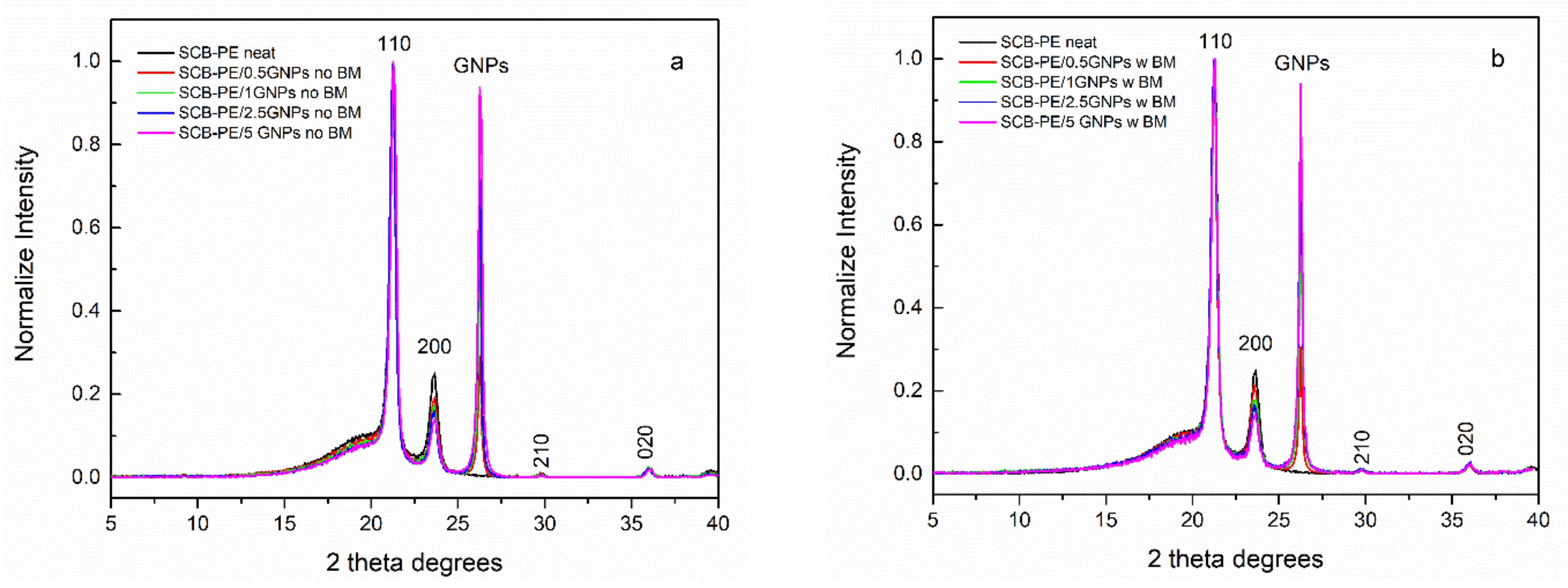
3.1. Structural Investigation

The ball-milling’s effect on the crystalline structure of SCB-PE/GNPs nanocomposites was studied using X-ray diffraction. The crystallinity degree of a polymer can affect its mechanical properties, i.e., the crystalline phase can lead to increased tensile strength [28,29]. Figure 1a,b present the XRD patterns of SCB-PE/GNPs no BM and SCB-PE/GNPs w BM nanocomposites, respectively, along with the diffractogram of neat SCB-PE. All the samples present distinct crystalline peaks corresponding to (110) and (200) planes of the orthorhombic (Pnam space group) phase of polyethylene, superimposed on an amorphous halo [24]. The SCB-PE/GNPs nanocomposites of any case present a sharp peak around 2θ ≈ 26.5°, which corresponds to the diffraction of the (002) crystal plane of GNPs [30]. It can be seen that with increasing filler content, the intensity of the GNPs’ diffraction peak increases, in any case of the nanocomposites. The crystallinity degree of all the prepared materials has been calculated using the following equation [31]:
X c % = A c r A c r + A a m · 100 ,
where Xc is the degree of crystallinity and Acr and Aam are the crystalline and amorphous peak areas, respectively.
The values of the crystallinity degree of all the prepared materials are presented in Table 1. As seen from the resulted Xc values, the incorporation of GNPs in the polymer matrix causes an increase in crystallinity. GNPs act as a nucleation site for the macromolecular polyethylene chains, leading to a higher crystalline volume fraction in any case of the nanocomposites with increasing filler content. However, a difference in the crystallinity degree between the ball-milled nanocomposites and their solely melt-mixed counterparts is observed. SCB-PE/GNPs w BM nanocomposites present lower Xc values, indicating that the ball-milling process induced the decrease of the lamellar density [32]. Despite the amorphization effect, the ball-milled nanocomposite samples present higher crystallinity values compared to neat SCB-PE. The lamellae thickness of the two main crystallographic directions (110) and (200) of the neat SCB-PE and its corresponding nanocomposites was calculated using Scherrer’s equation:
L h k l = K λ F W H M 2 θ cos θ ,
where FWHM is the full width at half maximum of the corresponding peak, K is a geometrical factor (for polyethylene is taken as 0.9 [33]), and λ is the wavelength of CuKa radiation (λCuKa = 1.5418 Å). The results are presented in Table 1. The lamellae thicknesses of the prepared materials do not present significant variations, meaning that the GNPs presence and the ball-milling process did not seem to affect the matrix’s crystalline size. This can also be verified by the almost constant and similar values of the ratio L110/L200 (Table 1).

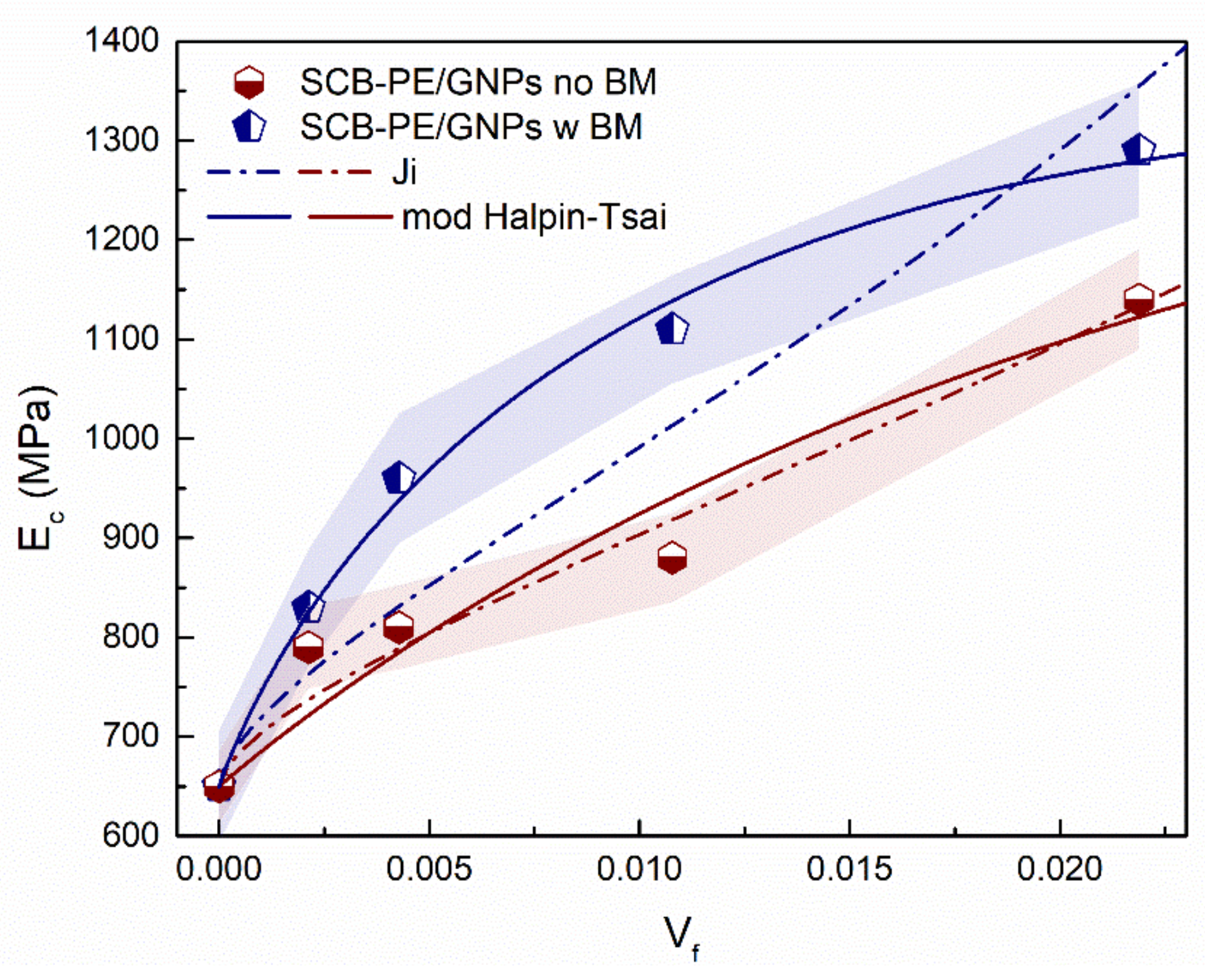
3.2. Tensile Properties

Tensile tests were conducted to estimate the tensile properties of all the prepared materials. Figure S1a,b in the supplementary data report, present the stress-strain curves of SCB-PE/ GNPs no BM and SCB-PE/ GNPs w BM respectively, along with neat SCB-PE. The estimated values of elastic modulus, tensile strength at yield and break, and elongation at break are reported in Table 2. In any case of the GNPs nanocomposites, the elastic modulus and the tensile strength at yield and break present higher values than neat SCB-PE. The reinforcement effect is a result of the effective stress transfer from the polymer to the GNPs. However, when the filler content exceeds 0.5 wt.%, the elongation at break decreases compared to neat SCB-PE. The presence of the GNPs particles restricts the macromolecular chains’ mobility during the stress application. This results in stress concentration around the filler’s particles and/or aggregates, where less energy is required to propagate a crack. Similar findings have been found by Tarani et al. for high-density polyethylene (HDPE)/GNPs nanocomposites [23].
Additionally, it is observed that the elastic modulus and tensile strength at yield of the SCB-PE/GNPs w BM nanocomposites are larger in value than those of the SCB-PE/GNPs no BM samples. Elastic modulus increased values of SCB-PE/GNPs w BM nanocomposites are in agreement with the results of nanoindentation tests presented in our previous work [34]. Tensile strength at break follows similar behavior except for the SCB-PE/0.5 GNPs no BM nanocomposite, which presents the highest stress at break. The deformation upon failure also takes the largest value among the rest of the prepared materials for this sample. Overall, the tensile properties of the ball-milled nanocomposites present a more significant enhancement compared to the ones that were solely melt-mixed. Better dispersion of the GNPs and improved interfacial adherence induced by the ball-milling process result in better tensile properties of the SCB-PE/GNPs w BM nanocomposites, despite being less crystalline. During the ball-milling step, GNP particles are coated by the polymer matrix. This polymer coating on the surface of GNPs reduces the van der Waals forces between the platelets, which are the main cause of the aggregates’ formation during the melt-mixing process, thus resulting in better dispersion of the filler in the SCB-PE matrix [34].
Similar results in regards to the elastic modulus improvement of thermoplastic/GNPs nanocomposites have been reported in the literature. More specifically, HDPE/GNPs nanocomposites prepared via melt-mixing containing 1wt. % filler content presented a 5% elastic modulus increase [23], while the corresponding augmentation for SCB-PE/1 GNPs w BM is 47.7%. Linear low-density polyethylene (LLDPE)/GNPs nanocomposites were also studied in terms of their physicomechanical properties. The tensile strength of the LLDPE/GNPs nanocomposite containing 1 wt. % GNPs increased by 5%; however, further increase in filler content led to reduced tensile strength values due to the agglomerated filler particles [35]. The corresponding increase of SCB-PE/1 GNPs w BM is 45%, suggesting that the reinforcing effect of the GNPs is significant even at lower filler loadings due to the effect of the ball-milling process.
The elastic modulus’ profound enhancement of SCB-PE/GNPs nanocomposites raises the interest to further study their elastic behavior, applying various models used to predict Young’s modulus of composite materials. These models take into account several factors through various assumptions (interfacial adhesion, filler dispersion, aspect ratio and shape of the particles, aggregates’ concentration etc.). Numerous equations were fitted to the experimental data for the micromechanical modeling to compare the different predictions for the prepared materials’ elastic modulus.
The first two models are the parallel (Voight) and series (Ruess) geometrical models and are described by Equations (3) and (4), respectively (rule of mixture method) [36]. In these models, the hypothesis is that the composite consists of two different piled-up phases in parallel and series geometry. The Voight model uses the assumption of the isostrain condition where the two phases experience the same strain while the stress is additive. The following equation describes the parallel model:
E c = E f V f + E m V m ,
where Ec, Ef and Em are the elastic moduli of the composite, the filler and the matrix, respectively and Vf and Vm are the volume fractions of the filler and the matrix.
In the Reuss model, the hypothesis is that the composite’s phases carry the same external load and the strain is additive. Equation (4) gives the predicted elastic modulus values according to this model:
1 E c = V f E f + V m E m ,
Takayanagi et al. introduced a combination of series-parallel and parallel-series two-phase models [21]. In this concept, the main assumption is that the polymer composite consists of a homogenous rigorous discontinuous phase and a homogeneous continuous matrix phase. The series-parallel (Takayanagi I) equation is the following:
1 E c = φ λ E f + 1 λ E m + 1 φ E m ,
while in the parallel-series (Takayanagi II) model, the modulus of a polymer composite is described by the following equation:
E c = λ φ Ε f + 1 φ E m 1 + 1 λ E m ,
where the product of the parameters φ and λ equals to the volume fraction of the filler phase. These parameters are related to the degree of series and parallel coupling of the system.
Ouali et al. introduced the percolation filler concept in Reuss’s model, considering the filler–filler interactions and describing a percolating network of filler’s inclusions in a continuous phase such as a polymer matrix [27]. The elastic modulus of the composite is described, in this case, based on the elastic moduli of each component. The equation that describes the elastic behavior of the composite is the following:
E f = 1 2 ψ + ψ V f E m E f + 1 V f ψ E f 2 1 V f E f + V f ψ E m ,
where
ψ = 0 ,   V f < V c   V f ( V f V c ) ( 1 V c ) ,   V f V c ,
and
V c = 0.7 r ,
where Vc is the percolation threshold of the filler in the polymer matrix, the parameter b takes a value 0.4 in the case of a 3-D structure and r is the aspect ratio of the filler particle. When ψ = 0 the Ouali model is identical to the series model.
Despite introducing the percolation concept, Ouali’s equation fails to describe the composites’ elastic modulus behavior when the filler particles form agglomerates in the matrix volume. In case there are filler aggregates in the polymer, considering that the composite consists of three phases, the elastic moduli and volume fractions of the matrix, the dispersed filler and the agglomerated filler are taken into account in order to rearrange the two-phase rule of mixture and Takayanagi series and parallel models. In order to calculate the volume fraction of each component, an f-switching function has been proposed [37]:
f V f = 0 ,   V f < V c 1 e A ( V f V c 1 ) 0.474 ,   V f V c ,
where A is an adjustable parameter. Using this function, the volume fractions of the dispersed and aggregated filler can be calculated according to the following equations:
V f a g g = f V f V f ,
V f d i s = 1 f V f V f ,
while the elastic moduli of the dispersed and aggregated filler are calculated using the equations:
E a g g = E f V f V c c ,
E d i s = 1 + h 1 V f 2 / 3 1 + h 1 ( V f 2 3 V f ) ,
where h = Ef/Em and c the percolation exponent.
Using the above, the modified parallel model is described by the following equation:
E c = V f a g g E a g g + V f d i s E d i s + ( 1 V f a g g V f d i s ) E m ,
The modified series model is written as:
E c = E a g g E d i s E m V f a g g E d i s E m + V f d i s E a g g E m + ( 1 V f a g g V f d i s ) E a g g E d i s ,
The modified Takayanagi I (series-parallel) and II (parallel-series) models are described by the following equations, respectively:
E c = 1 V f E m E a g g + V f ψ E d i s E a g g 1 V f ψ E m + ψ V f ψ E d i s + 1 ψ 2 E a g g ,
and
E c = ψ 1 V f E d i s E a g g + ψ V f ψ E m E a g g + 1 ψ 2 E m E d i s 1 V f E d i s + V f ψ E m ,
Halpin-Tsai’s model was also applied to the experimental elastic modulus data of the prepared SCB-PE/GNPs w BM nanocomposites. Halpin-Tsai’s approximation considers that the reinforcement effect derives from the presence of rigorous inclusions in the matrix without taking into account the filler–filler and filler–matrix interactions [25,38] when the nanocomposite consists of the polymer matrix and randomly oriented fibers. In this case, the nanocomposites’ modulus is described by the following equation:
E c = E m 1 + ξ η V f 1 η V f ,
where ξ = 2r and r the aspect ratio of the filler particle and η can be calculated using the following expression:
η = E f E m 1 E f E m + ξ ,
The Einstein model is also commonly used on the elastic moduli experimental data of nanocomposites [22]:
E c = E m 1 + B V f ,
where B is a constant parameter. B is related to the filler geometry and interfacial adhesion between the matrix and the filler particles. When this parameter’s value is up to 1, the adhesion between the filler and the matrix is considered poor. If the quality of adhesion is excellent, this value rises higher than 2.5.
Ji et al., using Takayanagi’s two-phase model, introduced a three-phase model that includes the matrix, the interfacial region and the filler, assuming that the filler particles (sphere-, cylinders or plate-shaped) are randomly distributed in the matrix [24]. The following equation describes the Ji model:
E c = E m 1 a + a β 1 a + a h 1 ln h + β 1 a + a β h + 1 2 + E f E m β 1 ,
where
a = 2 τ t c + 1 V f ,
and
β = V f ,
where h = Ei(0)/Em is the stiffness ratio of the interfacial modulus around the surface of the filler particle, Ei(0) (GPa), to the one of the matrix Em, tc (nm) the thickness of the filler’s particle and τ (nm) is the interphase’s thickness. The parameter τ equals 0 when the interfacial region’s influence is insignificant. In this case, the Ji model drops to the two-phase series-parallel Takayanagi model.
A modified Halpin-Tsai equation has been proposed to predict polymer/carbon nanotubes (CNTs) composites’ elastic modulus [39]. This modification considers the orientation of the CNTs, the agglomeration state of the filler, and the filler particle’s waviness. The composite’s elastic modulus follows Equation (19) with the difference of the η factor. According to the modified Halpin-Tsai model, η factor is given by the following equation:
η m = f R f A f W E f E m 1 f R f A f W E f E m + ξ ,
where fR the orientation factor that takes the value 1/6 for randomly oriented filler in three dimensions, and the length of the filler is much smaller than the specimen’s thickness [40]. fA is the agglomeration efficiency factor and is given by the Equation (26):
f A = exp a V f β ,
where parameters α and β are related to the agglomeration degree of the filler. The fW factor represents the waviness of the filler’s particles and is given by the following equation:
f W = 1 A W ,
where A and W are the amplitude and half-wavelength of a wavy platelet (in the case of GNPs), respectively.
The models described above were applied to the experimental data of SCB-PE/GNPs no BM and w BM nanocomposites. The results of the solely melt-mixed and the ball-milled samples are presented in the supplementary data report in Figure S2a,b, respectively. In both cases of the nanocomposites, the Voight and modified Voight models and the Halpin-Tsai and Ouali’s models overestimate the elastic modulus of the composites. On the other hand, both Takayanagi, Ruess and modified Ruess models result in much lower Ec values than the experimental ones for all the prepared nanocomposites. The elastic modulus values derived by the fitting of the Einstein model, while closer to the experimental data for both cases of the nanocomposites, present linear behavior resulting in poor fitting quality. The B parameter of the Einstein model for the SCB-PE/GNPs no BM nanocomposites equals 35.3, and the corresponding value for the ball-milled samples is 51.5, indicating that the interfacial adhesion between the filler particles and the matrix is better in the case of the SCB-PE/GNPs w BM nanocomposites.
The fitting of the Ji model on the experimental elastic modulus of the nanocomposites is presented in Figure 2. As seen, the Ji model results in Ec values close to the elastic modulus values of SCB-PE/GNPs no BM nanocomposite, while in the case of the ball-milled samples, this model presents large deviations from the experimental data. The derived values of the interfacial modulus Ei(0) and the interphase’s thickness τ for both cases of the nanocomposites are presented in Table 3. The Ei(0) of the SCB-PE/GNPs no BM is 74.54, while the corresponding value for the ball-milled nanocomposites is 98.67; These results indicate a more extensive reinforcement of the interfacial modulus of the SCB-PE/GNPs w BM samples, possibly induced by the ball-milling process, which causes stronger interfacial adherence between the filler particles and the polymer matrix. Likewise, the derived τ values for the SCB-PE/GNPs no BM and w BM nanocomposites are 29.45 and 43.9 nm, respectively, suggesting that the ball-milling step assists in the formation of a thicker interfacial layer around the platelet particle.
The predicted Ec by the modified Halpin-Tsai equation is also presented in Figure 2, along with the prepared materials’ experimental elastic modulus; the extracted results are shown in Table 3. As observed, the elastic modulus behavior of SCB-PE/GNPs w BM nanocomposites is better described by the modified Halpin-Tsai model compared to the Ji fitting on the experimental data. For the solely melt-mixed samples, the predicted Ec values, while close to the experimental data, present larger deviations than the ones of the Ji fitting. The fW parameter of the ball-milled samples presents a higher value compared to the solely melt-mixed samples, considering that the ball milling process causes a high curvature of the graphene nanoplatelets. The α parameter from Equation (26) holds a similar value in both cases of the prepared materials. On the other hand, the β parameter’s value of the SCB-PE/GNPs w BM is lower than that of the SCB-PE/GNPs no BM nanocomposites. Since this parameter is related to the degree of the filler’s agglomeration, it can be suggested that the ball-milled nanocomposites present better GNPs dispersion compared to the solely melt-mixed counterpart, thus resulting in higher values of elastic modulus.

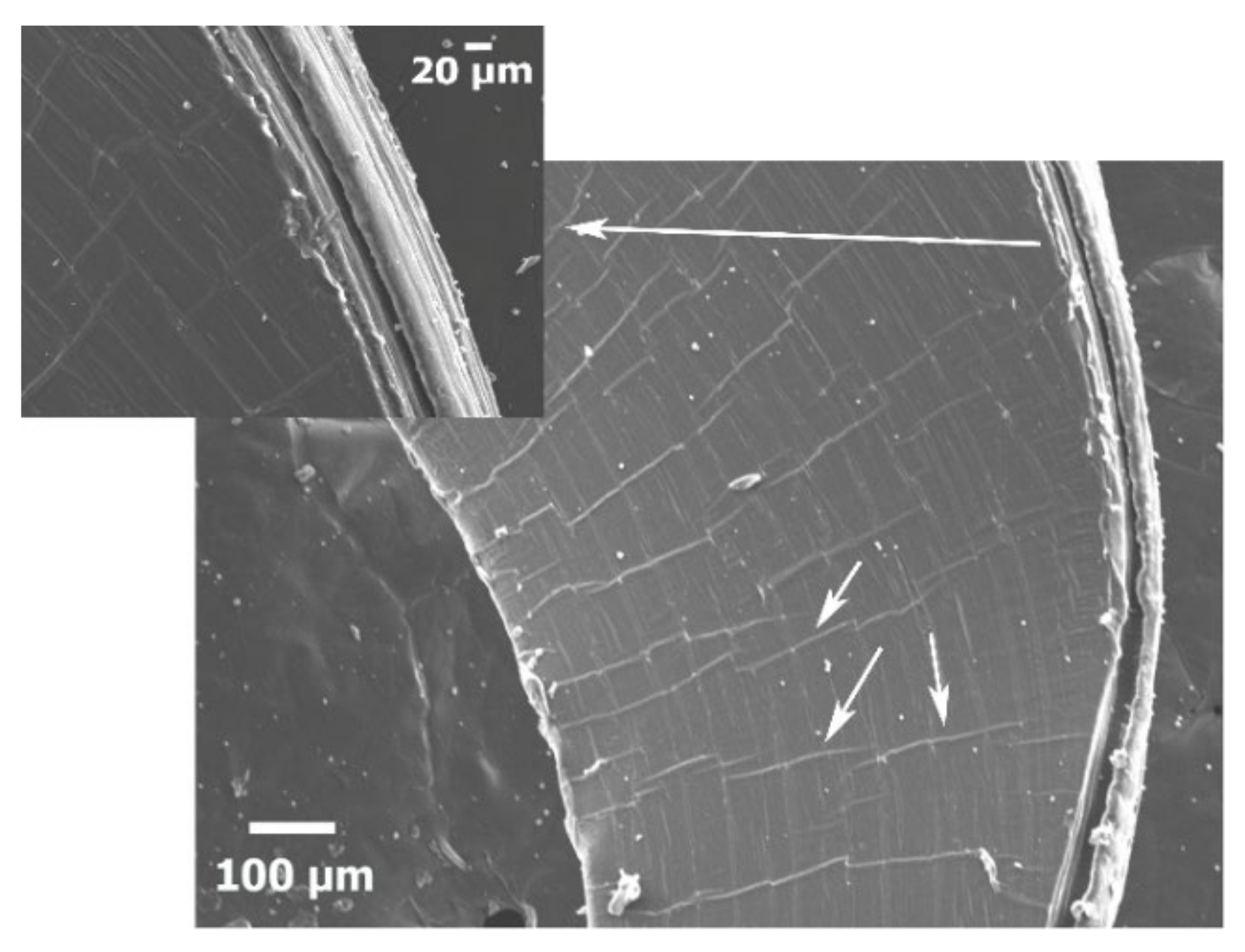
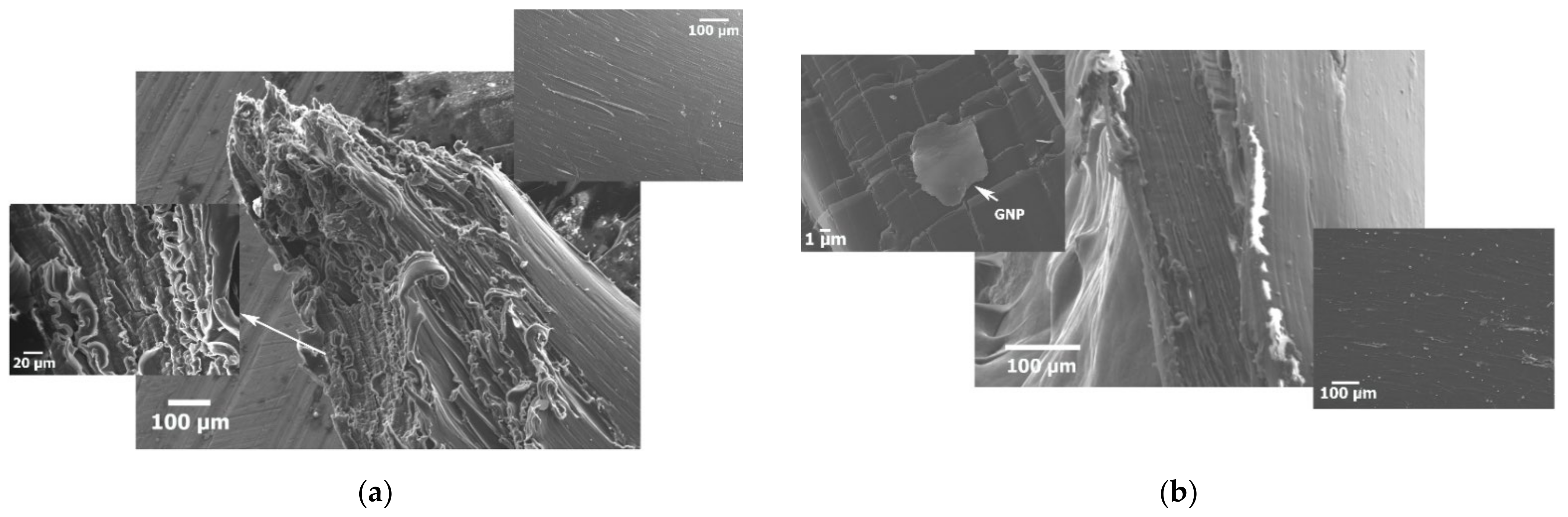
3.3. Scanning Electron Microscopy-Fractography Study

In order to evaluate the fracture mechanism of neat SCB-PE and all the prepared GNPs nanocomposites under tensile stress, the fracture surfaces of the samples after the tensile tests were observed using scanning electron microscopy. Figure 3 presents the fracture surface of neat SCB-PE. The sample’s plane view presents plastic tearing due to the share stresses applied parallel to the fracture plane and the chain stretching of the matrix. Some superficial voids are also observed, while no intense fibril formation occurs due to the homogenous polymer chain fracture during the macromolecular chains’ alignment and orientation caused by the uniaxial tensile stress [23].
The fracture surface of SCB-PE/0.5 GNPs no BM is presented in Figure 4a. The GNPs aggregates’ presence causes unevenly cut fibrils of the matrix as seen at the fracture surface’s cross-section. Some of these fibrils are curved due to the relaxation of the polymer after the failure. During the tensile stress application, the macromolecular chains’ movement is restricted by the entangled GNPs in the matrix, i.e., when the GNPs form inhomogeneously distributed aggregates, their presence block the further elongation of the amorphous and crystalline regions, causing stress concentration around these areas and abrupt cut of the polymer chains leading to the formation of the uneven fibrils. On the sample’s plane view, deep voids larger than 100 μm in length can be seen, caused by the fibrils’ stretching.
On the other hand, the failure surface of SCB-PE/0.5 GNPs w BM presented in Figure 4b is characterized by smoother areas, although voids larger than 100 μm but lesser in number compared to that of SCB-PE/0.5 GNPs no BM, can be observed on the plane view image. As mentioned, the elongation at break of SCB-PE/0.5 GNPs in both cases is even higher than that of neat SCB-PE. This could be attributed to the better GNPs dispersion and the stronger interfacial adhesion between the filler and the matrix. Homogeneously dispersed filler results in an evenly distributed stress transfer throughout the matrix. At the same time, good interfacial adhesion between the particle and the polymer induces a stronger bond, meaning that more stress must be applied in order for the particle to detach from the matrix and as a consequence, initiate a crack leading to the final fracture of the material [41]. During the application of the stress, a possible GNPs response is their alignment to the stress’s direction, allowing the further stretching of the lamellas and amorphous areas of the matrix, leading to a smoother fracture surface like the one seen in Figure 3.
Similar behavior of fracture with SCB-PE/0.5 GNPs no BM is presented on the SEM images of the failure surface of SCB-PE/1 GNPs no BM (Supplementary data Figure S3a). Unevenly cut fibrils and large voids are formed on the surface’s plane view due to the ununiformly distributed stress through the matrix caused by the GNPs aggregates and poor adhesion between the filler and the polymer. The fracture surface of SCB-PE/1 GNPs w BM is also presented in Figure S3b in the supplementary data report. The fibrils’ formation is apparent, presenting curved areas due to the polymer chains’ relaxation after the failure. However, the fibrils’ length seems longer, indicating a higher elongation at break and a homogeneous stress distribution in the polymer matrix. On the plane view of the fracture surface, it can also be seen that the GNPs act as a bonding agent preventing the voids from fully opening, thus acting as an obstacle to the crack formation during the stress application. The above leads to smoother surface areas around the fracture surface on the sample’s plane view, as presented in Figure S3b. This indicates a better dispersion of the GNPs in the polymer and a stronger interfacial bonding of the filler to the matrix induced by the ball milling process.
The fracture surface of SCB-PE/2.5 no BM is presented in Figure 5a. The abrupt cut is evident by the highly ununiformed length and thickness of the fibrils. Large voids appear on the plane view around the failure area due to the polymers’ stretching. Similar fracture behavior also presents the SCB-PE/2.5 GNPs w BM as seen in Figure 5b. The GNP content in these cases prevents the molecular chains’ movement during the stress application, while the denser dispersion of the filler can cause stress concentration in the matrix’s volume hindering the alignment of the GNPs along with the stress’s direction, as was in the case with lower filler content. One can identify identical characteristics to the fracture surface of SCB-PE/5 GNPs no and w BM, presented in Figure S4, in the supplementary data report. The difference occurs on the fibrils thickness, while in the case of the ball-milled sample, a possible detachment of the GNPs can be observed in the voids. In this case, the interfacial adhesion between the filler and the matrix was inadequate to prevent the voids’ formation during the stress application due to the stress concentration around the GNPs area and their dense dispersion in the polymer’s volume.

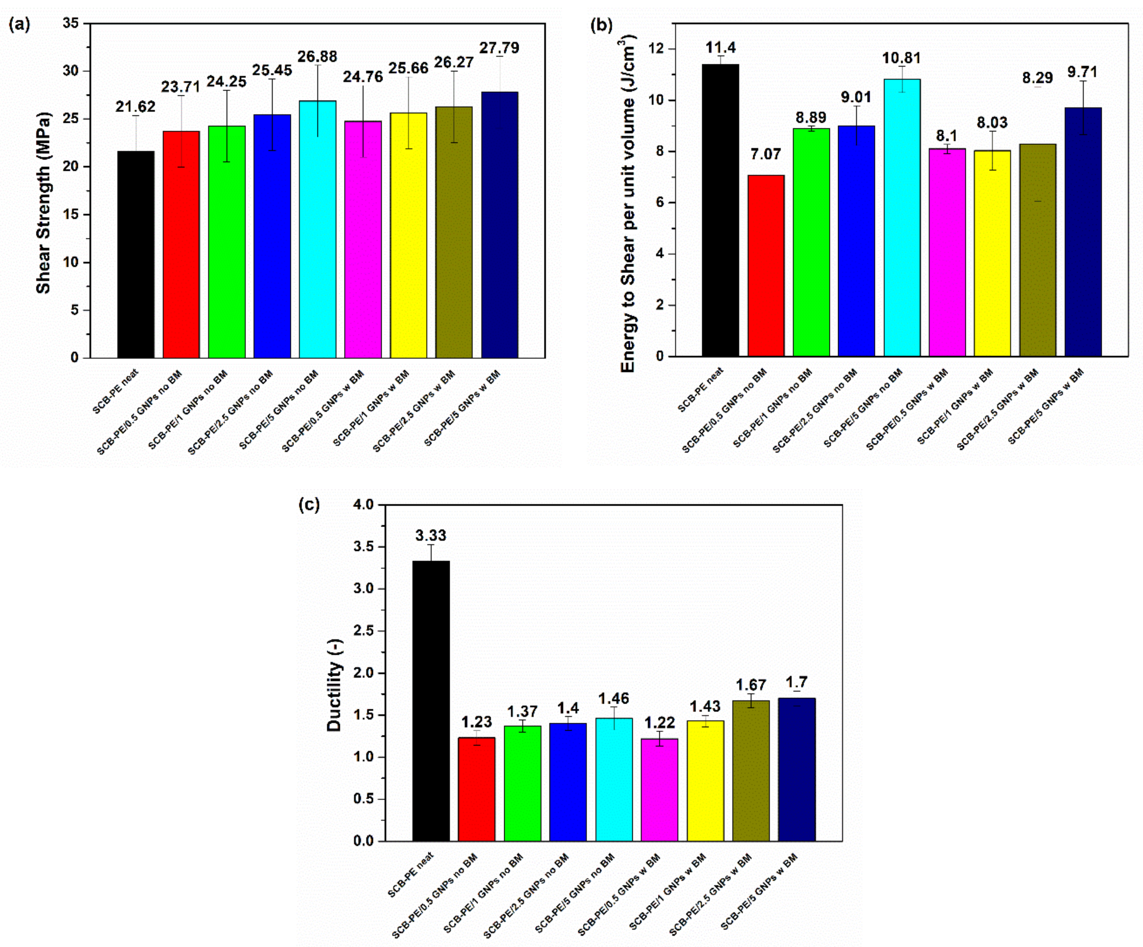
3.4. Shear Test Results

The mechanical properties of the specimens were measured using tensile testing of dog-bone specimens and shear tests by punch tool. The shear test is helpful for compliant materials that may stretch excessively and demonstrate misleading results when tested in the tensile mode. The most critical parameters are the peak load, the area under the load-displacement curve, and the punch probe’s displacement from initial contact up to the shear fracture of the film. From these data, shear strength and energy to shear were calculated. The nature of the test does not allow calculation of Young’s modulus or elongation to shear [42]. Shear strength is calculated based on Equation (28):
Shear strength (N/mm2) = F/Ac,
where F is the load required to shear the specimen and Ac is the area of the sheared edge, which shall be taken as the product of the specimen thickness by the circumference of the punch. The equation for energy to shear is similar to that of a tensile test, except for the calculation of the volume term. Hence, the energy to shear per unit volume is calculated by:
Energy to shear (J/cm3) = AS/VC,
where As is the area under the load-displacement curve of the shear tests and VC is the volume of the die cavity of the film holder. The displacement of shear punch until fracture of each specimen has been normalized by each specimen’s initial thickness and considered ductility.
The shear test data revealed that SCB-PE/5 GNPs w BM specimens have the highest shear strength, as shown in Figure 6a. These results agree with the ones derived from the tensile tests since the elastic modulus of SCB-PE/5 GNPs w BM was the highest among all samples examined. In addition, SCB-PE/5 GNPS w BM specimens had the lowest elongation at break. The neat SCB-PE specimens demonstrated the lowest shear strength. The results show a moderate increase of the shear strength for SCB-PE GNPS for both cases of the nanocomposites with increasing filler content. However, the ball-milled samples present higher shear strength augmentation compared to their solely mixed counterparts. The most probable cause of this behavior is that the shear stress required to fracture is higher for the SCB-PE/GNPs w BM nanocomposites due to the better dispersion and interfacial adherence between the GNPs and the polymer matrix [43]. That is, in the case of the ball-milled nanocomposites, the crack initiation is further delayed since there is a higher surface area for interfacial bonding; during the shear stress application, the internal “planes” of a fractured sample are strongly bonded by the filler particles causing resistance to sliding.
The values of energy to shear fracture are shown in Figure 6b. The neat SCB-PE specimens were the most resistant to shear and required the greatest amount of energy to shear fracture. A similar phenomenon occurred for the calculation of ductility presented in Figure 6c. Neat SCB-PE specimens were considered as the more ductile ones. This can be attributed to a combination of their high shear strength and relatively high elongation to fracture. It should be noted that for both tensile and shear testing, the addition of graphene nanoplatelets improved the strength of the specimens. The nanocomposites’ ductility was expected to decrease since, once the debonding of the particles from the matrix begins, the GNPs act as a crack initiation site [44,45,46].

4. Conclusions

The filler content and the ball milling effect on the tensile and shear properties of short-chain branched-polyethylene/graphene nanoplatelets nanocomposites were examined in this study. Two series of SCB-PE/GNPs nanocomposites with various filler loadings (0.5–5 wt.%) were synthesized; the one was solely melt-mixed, and the other was ball-milled prior to the melt-mixing process. X-ray diffraction analysis revealed that the ball-milling step induced a lower crystallinity degree on the ball-milled samples than the SCB-PE/GNPs no BM counterparts. The nanocomposites presented improved tensile properties in any case. The SCB-PE/GNPs w BM nanocomposites presented a more significant enhancement of the elastic modulus and tensile strength compared to the solely melt-mixed counterparts despite having a lower crystallinity degree, meaning that the controlling factors of the improved tensile properties are the GNPs’ dispersion and the interfacial adherence with the polymer matrix. The Ji micromechanical model successfully predicted the experimental elastic modulus of the SCB-PE/GNPs no BM nanocomposites, and the modified Halpin-Tsai model was the one that best described the elastic modulus behavior of the SCB-PE/GNPs w BM samples. Fractography studies suggest that, in the case of the ball-milled samples, the stress transfer between the filler and the matrix is more effective for lower filler content due to the better dispersion and interfacial adhesion of the GNPs and the polymer. Shear tests of the prepared materials showed that the nanocomposites’ shear strength increased with filler content while the ball-milled nanocomposites presented more significant augmentation compared to the SCB-PE/GNPs no BM counterparts in any case. On the other hand, the nanocomposite samples were characterized by lower ductility with increasing filler content than the neat SCB-PE, while the SCB-PE/GNPs no BM nanocomposites were the least ductile among all the prepared materials in general. To sum up, the use of the ball-milling as a premixing step induced better mechanical properties even at low GNPs content, reducing the cost of the overall fabrication process of the nanocomposites.

Supplementary Materials

The following are available online at https://www.mdpi.com/article/10.3390/app11209420/s1, Figure S1: Representative tensile stress vs strain curves of neat SCB-PE, (a) SCB-PE/GNPs no BM and (b) SCB-PE/GNPs w BM nanocomposites, Figure S2: Theoretical modeling of elastic modulus for the SCB-PE/GNPs no BM and SCB-PE/GNPs w BM nanocomposites’ experimental data as a function of filler volume fraction, using various micromechanical models, Figure S3: SEM images of the fracture surfaces of (a) SCB-PE/1 GNPs no BM and (b) SCB-PE/1 GNPs w BM, Figure S4: SEM images of the fracture surfaces of (a) SCB-PE/5 GNPs no BM and (b) SCB-PE/5 GNPs w BM.

Author Contributions

Conceptualization, D.T., D.N.B. and K.C.; methodology, D.K., K.T. and M.-E.G.; formal analysis, D.K., K.T. and M.-E.G.; investigation D.K., K.T. and M.-E.G. and D.T.; writing—original draft preparation, D.K., K.T. and M.-E.G.; writing—review and editing, D.K., K.T. and M.-E.G., D.T., D.N.B. and K.C.; supervision, D.T., D.N.B. and K.C. All authors have read and agreed to the published version of the manuscript.

Funding

The research work was supported by the Hellenic Foundation for Research and Innovation (HFRI) under the HFRI PhD Fellowship grant (Fellowship Number: 1123).

Institutional Review Board Statement

Not applicable.

Informed Consent Statement

Not applicable.

Data Availability Statement

The data presented in this study are available on request from the corresponding author.

Conflicts of Interest

The authors declare no conflict of interest.

References

  1. Gedde, U.W.; Viebke, J.; Leijström, H.; Ifwarson, M. Long-term properties of hot-water polyolefin pipes—A review. Polym. Eng. Sci. 1994, 34, 1773–1787. [Google Scholar] [CrossRef]
  2. Schramm, D. Polyethylene Used in Industrial Applications at Eleveated Temperatures; Holger Bruening Basell Polyolefine GmbH Industriepark Hoechst: Frankfurt, Germany; Detlef Schramm: Rotterdam, The Netherlands, 2017. [Google Scholar]
  3. Schramm, D.; Service, T.; Dow, D.; Gmbh, E.; Plastic, E.; Conference, P. Pe-Rt, a New Class of Polyethylene for Pipe. In Proceedings of the 25th International Conference on Offshore Mechanics and Arctic Engineering, Hamburg, Germany, 4–9 June 2006. [Google Scholar]
  4. Mendrinos, D.; Katsantonis, S.; Karytsas, C. Pipe materials for borehole heat exchangers. In Proceedings of the European Geothermal Congress, Strasbourg, France, 19–24 September 2016; pp. 19–24. [Google Scholar]
  5. Šupová, M.; Martynková, G.S.; Barabaszová, K. Effect of nanofillers dispersion in polymer matrices: A review. Sci. Adv. Mater. 2011, 3, 1–25. [Google Scholar] [CrossRef]
  6. Balasubramanian, K.B.N.; Ramesh, T. Role, effect, and influences of micro and nano-fillers on various properties of polymer matrix composites for microelectronics: A review. Polym. Adv. Technol. 2018, 29, 1568–1585. [Google Scholar] [CrossRef]
  7. Jankong, S.; Srikulkit, K. Preparation of Polypropylene/Hydrophobic Silica Nanocomposites. J. Met. Mater. Miner. 2008, 18, 143–146. [Google Scholar]
  8. Chae, D.W.; Kim, B.C. Characterization on polystyrene/zinc oxide nanocomposites prepared from solution mixing. Polym. Adv. Technol. 2005, 16, 846–850. [Google Scholar] [CrossRef]
  9. Pan, W.; Zou, H. Characterization of PAN/ATO nanocomposites prepared by solution blending. Bull. Mater. Sci. 2008, 31, 807–811. [Google Scholar] [CrossRef]
  10. Motaung, T.E.; Mochane, M.J.; Linganiso, Z.L.; Mashigo, A.P. In-situ Polymerization of Nylon-Cellulose Nano composite. Polym. Sci. 2017, 3, 1. [Google Scholar] [CrossRef]
  11. Ambrosio-Martín, J.; Gorrasi, G.; Lopez-Rubio, A.; Fabra, M.J.; Mas, L.C.; Lõpez-Manchado, M.A.; Lagaron, J.M. On the use of ball milling to develop poly(3-hydroxybutyrate-co-3-hydroxyvalerate)-graphene nanocomposites (II)—Mechanical, barrier, and electrical properties. J. Appl. Polym. Sci. 2015, 132, 42217. [Google Scholar] [CrossRef] [Green Version]
  12. Ambrosio-Martin, J.; Fabra, M.J.; López-Rubio, A.; Gorrasi, G.; Sorrentino, A.; Lagaron, J.M. Assessment of Ball Milling as a Compounding Technique to Develop Nanocomposites of Poly(3-Hydroxybutyrate-co-3-Hydroxyvalerate) and Bacterial Cellulose Nanowhiskers. J. Polym. Environ. 2016, 24, 241–254. [Google Scholar] [CrossRef] [Green Version]
  13. Delogu, F.; Gorrasi, G.; Sorrentino, A. Fabrication of polymer nanocomposites via ball milling: Present status and future perspectives. Prog. Mater. Sci. 2017, 86, 75–126. [Google Scholar] [CrossRef]
  14. Burmeister, C.F.; Kwade, A. Process engineering with planetary ball millss. Chem. Soc. Rev. 2013, 42, 7660–7667. [Google Scholar] [CrossRef] [PubMed]
  15. Taylor, P.; Shao, W.; Wang, Q.; Chen, Y.; Gu, Y. Preparation and Properties of Polypropylene/Vermiculite Nanocomposite Through Solid-State Shear Compounding (S3C) Method Using Pan-Mill Equipment. Mater. Manuf. Process. 2013, 6914, 37–41. [Google Scholar] [CrossRef]
  16. Xia, H.; Wang, Q.; Li, K.; Hu, G.H. Preparation of polypropylene/carbon nanotube composite powder with a solid-state mechanochemical pulverization process. J. Appl. Polym. Sci. 2004, 93, 378–386. [Google Scholar] [CrossRef]
  17. Ma, H.; Zeng, J.; Realff, M.L.; Kumar, S.; Schiraldi, D.A. Processing, structure, and properties of fibers from polyester/carbon nanofiber composites. Compos. Sci. Technol. 2003, 63, 1617–1628. [Google Scholar] [CrossRef]
  18. Chen, T.; Liu, H.; Wang, X.; Zhang, H.; Zhang, X. Properties and fabrication of PA66/surface-modified multi-walled nanotubes composite fibers by ball milling and melt-spinning. Polymers 2018, 10, 547. [Google Scholar] [CrossRef] [PubMed] [Green Version]
  19. Yang, W.; Xu, J.; Niu, L.; Kang, C.; Ma, B. Effects of high energy ball milling on mechanical and interfacial properties of PBT/nano-Sb2O3 composites. J. Adhes. Sci. Technol. 2018, 32, 291–301. [Google Scholar] [CrossRef]
  20. Zhang, G.; Schlarb, A.K.; Tria, S.; Elkedim, O. Tensile and tribological behaviors of PEEK/nano-SiO2 composites compounded using a ball milling technique. Compos. Sci. Technol. 2008, 68, 3073–3080. [Google Scholar] [CrossRef]
  21. Uemura, S.; Takayanagi, M. Application of the theory of elasticity and viscosity of two-phase systems to polymer blends. J. Appl. Polym. Sci. 1966, 10, 113–125. [Google Scholar] [CrossRef]
  22. Kourtidou, D.; Symeou, E.; Terzopoulou, Z.; Vasileiadis, I.; Kehagias, T.; Pavlidou, E.; Kyratsi, T.; Bikiaris, D.N.; Chrissafis, K. Graphite reinforced silane crosslinked high density polyethylene: The effect of filler loading on the thermal and mechanical properties. Polym. Compos. 2021, 42, 1181–1197. [Google Scholar] [CrossRef]
  23. Tarani, E.; Chrysafi, I.; Kállay-Menyhárd, A.; Pavlidou, E.; Kehagias, T.; Bikiaris, D.N.; Vourlias, G.; Chrissafis, K. Influence of graphene platelet aspect ratio on the mechanical properties of HDPE nanocomposites: Microscopic observation and micromechanical modeling. Polymers 2020, 12, 1719. [Google Scholar] [CrossRef]
  24. Ji, X.L.; Jing, J.K.; Jiang, W.; Jiang, B.Z. Tensile modulus of polymer nanocomposites. Polym. Eng. Sci. 2002, 42, 983–993. [Google Scholar] [CrossRef]
  25. Affdl, J.C.H.; Kardos, J.L. The Halpin-Tsai equations: A review. Polym. Eng. Sci. 1976, 16, 344–352. [Google Scholar] [CrossRef]
  26. Einstein, A. Über die von der molekularkinetischen Theorie der Wärme geforderte Bewegung von in ruhenden Flüssigkeiten suspendierten Teilchen. Ann. Phys. 1905, 322, 549–560. [Google Scholar] [CrossRef] [Green Version]
  27. Ouali, N.; Cavaille, J.Y.; Perez, J. Elastic, viscoelastic and plastic behavior of multiphase polymer blends. Plast. Rubber Compos. Process. Appl. 1991, 16, 55–60. [Google Scholar]
  28. Kourtidou, D.; Grigora, M.E.; Tsongas, K.; Terzopoulou, Z.; Tzetzis, D.; Bikiaris, D.N.; Chrissafis, K. Effect of ball milling on the mechanical properties and crystallization of graphene nanoplatelets reinforced short chain branched-polyethylene. J. Appl. Polym. Sci. 2021, 138, 50874. [Google Scholar] [CrossRef]
  29. Roumeli, E.; Paraskevopoulos, K.M.; Bikiaris, D.; Chrissafis, K. Effect of high energy ball milling on the structure and mechanical properties of cross-linked high density polyethylene. J. Mater. Sci. 2013, 48, 6753–6761. [Google Scholar] [CrossRef]
  30. Balani, K.; Verma, V.; Agarwal, A.; Narayan, R. Physical, Thermal, and Mechanical Properties of Polymers. In Biosurfaces; John Wiley & Sons, Ltd.: Hoboken, NJ, USA, 2015; pp. 329–344. [Google Scholar] [CrossRef]
  31. Amjadi, M.; Fatemi, A. Tensile behavior of high-density polyethylene including the effects of processing technique, thickness, temperature, and strain rate. Polymers 2020, 12, 1857. [Google Scholar] [CrossRef]
  32. Tarani, E.; Papageorgiou, D.G.; Valles, C.; Wurm, A.; Terzopoulou, Z.; Bikiaris, D.N.; Schick, C.; Chrissafis, K.; Vourlias, G. Insights into crystallization and melting of high density polyethylene/graphene nanocomposites studied by fast scanning calorimetry. Polym. Test. 2018, 67, 349–358. [Google Scholar] [CrossRef] [Green Version]
  33. Matthews, J.L.; Peiser, H.S.; Richards, R.B. The X-ray measurement of the amorphous content of polythene samples. Acta Crystallogr. 1949, 2, 85–90. [Google Scholar] [CrossRef]
  34. Zheng, Y.; Fu, Z.; Li, D.; Wu, M. Effects of ball milling processes on the microstructure and rheological properties of microcrystalline cellulose as a sustainable polymer additive. Materials 2018, 11, 1057. [Google Scholar] [CrossRef] [PubMed] [Green Version]
  35. Kang, J.; Li, J.; Chen, S.; Zhu, S.; Li, H.; Cao, Y.; Yang, F.; Xiang, M. Hydrogenated petroleum resin effect on the crystallization of isotactic polypropylene. J. Appl. Polym. Sci. 2013, 130, 25–38. [Google Scholar] [CrossRef]
  36. Khanam, P.N.; Almaadeed, M.A.; Ouederni, M.; Mayoral, B.; Hamilton, A.; Sun, D. Effect of two types of graphene nanoplatelets on the physico-mechanical properties of linear low-density polyethylene composites. Adv. Manuf. Polym. Compos. Sci. 2016, 2, 67–73. [Google Scholar] [CrossRef] [Green Version]
  37. Rao, N.; O’Brien, K.; Rao, N.; O’Brien, K. Mechanical Properties of Solid Polymers; John Wiley & Sons, Ltd.: Hoboken, NJ, USA, 1998; ISBN 9781444319507. [Google Scholar]
  38. Chatterjee, A.P. A model for the elastic moduli of three-dimensional fiber networks and nanocomposites. J. Appl. Phys. 2006, 100, 054302. [Google Scholar] [CrossRef]
  39. Halpin, J.C.; Kardos, J.L. Moduli of crystalline polymers employing composite theory. J. Appl. Phys. 1972, 43, 2235–2241. [Google Scholar] [CrossRef]
  40. Hassanzadeh-Aghdam, M.K.; Jamali, J. A new form of a Halpin-Tsai micromechanical model for characterizing the mechanical properties of carbon nanotube-reinforced polymer nanocomposites. Bull. Mater. Sci. 2019, 42, 117. [Google Scholar] [CrossRef] [Green Version]
  41. Cox, H.L. The elasticity and strength of paper and other fibrous materials. Br. J. Appl. Phys. 1952, 3, 72–79. [Google Scholar] [CrossRef]
  42. Hayward, M.R.; Johnston, J.H.; Dougherty, T.; De Silva, K. Interfacial adhesion: Improving the mechanical properties of silicon nitride fibre-epoxy polymer composites. Compos. Interfaces 2019, 26, 263–273. [Google Scholar] [CrossRef]
  43. Radebaugh, G.W.; Murtha, J.L.; Julian, T.N.; Bondi, J.N. Methods for evaluating the puncture and shear properties of pharmaceutical polymeric films. Int. J. Pharm. 1988, 45, 39–46. [Google Scholar] [CrossRef]
  44. Namdev, A.; Telang, A.; Purohit, R. Effect of Graphene Nano Platelets on Mechanical and Physical Properties of Carbon Fibre/Epoxy Hybrid Composites. Adv. Mater. Process. Technol. 2021, 2021, 1–14. [Google Scholar] [CrossRef]
  45. Bellemare, S.C.; Bureau, M.N.; Denault, J.; Dickson, J.I. Fatigue crack initiation and propagation in polyamide-6 and in polyamide-6 nanocomposites. Polym. Compos. 2004, 25, 433–441. [Google Scholar] [CrossRef] [Green Version]
  46. El Aboudi, I.; Mdarhri, A.; Brosseau, C.; Montagne, A.; Elhaouzi, F.; Bouyahia, Z.; Iost, A. Investigating carbon-black-filled polymer composites’ brittleness. Polym. Bull. 2020, 77, 4959–4969. [Google Scholar] [CrossRef]
Figure 1. XRD patterns of (a) neat SCB-PE and SCB-PE/GNPs no BM, (b) neat SCB-PE and SCB-PE/GNPs no BM.
Applsci 11 09420 g001
Figure 2. Theoretical modeling of elastic modulus for the SCB-PE/GNPs no BM and SCB-PE/GNPs w BM nanocomposites’ experimental data as a function of filler volume fraction, using the Ji and modified Halpin-Tsai models.
Applsci 11 09420 g002
Figure 3. SEM images of the fracture surface of SCB-PE after tensile test.
Applsci 11 09420 g003
Figure 4. SEM images of the fracture surfaces of (a) SCB-PE/0.5 GNPs no BM and (b) SCB-PE/0.5 GNPs w BM.
Applsci 11 09420 g004
Figure 5. SEM images of the fracture surfaces of (a) SCB-PE/2.5 GNPs no BM and (b) SCB-PE/2.5 GNPs w BM.
Applsci 11 09420 g005
Figure 6. (a) Bar chart comparing shear strength measured from mechanical tests, (b) bar chart comparing energy to shear measured for all SCB-PE specimens, and (c) ductility of the specimens.
Applsci 11 09420 g006
Table 1. Crystallinity degree values, lamellae thickness of (110) and (200) polyethylene’s crystalline planes and L110/L200 ratio of neat SCB-PE, SCB-PE/GNPs no BM and SCB-PE/GNPs w BM nanocomposites.
SampleL110 (Å)L200 (Å)L110/L200Xc%
neat SCB-PE97.232.8353.5
SCB-PE/0.5 GNPs no BM100.333.7356.3
SCB-PE/1 GNPs no BM102.933.13.162.4
SCB-PE/2.5 GNPs no BM101.434.62.966.4
SCB-PE/5 GNPs no BM99.833.3369.4
SCB-PE/0.5 GNPs w BM103.534353.6
SCB-PE/1 GNPs w BM101.834.4356.2
SCB-PE/2.5 GNPs w BM100.833.8357.9
SCB-PE/5 GNPs w BM103.834.2360.7
Table 2. Elastic modulus, tensile strength at yield and break, and elongation at break values of neat SCB-PE, SCB-PE/GNPs no BM and SCB-PE/GNPs w BM nanocomposites.
SampleElastic Modulus (MPa)Tensile Strength at Yield (MPa)Tensile Strength at Break (MPa)Elongation at Break (%)
neat SCB-PE650 ± 3715 ± 1.321.3 ± 5.2623 ± 126
SCB-PE/0.5 GNPs no BM790 ± 4219.6 ± 0.629.6 ± 6.3710 ± 152
SCB-PE/1 GNPs no BM810 ± 4219.5 ± 121.9 ± 3.1590 ± 91
SCB-PE/2.5 GNPs no BM880 ± 4520.1 ± 122.3 ± 2.2589 ± 88
SCB-PE/5 GNPs no BM1140 ± 5122.6 ± 0.821.8 ± 3.2421 ± 123
SCB-PE/0.5 GNPs w BM830 ± 5820.8 ± 0.626.4 ± 3.7646 ± 110
SCB-PE/1 GNPs w BM960 ± 6521.8 ± 127.2 ± 3.6583 ± 87
SCB-PE/2.5 GNPs w BM1110 ± 5523.1 ± 0.428.7 ± 2.5424 ± 103
SCB-PE/5 GNPs w BM1290 ± 6825.3 ± 1.228.3 ± 1.3342 ± 121
Table 3. Elastic modulus, tensile strength at yield and break, and elongation at break values of neat SCB-PE, SCB-PE/GNPs no BM and SCB-PE/GNPs w BM nanocomposites.
ModelA/ASample
SCB-PE/GNPs no BMSCB-PE/GNPs w BM
JiEi(0) (GPa)74.5498.67
τ (nm)29.4543.9
R20.9640.859
Modified Halpin-TsaifW0.230.94
α9.749.88
β0.760.47
R20.9280.992
Publisher’s Note: MDPI stays neutral with regard to jurisdictional claims in published maps and institutional affiliations.

