Abstract
For high-fidelity quantum operations in ion traps, it is important to maintain the secular frequency of the trapped ions at a constant value. The radial secular frequency is proportional to the amplitude of the radio frequency (RF) signal applied to ion traps. Owing to the changes in the ambient temperature of a helical resonator and the minute vibration of the optical table, the amplitude can vary. Recently, a method for reducing the fluctuation in the RF signal amplitude, using a commercial universal proportional-plus-integral (PI) controller, has been introduced, which, in turn, reduces the secular frequency drift of the trapped ions. The method improves the capability to maintain the secular frequency at a constant value. However, the structure of the controller is fixed; thus, the control method cannot be changed to suit different experimental conditions, and the different feedback configuration cannot be implemented to increase the resolution. In this paper, we develop a field-programmable gate array (FPGA)-based feedback controller that allows the implementation of various automatic control methods and feedback configurations. In our experiments, the fluctuation in the amplitude of the RF signal was 1.806% using a commercial universal PI controller. The fluctuation was reduced to 0.099% using the developed FPGA-based PI controller, and to 0.102% using the developed FPGA-based lag compensator. By employing the developed FPGA control method, many other automating control methods can be applied to achieve a stable and high-performance control of the secular frequency.
1. Introduction
The development of high-fidelity quantum gates with trapped ions is very important for quantum computing [1,2,3,4,5]. In the realization of ion trap-based quantum computing systems, the motional mode of the trapped ions is applied for quantum computation [6,7,8,9]. The frequency of the motional mode must be fixed as the quantum gate fidelity decreases when the frequency drifts. Since the frequency of the motional mode and secular frequency of the trapped ion are directly related, the drift of the secular frequency affects the reliability of the internal state manipulation. The noisy secular frequency excites the motional state and produces heating [10]. In addition, the noisy frequency changes the parameters such as the trap depth and position in the ion shuttling experiment [11,12]. Therefore, the secular frequency must be accurately controlled [13,14]. If the mass of the trapped ion, and the distance between the trapped ion and the electrodes of the ion trap do not change, the secular frequency ω can be expressed as follows [13,15,16,17,18]:
where and denote the amplitude and frequency of the radio frequency (RF) signal applied to the ion trap, respectively. Since the frequency of the RF signal from a signal generator does not drift, the secular frequency of the trapped ion changes only by the amplitude of the RF signal. The amplitude is increased by an RF amplifier and a helical resonator [18], which is vulnerable to the changes in the ambient temperature of the helical resonator and vibration of the optical table. These factors cause a drift in the resonant frequency and eventually change the amplitude of the RF signal. Therefore, the amplitude of the RF signal increased by the helical resonator needs to be maintained at a constant value. The change in the ambient temperature and the vibration of the optical table are less than a few kHz. Resistors, capacitors, and other electrical components may also be slightly affected by these factors. However, those effects are ignored because the bandwidth of the field-programmable gate array (FPGA)-based feedback controller developed in this paper is 133 kHz.
A method for reducing the fluctuation in the amplitude of the RF signal applied to the ion trap, using a commercial universal proportional-plus-integral (PI) controller (LB1005), has been developed [13]. With this method, the control method cannot be changed to suit different experimental conditions, including derivative control or lead–lag compensation. It is also well known that a PI controller can have a long-term drift error. In addition, the feedback configuration cannot be changed to increase the resolution of the controller. The developed method is also unable to increase the bandwidth of the PI controller to more than 1 MHz (LB1005 limited to 1 MHz). We implement the use of a feedback controller that is similar to that developed in the previous work and define it as the baseline method. Subsequently, we compare this method with the field-programmable gate array (FPGA)-based feedback control method under the same conditions. When using the baseline method, the fluctuation in the amplitude of the RF signal is 1.806%. The amplitude is measured by an analog-to-digital converter (ADC). In this paper, we develop a method for reducing the fluctuation in the amplitude of the RF signal using FPGA-based feedback control [19,20]. With this method, the control method can be freely selected, and various feedback configuration for increasing the resolution can be implemented. Furthermore, we design and utilize a PI controller and a lag compensator using Verilog. With the FPGA-based PI controller and lag compensator, the fluctuations in the amplitude of the RF signal are 0.099% and 0.102%, respectively. These values are 94.510% and 94.359% lower, respectively, than that obtained with the baseline method.
2. Experimental Environment
We did not connect the helical resonator to a vacuum chamber equipped with an ion trap. A helical resonator mounted on a vacuum chamber is considerably less vulnerable to the changes in the ambient temperature of the helical resonator and the minute vibration of the optical table compared with the unmounted one. Figure 1 presents the system for the amplification of the RF signal using the helical resonator. We used a 10 pF capacitor instead of a fabricated ion trap. We measured the resonant frequency and resonance width using the helical resonator with the 10 pF capacitor and a voltage divider to find the quality factor of the resonator with the devices [21,22,23]. The resonant frequency of the helical resonator was 23.342 MHz, and the resonance width was 149 kHz. Therefore, the helical resonator has a quality factor of 156.7. The helical resonator is fastened by an anodized aluminum breadboard and holder, and stainless-steel posts.
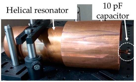
Figure 1.
An experimental structure amplifying the RF signal applied to ion traps using a helical resonator.
Direct current (DC) voltage, an output of a feedback controller, and an RF signal generated from a signal generator (Tektronix AFG3021C, Beaverton, OR, USA) were applied to a frequency mixer (Mini-Circuits ZX05-1L-S+, New York, NY, USA). The amplitude of the mixed signal was increased 63 times by an RF amplifier (Mini-Circuits ZX60-100VH+, New York, NY, USA). In addition, the peak-to-peak voltage was increased to 312 V through the helical resonator. To measure the amplitude of the RF voltage, we mounted a capacitive voltage divider at the output of the helical resonator. The amplitude of the RF signal was reduced to 1/1000 by the voltage divider. Then, the RF signal was converted by the rectifier to the DC voltage and applied to the feedback controller.
3. FPGA-Based Feedback Control
3.1. Previous Results
It has been shown that the drift of the secular frequency of trapped ions can be reduced using a commercial universal PI controller (LB1005) [13]. The amplitude of the RF signal applied to the ion traps is obtained by mounting a capacitive voltage divider inside a helical resonator. The obtained RF signal was converted to a DC signal by a rectifier. The difference between the DC signal and set-point voltage was used as the error signal of the commercial universal PI controller. Then, the DC voltage, the output of the controller, and the RF signal from the signal generator were applied to the frequency mixer. The amplitude of the mixed signal was increased by the RF amplifier and helical resonator. Using this method, the drift of the secular frequency of the trapped ion was reduced from 0.25% to 0.05% [13].
3.2. Baseline
As the baseline for comparison, we set up a system similar to that developed in a previous study [13], using a commercial universal PI controller (LB1005). Figure 2 presents the block diagram of the system. The output of a digital-to-analog converter (DAC) (Texas Instruments DAC8734, Dallas, TX, USA) was utilized as the set-point voltage. In addition, the helical resonator in the baseline method was not connected to a vacuum chamber. These conditions are different from those of the previous work. The heat capacity of a general vacuum chamber is significantly greater than that of the helical resonator. A substance with a large heat capacity is less sensitive to changes in the ambient temperature compared to a substance with a small heat capacity. Moreover, the substance with large heat capacity is also less sensitive to physical impacts than that with a small heat capacity. Therefore, the helical resonator mounted on a vacuum chamber is less sensitive to the changes in the ambient temperature of the helical resonator and the minute vibration in the optical table than the unmounted one. In this system, the fluctuation in the amplitude of the RF signal was 1.806%, which is larger than that in [13]. We will demonstrate in the following sections how a more advanced control architecture can reduce the amplitude fluctuation.
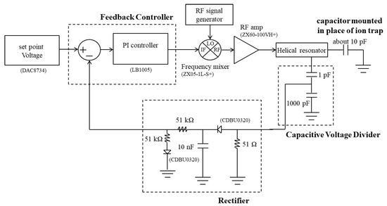
Figure 2.
A block diagram of the closed-loop feedback control system for reducing the fluctuation of the amplitude of the RF signal, using a commercial universal proportional-plus-integral (PI) controller.
3.3. FPGA-Based Feedback Controller
To achieve better performance, we developed a control hardware system using an ADC, a DAC, and an FPGA. Figure 3 presents the block diagram of the closed-loop feedback control system for reducing the fluctuation in the amplitude of the RF signal applied to ion traps using this method. The RF signal is converted by the ADC (Texas Instruments ADS8698EVM-PDK, Dallas, TX, USA) to digital data. Then, the closed-loop control input is calculated by the FPGA (Digilent ARTY S7, Pullman, WA, USA). The calculated data are then converted by the DAC (Texas Instruments DAC8734, Dallas, TX, USA) to an analog signal. The FPGA-based system allows changing the control method as well as the feedback configuration. In this paper, we added a voltage adder circuit to the output of the DAC and a subtractor circuit to the input of the ADC, which was very effective in increasing the resolution and hence in regulating the secular frequency. This would not be possible in the commercial servo method.
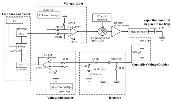
Figure 3.
A block diagram of the closed-loop feedback control system for reducing the fluctuation of the amplitude of the RF signal, using the field-programmable gate array (FPGA)-based feedback controller.
3.3.1. Finite-State Machine
Figure 4 presents the conceptual diagram of the finite-state machine (FSM) for controlling an ADC, a DAC, and a PI controller (or a lag compensator). The FSM initially starts with WAIT. When we enter the command UPDATE start into an FPGA using the serial communications of a personal computer, the state of the FSM switches from WAIT to UPDATE. Then, we can enter the parameter values, such as the proportional gain and integral gain of a PI controller, the pole and zero of a lag compensator, the sampling period, and the set-point voltage into the FPGA. When we enter the command LOAD start, the FPGA enters the information in the range of the input and the channel to accept the signals into the ADC. When the operation is complete, UPDATE and LOAD are automatically switched to WAIT. When the commands are entered, such as ADC on, Controller on, and DAC on, the state of the FSM switches to the corresponding state. The commands such as ADC off, Controller off, and DAC off return the state to WAIT. In ADC, an analog data entered into the ADC is converted into digital data and stored in the FPGA. In Controller, the output of the feedback controller is calculated to reduce the difference between the digital data and set-point voltage. In DAC, the calculated data is converted to analog data using the DAC. The output of the DAC changes to a new value every 7.5 μs, and the cycle is repeated. The DAC continues to supply the voltage of the previous cycle until it receives the new value.
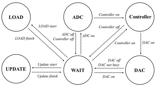
Figure 4.
A diagram of the finite-state machine of the FPGA-based feedback controller.
3.3.2. Aluminum Enclosure
The magnetic field around the feedback controller can affect the cables connected to the DAC, ADC, FPGA, and printed circuit board (PCB). The devices are mounted inside the aluminum enclosure to shield them from outside electromagnetic fields. We use two linear power suppliers to supply power with little noise to the DAC and PCB, including two regulators, a voltage adder, and a voltage subtractor. The resolution of the FPGA-based feedback controller is increased by the voltage subtractor and voltage adder. In the circuits, regulators (STMicroelectronics LM317, Geneva, Switzerland) are used. The op amps (Texas Instruments LM324, Dallas, TX, USA) are used in the circuits, such as the voltage follower, voltage adder, and voltage subtractor. The aluminum enclosure and the layout of the PCB are shown in Figures S1 and S2, respectively.
3.3.3. Design of the Controllers
In Figure 5a, the step response of the unity feedback circuit of a plant is presented. We use a PI controller and lag compensator to implement an FPGA-based closed-loop control. The forms of unity feedback using a PI controller and lag compensator are presented in Figure 5b,c, respectively. To model the helical resonator, which is the plant of the feedback control, we measure the corresponding output signal, thus changing the frequency of the input of the helical resonator. The transfer function G(s) of the model is as follows:
where and denote the output and input of the plant, respectively. The transfer function has two poles, s = −1.122 × 10⁵ ± j 2.318 × 10⁷, and one zero s = −2.415 × 10⁷. The overshoot and settling time of the plant was calculated in MATLAB as 135.38% and 34.94 μs, respectively. By applying the step input to the plant, the steady-state error of the unity feedback can be obtained as follows:
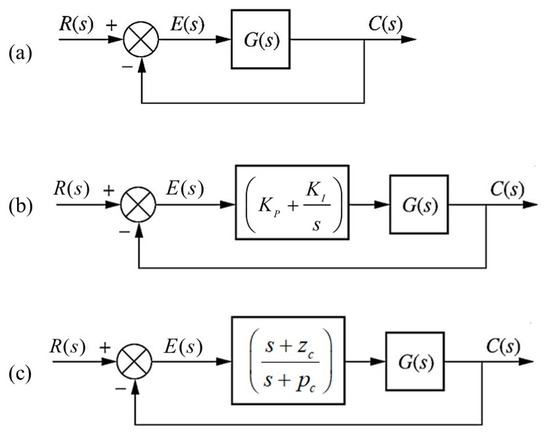
Figure 5.
Conceptual diagrams of the unity feedback. (a) Unity feedback without the use of any controller. (b) Unity feedback using a PI controller. (c) Unity feedback using a lag compensator.
We designed a PI controller and lag compensator that can reduce the overshoot and maintain the settling time at less than 1 s, which does not have much of an effect on the experiments with the ion traps, while at the same time having the lowest steady-state error.
As previously defined, a PI controller is a proportional-plus-integral controller that feeds an error (proportional) plus the integral of the error (integral) to a plant [24]. It uses a pure integrator that places the pole of the controller at the origin to reduce the error to zero. Moreover, it can be expressed as follows:
where , , and denote the proportional gain of the controller, integral gain of the controller, and error signal, which is the difference between the set-point voltage and input of an ADC, respectively. Discretization is required to enable the use of the PI controller in Verilog. Using the backward Euler method, we replace s with ; the terms of (4) becomes:
where T denotes the period of the cycle. Equation (4) can be expressed as follows:
When the PI controller is used, there are no gains to reduce the steady-state error and overshoot together. Further, we found the two gains that reduced the errors the most through trial and error. When the proportional gain and integral gain of the PI controller are 2.21 × 10⁻⁴ and 5.81, respectively, the overshoot and settling time are 135.41% and 34.94 μs, respectively, with the least steady-state error.
A lag compensator does not use a pure integrator; it places the pole near the origin [24] and takes the following form:
where and denote the pole and zero of the lag compensator, respectively. Again, by applying the backward Euler method for discretization, the following can be obtained:
must be greater than 1 to achieve a greater reduction in the steady-state error when a lag compensator is added than when only the plant is used. To reduce the overshoot and maintain the settling time at less than 1 s, with the least steady-state error, we determined the pole and zero. When the pole and zero of the lag compensator are 533 and 293, respectively, no overshoot occurs, and the setting time is 10.2 ms while showing the lowest steady-state error.
4. Experiments and Results
Without the use of any control, the amplitude of the RF signal drifts. In Figure 6, the amplitudes of the RF signals with and without the use of the PI controller for 5 h are presented. When the PI controller is not used, the amplitude of the RF signal drifts; otherwise, it does not drift. This indicates that the FPGA-based controller prevents the secular frequency of trapped ions from drifting. This FPGA-based feedback controller has an error range of approximately 5 mV attributed to the limitations of the resolution of the ADC. When 10 Hz noise is added to the RF voltage amplitude, the results without and with the FPGA-based feedback controller are shown in Figures S3 and S4 and Figure S4, respective-ly
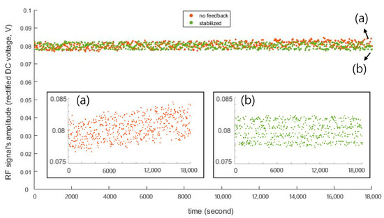
Figure 6.
Results of the amplitude of the RF signal for 18,000 s. (a) The amplitude of the RF signal without the control. The amplitude drifts from 79.50 to 81.34 mV. (b) The amplitude of the RF signal when the FPGA-based PI controller is used. The voltage does not drift. When the FPGA-based feedback controller is used, no overshoot occurs, and the settling time is less than 1 s.
Figure 7 shows fluctuation in the amplitude of the RF voltage with the baseline method and FPGA-based controllers. It represents that the performance of the new method is better than that of the method developed in the previous work. The standard deviations of the amplitude of the RF signal obtained by the ADC are 61.58 μV with the PI controller and 63.28 μV with the lag compensator, which are 0.099% and 0.102% of the amplitude, respectively. These results show that there is no drift. If a small drift persists, the lag compensator is more advantageous than the PI controller. Table 1 shows the fluctuation in the amplitude of the RF signal using the three different feedback controllers. This new method can reduce the fluctuation of the 1 MHz secular frequency of the trapped ion to less than 1 kHz. The voltages in Figure 7 and Table 1 are the outputs of the rectifier measured by ADC. When the helical resonator is not mounted on a vacuum chamber, the fluctuation in the amplitude of the RF signal is 1.806% with the use of a commercial universal PI controller, which is much greater than the 0.05% when the helical resonator is mounted on the vacuum chamber [13]. The fluctuation in the amplitude of the RF signal can be reduced more when using the FPGA-based feedback controller with the helical resonator mounted on a vacuum chamber than when employing the baseline method under the same conditions. By using the FPGA-based feedback control, we can also change the control method to suit the experimental conditions. Moreover, researchers can change the gains, set-point voltage, and input and output of a controller using a computer in this system. Remotely changing the conditions of the RF signal applied to the ion trap reduces the possibility of the changes that can be generated by researchers.
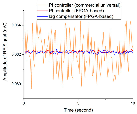
Figure 7.
The amplitudes of the RF signal using a commercial universal PI controller and the FPGA-based feedback controllers.

Table 1.
The fluctuations in the amplitude of the RF signal using a commercial universal PI controller and the FPGA-based feedback controller.
5. Conclusions
In this paper, we developed a method for reducing the fluctuation in the amplitude of the RF signal applied to ion traps using an FPGA-based feedback controller. This controller allows us to freely change the control method and feedback configuration. In particular, the voltage adders and subtractors were very effective in increasing the resolution. When the FPGA-based PI controller and lag compensator were used, the fluctuations in the amplitude of the RF signal were 94.510% and 94.359% lower, respectively, than the fluctuation when the commercial universal PI controller was used. If the helical resonator is mounted on a vacuum chamber, the fluctuation will be further reduced.
Supplementary Materials
The following are available online at https://www.mdpi.com/2076-3417/11/2/837/s1, Figure S1: A module of the field-programmable gate array (FPGA)-based feedback controller with the ana-log-to-digital converter (ADC), digital-to-analog converter (DAC), linear power suppliers, and printed circuit board (PCB), including the regulator, voltage adder circuit, and voltage sub-tractor circuit. Figure S2: A layout of the PCB, including the regulator, voltage adder, and voltage subtractor circuit. Figure S3: The output of the rectifier measured by the ADC when peak-to-peak voltage of 20 mV is added to the IF port of the frequency mixer and the FPGA-based feedback controller is switched off. Figure S4: The output of the rectifier measured by the ADC when peak-to-peak voltage of 20 mV is added to the IF port of the frequency mixer and the FPGA-based feedback controller is switched on.
Author Contributions
Conceptualization, Y.P., D.C. and T.K.; methodology, Y.P., D.C. and T.K.; software, Y.P., H.O. and S.Y.; validation, Y.P. and D.C.; formal analysis, Y.P. and D.C.; writing—original draft preparation, Y.P.; writing—review and editing, Y.P. and D.C.; visualization, Y.P.; supervision, D.C.; project administration, D.C. and T.K.; funding acquisition, T.K. and D.C. All authors have read and agreed to the published version of the manuscript.
Funding
This research was funded by Samsung Research Funding & Incubation Center of Samsung Electronics.
Institutional Review Board Statement
Not applicable.
Informed Consent Statement
Not applicable.
Data Availability Statement
Data are contained within the article.
Acknowledgments
This work was supported by Samsung Research Funding & Incubation Center of Samsung Electronics under Project Number SRFC-IT1901-09. Part of the validation of performance of the voltage divider was taken with the help from Myeongseok Seong at Seoul National University.
Conflicts of Interest
The authors declare no conflict of interest.
References
- Ballance, C.J.; Harty, T.P.; Linke, N.M.; Sepiol, M.A.; Lucas, D.M. High-Fidelity Quantum Logic Gates Using Trapped-Ion Hyperfine Qubits. Phys. Rev. Lett. 2016, 117, 060504. [Google Scholar] [CrossRef] [PubMed]
- Weidt, S.; Randall, J.; Webster, S.C.; Lake, K.; Webb, A.E.; Cohen, I.; Navickas, T.; Lekitsch, B.; Retzker, A.; Hensinger, W.K. Trapped-Ion Quantum Logic with Global Radiation Fields. Phys. Rev. Lett. 2016, 117, 220501. [Google Scholar] [CrossRef] [PubMed]
- Wu, Y.; Wang, S.-T.; Duan, L.-M. Noise analysis for high-fidelity quantum entangling gates in an anharmonic linear Paul trap. Phys. Rev. A 2018, 97, 062325. [Google Scholar] [CrossRef]
- Arrazola, I.; Plenio, M.; Solano, E.; Casanova, J. Hybrid Microwave-Radiation Patterns for High-Fidelity Quantum Gates with Trapped Ions. Phys. Rev. Appl. 2020, 13, 024068. [Google Scholar] [CrossRef]
- Gale, E.P.G.; Mehdi, Z.; Oberg, L.M.; Ratcliffe, A.K.; Haine, S.A.; Hope, J.J. Optimized fast gates for quantum computing with trapped ions. Phys. Rev. A 2020, 101, 052328. [Google Scholar] [CrossRef]
- Wineland, D.J.; Barrett, M.D.; Britton, J.W.; Chiaverini, J.; Demarco, B.; Itano, W.M.; Jelenkovic, B.; Langer, C.; Leibfried, D.; Meyer, V.; et al. Quantum information processing with trapped ions. Philos. Trans. R. Soc. A Math. Phys. Eng. Sci. 2003, 361, 1349–1361. [Google Scholar] [CrossRef]
- Zhu, S.-L.; Monroe, C.; Duan, L.-M. Arbitrary-speed quantum gates within large ion crystals through minimum control of laser beams. EPL Europhysics Lett. 2006, 73, 485–491. [Google Scholar] [CrossRef]
- Shapira, Y.; Shaniv, R.; Manovitz, T.; Akerman, N.; Ozeri, R. Robust Entanglement Gates for Trapped-Ion Qubits. Phys. Rev. Lett. 2018, 121, 180502. [Google Scholar] [CrossRef]
- Blumel, R.; Grzesiak, N.; Nam, Y. Power-Optimal, Stabilized Entangling Gate Between Trapped-Ion Qubits. arXiv 2019, arXiv:1905.09292. [Google Scholar]
- Gehm, M.E.; O’Hara, K.M.; Savard, T.A.; Thomas, J.E. Dynamics of noise-induced heating in atom traps. Phys. Rev. A 1998, 58, 3914–3921. [Google Scholar] [CrossRef]
- Lu, X.-J.; Ruschhaupt, A.; Muga, J.G. Fast shuttling of a particle under weak spring-constant noise of the moving trap. Phys. Rev. A 2018, 97, 053402. [Google Scholar] [CrossRef]
- Lu, X.-J.; Ruschhaupt, A.; Martínez-Garaot, S.; Muga, J.G. Noise Sensitivities for an Atom Shuttled by a Moving Optical Lattice via Shortcuts to Adiabaticity. Entropy 2020, 22, 262. [Google Scholar] [CrossRef] [PubMed]
- Johnson, K.G.; Wong-Campos, J.D.; Restelli, A.; Landsman, K.A.; Neyenhuis, B.; Mizrahi, J.; Monroe, C. Active stabilization of ion trap radiofrequency potentials. Rev. Sci. Instrum. 2016, 87, 053110. [Google Scholar] [CrossRef] [PubMed]
- Choi, T.; Debnath, S.; Manning, T.A.; Figgatt, C.; Gong, Z.-X.; Duan, L.-M.; Monroe, C. Optimal Quantum Control of Multimode Couplings between Trapped Ion Qubits for Scalable Entanglement. Phys. Rev. Lett. 2014, 112, 190502. [Google Scholar] [CrossRef]
- Snyder, D.T.; Pulliam, C.J.; Wiley, J.S.; Duncan, J.; Cooks, R.G. Experimental Characterization of Secular Frequency Scanning in Ion Trap Mass Spectrometers. J. Am. Soc. Mass Spectrom. 2016, 27, 1243–1255. [Google Scholar] [CrossRef]
- Paul, W. Electromagnetic traps for charged and neutral particles. Rev. Mod. Phys. 1990, 62, 531–540. [Google Scholar] [CrossRef]
- Leibfried, D.; Blatt, R.; Monroe, C.; Wineland, D. Quantum dynamics of single trapped ions. Rev. Mod. Phys. 2003, 75, 281–324. [Google Scholar] [CrossRef]
- Hong, S.; Lee, M.; Kwon, Y.-D.; Cho, D.-I.D.; Kim, T. Experimental Methods for Trapping Ions Using Microfabricated Surface Ion Traps. J. Vis. Exp. 2017, 126, e56060. [Google Scholar] [CrossRef]
- Harahap, C.R.; Hanamoto, T. Fictitious Reference Iterative Tuning-Based Two-Degrees-of-Freedom Method for Permanent Magnet Synchronous Motor Speed Control Using FPGA for a High-Frequency SiC MOSFET InverterMOSFET Inverter. Appl. Sci. 2016, 6, 387. [Google Scholar] [CrossRef]
- Ali, S.; Badar, J.; Akhtar, F.; Bukhari, S.S.H.; Ro, J.-S. Real-Time Controller Design Test Bench for High-Voltage Direct Current Modular Multilevel Converters. Appl. Sci. 2020, 10, 6004. [Google Scholar] [CrossRef]
- Pagano, G.; Hess, P.W.; Kaplan, H.B.; Tan, W.L.; Richerme, P.; Becker, P.; Kyprianidis, A.; Zhang, J.; Birckelbaw, E.; Hernandez, M.R.; et al. Cryogenic trapped-ion system for large scale quantum simulation. Quantum Sci. Technol. 2018, 4, 014004. [Google Scholar] [CrossRef]
- Hahn, H.; Zarantonello, G.; Schulte, M.; Bautista-Salvador, A.; Hammerer, K.; Ospelkaus, C. Integrated 9Be+ multi-qubit gate device for the ion-trap quantum computer. npj Quantum Inf. 2019, 5, 1–5. [Google Scholar] [CrossRef]
- Gandolfi, D.; Niedermayr, M.; Kumph, M.; Brownnutt, M.; Blatt, R. Compact radio-frequency resonator for cryogenic ion traps. Rev. Sci. Instruments 2012, 83, 084705. [Google Scholar] [CrossRef] [PubMed]
- Nice, N.S. Control Systems Engineering, 6th ed.; John Wiley & Sons: Hoboken, NJ, USA, 2011; pp. 455–532. [Google Scholar]
Publisher’s Note: MDPI stays neutral with regard to jurisdictional claims in published maps and institutional affiliations. |
© 2021 by the authors. Licensee MDPI, Basel, Switzerland. This article is an open access article distributed under the terms and conditions of the Creative Commons Attribution (CC BY) license (http://creativecommons.org/licenses/by/4.0/).