Review

Drilling Fluid and Cement Slurry Design for Naturally Fractured Reservoirs

Faculty of Mining, Geology and Petroleum Engineering, University of Zagreb, 10000 Zagreb, Croatia
*
Author to whom correspondence should be addressed.
Appl. Sci. 2021, 11(2), 767; https://doi.org/10.3390/app11020767
Submission received: 10 December 2020 / Revised: 31 December 2020 / Accepted: 8 January 2021 / Published: 14 January 2021
(This article belongs to the Special Issue Fractured Reservoirs)

Abstract

:
For years, drilling engineers have been faced with the challenge of drilling wells through naturally fractured reservoirs that are present around the world. During drilling, the pressure at the bottomhole of a well is frequently intentionally higher than formation pressure, which can result in the loss of mud in surrounding rocks. During well cementing, the bottomhole pressure is even higher than it is during drilling, because the cement slurry density is higher than the density of the mud. Therefore, if natural or induced fractures in the surrounding rocks are not plugged during drilling, the cement slurry can be lost to them, reducing their permeability which is undesirable in the case of a pay zone. To prevent the loss of circulation and the related consequences, it is necessary to apply good drilling and cementing practices and to use adequate methods and carefully selected materials for plugging the loss zones. The aim of this article is to give an overview of the preventive and corrective methods that can be applied in drilling and cementing through fractured zones as well as improvements in drilling and cementing technology to avoid lost circulation issues (e.g., aerated drilling fluid, casing while drilling, managed pressure drilling, expandable tubulars, lightweight cement slurries, etc.).

1. Introduction

Oil and gas companies very often face the phenomenon of fluid loss during the drilling process. The loss of large volumes of whole mud to the formation (lost circulation) has historically been the root cause of well control problems and high mud costs. Many drilling hazards such as hole collapse, stuck pipe because of poor cutting removal, and even blowouts have been the result of lost circulation. In addition, lost circulation may cause extensive formation damage from lost circulation remedial treatments. Based on an extensive review of literature, Elkatatny and co-authors (2020) found that lost circulation costs 10–20% of the cost of drilling high pressure high temperature wells and 90% of these losses occur in fractured formations [1]. The negative consequences are magnified greatly in a deep-water environment [2].
The causes of fluid loss may be the presence of natural or induced fractures, cavernous zones, or high permeability of the matrix [3,4,5]. Natural fractures may occur in any type of formation. If drilling is continued and more natural fractures are exposed, a complete loss of returns may be experienced [3]. Naturally fractured reservoirs exist throughout the world and contain significant amounts of hydrocarbon reserves. The presence of natural fractures in a reservoir is a problem during drilling and cementing but is desirable from the aspect of well productivity. Natural fractures improve production by enhancing the effective permeability of rocks greatly by connecting pores together but can complicate drilling and cementing operations as well as reservoir stimulation. Induced fractures are principally those produced in the surrounding rocks by the fluid pressure applied within a well bore [5].
Induced fractures during drilling are undesirable because large amounts of the fluid can be lost to the surrounding rocks. However, after drilling and well completion, in some reservoirs, fractures are intentionally induced to increase hydrocarbon flow.
A large volume of drilling fluid loss into the formation poses severe threats. Although different solutions have been recommended to avoid any kind of fluid loss, the oil and gas industry is still facing difficulties in determining and detecting these problems [6].
Lost circulation is most commonly divided into four types based on the amount of the loss rate (severity of the losses), as follows, seepage loss, partial loss, severe loss, and total loss [7,8], and can take place in both static (static loss rate) and dynamic conditions (flowing loss rate) [9,10,11].
According to the type of losses the industry proposes various precautions that should be applied such as maintaining Equivalent Circulating Density (ECD) by decreasing the mud density as well as by reducing the values of rheological parameters and mud flow rate, adding lost circulation materials (LCMs) to the mud in order to strengthen the formation or the implementation of advanced drilling techniques like Managed Pressure Drilling (MPD), Underbalanced Drilling (UBD), or Casing while Drilling (CwD) [12,13,14,15]. Compared with conventional drilling techniques, for drilling formations below hydrostatic pressure (UBD) low density media can be used as a drilling fluid, such as air, nitrogen, mist and foam so that in underpressure conditions, it causes an inflow of the formation fluid into the well and reduces mud loss [15,16,17].
Controlling severe to total losses in naturally fractured/vugular formations is still a challenge, particularly in carbonate formations in which conventional particulate Lost Circulation Materials (LCMs) might not be effective although they have been widely used to avoid or stop losses [18].
A variety of materials and techniques have been developed to stop lost circulation and stabilize a wellbore [3,19,20,21,22,23,24,25].
For years, classical LCMs have been classified into four categories (fibrous, flaky, and granular or a mixture of all three), but Alsaba et al. (2014) proposed a new classification based on their appearance and application that considers conventional and new LCM materials (acid/water soluble, high fluid loss squeeze, swellable/hydratable combinations, and nanoparticles) [4].
Savari et al. (2016 and 2020) presented laboratory evaluation methodology, test results, and field application of the combination of a high fluid loss squeeze (HFLS) and reticulated foam LCM that could seal a laboratory-simulated fracture/slot size of 9800 microns [26] and 31,700 microns [18]. They used a permeability plugging apparatus (PPA) with minor modifications to evaluate the LCM combination mixed in different bases (water, diesel, mineral oil, CaCl2 brine and CaBr2 brine). The combination of HFLS and reticulated foam LCM can provide a technically efficient alternative to particulate solutions for managing severe to total losses in the case of uncertain fracture sizes in naturally fractured/vugular formations [18].
Bychina et al. (2017) presented a comprehensive analytical model that can be used for different drilling fluids (Newtonian fluid, Bingham fluid, dilatant fluid, and pseudoplastic fluid) [6]. The model considers a linear fracture deformation with pressure change and leak-off from the fracture into the formation which leads to a more accurate estimation of the volume of drilling fluid loss than the pre-existing models. They concluded that the pressure differential is the driving force behind the fluids leaking into the fracture. The fluid rheology also dictates the rate of fluid loss into the formation. The drilling fluid loss increases as the value of flow behavior index and consistency index decreases [6]. Mud loss is influenced by many factors that make finding an analytical solution with acceptable accuracy very difficult or impossible, so in recent years, researchers have been trying to find a new method which can be successfully applied for the prediction of lost circulation zones by applying artificial intelligence (Artificial Neural Network (ANN)) [1,27,28,29,30,31,32].
In recent years, more and more wells are being drilled in complex reservoir conditions so there is need for the improvement of drilling mud properties in order to successfully and safely drill wells. Researchers started to investigate the possibility of applying nanotechnology, especially nanoparticles added to drilling mud for drilling through shales. Conventional drilling additives are too large to seal the nano-sized shale, in contact with water-based drilling muds, shale swells which results in wellbore instability. The results showed that the addition of clay/SiO2 and TiO2 nanoparticles improved the rheological properties [33,34]. In addition to rheological modification, nanoparticles (size 1 to 500 nm) added in a concentration up to 1 wt% are shown to be effective for reducing fluid loss [35].
With this review manuscript, we tried to collect and organize all the available information related to problems that arise during drilling through naturally fractured formations. Different authors through their own studies and research sought to cover specific problems related to lost circulations in certain fractured formations. In most cases, these studies and research provide valuable information for problem solving on the same field and on other fields with similar conditions, but do not provide a broad picture. From this point of view, we tried to collect all this relevant information, and give readers one comprehensive review of the lost circulation problems and solutions for drilling through naturally fractured formations. Along with a detailed analysis and quantification of fluid losses in naturally fractured formations, as well as an overview of the available techniques and technology solutions, for the first time, we also endeavored to comprehensively view and compare the loss circulation problems in drilling and well cementing operations.
Based on an extensive analysis of the literature, it can be concluded that there is no universal method to solve the problem of circulatory loss. Therefore, the selection and design of the process should be based on the specific requirements of an individual well.

2. Determining the Location of the Thief Zone and the Classification of Fluid Loss

Highly permeable, porous, fractured, and cavernous formations encountered during drilling can be a zone of fluid loss, often called a thief zone. Determining the depth of the thief zone is important in order to take preventive or corrective measures to prevent or stop further fluid loss.

2.1. Location of the Thief Zone

The thief zone can be at the bottom or above the bottom of the hole depending on the observed changes in conditions during drilling (see Table 1).
An accurate estimation of the loss zone location allows for the application of the treatment directly at the point of loss, resulting in high efficiency and shorter non-productive rig time. Various tools and methods are used to determine the location of the loss zone and avoid lost circulation such as (1) Real-time geomechanical analysis, (2) Pre-drill geological analysis, (3) Pressure transducer surveys, (4) Open hole logs, (5) Hot wire surveys, (5) Radioactive transducer surveys, (6) Temperature surveys, (7) Spinner surveys, (8) and Oxygen activation and water flow measurements tools [2,5,37,38,39,40,41]. However, some of these methods are difficult to be apply due to financial issues and lack of technology, while other methods are not accurate in the prediction of thief zones. More recently, artificial intelligence techniques such as radial basis function (RBF) and a support vector machine (SVM) have been used to predict lost circulation zones [42].

2.2. The Classification of Fluid Loss

The best approach to cure lost circulation is to assess the severity of fluid loss (drilling fluid or cement slurry) in the loss zone and match the remedial material and technique to it, both in terms of the size of the material and its function. According to the severity of fluid loss, lost circulation can be classified into four categories: seepage loss, partial loss, complete loss, and severe complete loss [5]. The severity of loss is best determined by the amount of loss and the static mud column height (see Table 2).
From the data shown in Table 2, it can be concluded that during drilling through fractured formations, and depending on the size of the fracture, partial losses, and even more often, complete (total) mud losses can occur.
Different classifications can be found in literature according to the severity of losses and with different values of the loss rate (see Table 3). Also, the rate of loss is stated differently depending on the conditions as static loss rate (occurs in static conditions) and flowing loss rate (occurs in dynamic conditions) [4,9,11,43,44]. Some authors and companies also base the distribution of losses on the type of mud and state lower values for oil-based muds (OBM) than for water-based muds (WBM) [45,46].
Based on the data shown in Table 3, it can be concluded that most authors and companies agree on the definition of seepage (minor losses; <1.6 m3/h) and total losses (no drilling fluid returns to the surface). Defining partial (moderate/medium losses; from 1.6 to even 80 m3/h) and severe (massive/complete; from 3.2 to more than 80 m3/h) losses differs significantly.

3. Prediction of Lost Circulation

For the successful drilling of a well through naturally fractured reservoirs to the target depth, predicting the loss zone using artificial intelligence can be of great help [1,27,28,29,30,31,32,51].
Moazzeni et al. (2010) tried to predict lost circulation in different areas in Maroun oilfield using drilling daily reports from 32 drilled wells. They used artificial neural networks to estimate the quantity and quality of fluid loss for each day using recorded data in that day or previous days. According to their research, the network precision in cases of low mud loss is very good, but in cases of very severe losses, it is significantly worse. The reason for that can be data inconsistency of input parameters. Also, many parameters which can affect lost circulation are not considered with the input data [28].
Toreifi et al. (2014) designed two models using Artificial intelligence and data collected from 38 wells located in Maroun oilfield, in the Middle East. Both models were developed by a modular neural network for the prediction of the amount of mud loss in any coordinates of a field using operational and geological data. They concluded that the neural network had an accurate prediction of lost circulation in the Asmari formation of the Maroun oilfield and recommended utilizing an artificial neural network just for the field under study [32]. Unfortunately, the model is applicable only in a specific area, so other fields should utilize a new neural network [52].
Efendiyev et al. (2016) studied the impact of petrophysical rock properties on lost circulation in terms of lack of information. Their research was performed by cluster analysis (FCM-method). Cluster-analysis or automatic classification problems are widely used in various fields, including in the petroleum industry [51].
Solomon et al. (2017) applied an artificial neural network to predict the fracture width and determine the particle sizes of the loss prevention materials. Their results were compared with existing 2D fracture models and benchmarked against experimental results published in the literature. They showed that the key parameter for determination of adequate loss prevention materials are rock properties. Also, the application of an artificial neural network in the future should contain a more robust and localized data sets [27].
Far and Hosseini (2017) studied the effect of mud weight, wellbore depth, pump pressure, and flow rate on lost circulation in the UBD of the Asmari formation, Southwest Iranian fields, using drilling data and an artificial neural network. In their research, they chose three wells with the most, moderate, and without lost circulation. They showed that the amount of lost circulation can be estimated using the created neural network with very good accuracy. Also, lost circulation has a direct relation to pump pressure and a reverse relation to flow rate [31].
Abbas et al. (2019) presented a study that can be used to predict a lost circulation occurrence by using artificial neural networks and Support Vector Machine (SVM). The field datasets were collected from 385 wells drilled in southern Iraq. The data included drilling operation parameters, formation type, lithology of the rock, and drilling fluid characteristics. According to their results, lithology type, mud weight, and flow rate had the most impact on lost circulation [30].
Elkatatny et al. (2020) showed that an artificial neural network (ANN) and a Functional Network (FN) can be used to predict loss zones with high accuracy. They used real-time drilling sensors and obtained data of real-time surface drilling parameters to predict the zones of lost circulation. According to their research, artificial intelligence techniques were tested by using data from one well to predict lost circulation zones with high precision. Also, their method is simple to use because the prediction of loss zones is determined from only the mechanical surface drilling parameters which are easily available for each well [1].
Abbas et al. (2020) used drilling data of previously drilled wells in Southern Iraq (448 cases) to establish which drilling parameters have the greatest impact on the risk level of lost circulation while drilling. Data was obtained from daily drilling reports, daily mud reports, final well reports, and master logs. They showed that the lost circulation rate can be increased by increasing the flow rate, by raising the ECD. Also, an increased rate of penetration (ROP) results in insufficient hole cleaning and negatively affects the ability to estimate losses. Other parameters that can leads to an increase in mud loss rate is mud weight because of its influence on hydrostatic pressure calculations. Their results showed that statistical analysis can be used to match the predicted and actual loss rate [29].

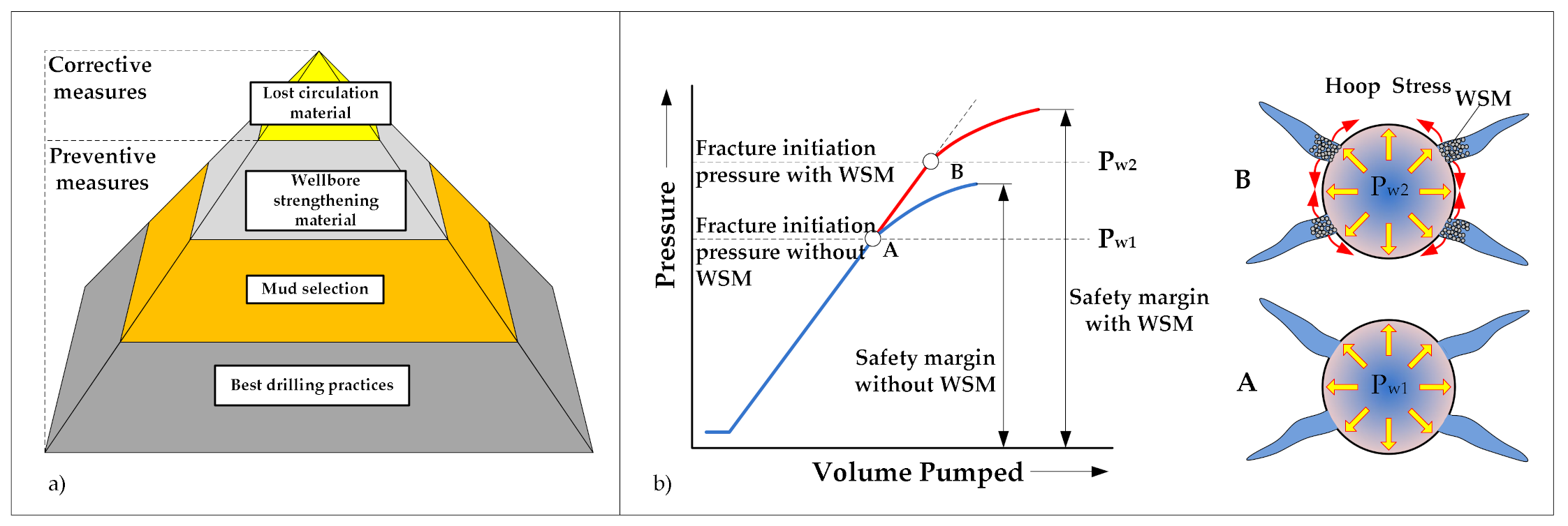
4. Preventive and Corrective Lost Circulation Measures

The way that lost circulation measures or methods are applied could be classified based on the time these measures were implemented, whether they were applied before (preventive measures; pretreatment and/or borehole stress treatments to strengthen the wellbore) or after (corrective measures; mitigating lost circulation and, where possible, providing additional wellbore strength) the occurrence of a lost circulation event [4,8,38,53,54]. The preventive approach to mitigate the loss of circulation is easier than the corrective approach.
The hierarchy in the application of preventive and corrective (remedial) measures (a) and the mechanism of wellbore strengthening are shown in Figure 1.
Wellbore strengthening (or creating of stress cage) is a preventive treatment and can be used to efficiently plug and seal fractures while drilling before losses occur [53,55]. The sealing of fractures during drilling is achieved by maintaining a certain concentration of bridging material (Wellbore Strengthening Material (WSM), e.g., deformable graphite, granular, cellulosic material, blends) in the mud or by using pills to strengthen sections that have already been drilled, but without losses. Wellbore strengthening is a method for increasing the fracture resistance by increasing the hoop stress in the near wellbore area and consequently the ability of the wellbore walls to withstand higher dynamic pressure (higher ECDs) without causing mud loss.

4.1. Preventive Measures to Avoid Lost Circulation during Drilling

The preventive approach involves managing the loss of circulation by planning in advance and possibly stopping its occurrence. Preventive measures must be applied when the mud loss exceeds 0.16 m3/h which is the maximum allowable loss of fluid [41]. This loss can be measured in the pits at the surface. In all situations where a loss zone is expected, preventive measures should be taken by adjusting the mud properties and adding a circulating material (LCM) to the mud. In addition, it is extremely important to perform the leak off test (LOT) and Formation Integrity Test (FIT) to limit the possibility of lost circulation.
The complete prevention of lost circulation is impossible during drilling through naturally fractured, cavernous or high permeability zones, but it is possible to limit the loss of circulation by taking certain precautions, especially those that avoid the occurrence of induced fractures. The most efficient approach to prevent losses is keeping the wellbore pressure equal to or very close to the formation pressure. Preventive measures are shown in Table 4 and include controlling the Bottomhole Pressure (BHP), Wellbore Pressure Containment Improvement (WPCI), running intermediate casing in the transition zones, setting expandable tubulars, and wellbore strengthening [5,53,55,56,57].
Drilling technologies that can prevent circulation loss are briefly described below.

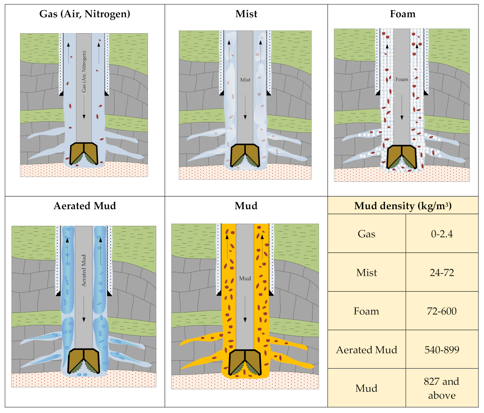
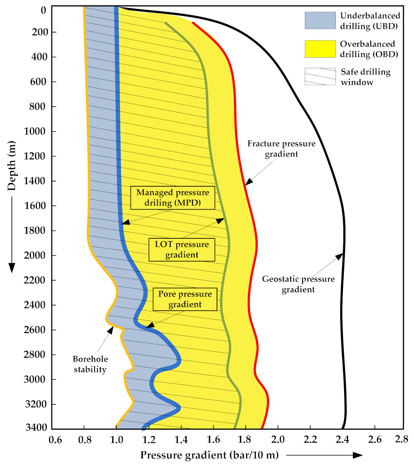
4.1.1. Underbalanced Drilling (UBD)

During conventional drilling, the pressure of the mud column in the wellbore is higher than the pore pressure which represents overbalance conditions. In some cases, especially during drilling through highly depleted reservoirs, naturally fractured, vugular, and highly permeable formations, due to the low pore pressure, losses to the formation can occur. Therefore, mud pressure in the wellbore can be held below the pore pressure (underbalanced drilling) which allows the formation fluid to flow into the wellbore [58,59].
To achieve circulating densities lower than the pore pressure, the use of lighter fluids is required, such as air, mist, foams, and aerated mud foam with back pressure (see Figure 2) [15,16,17].
In some cases, underbalanced drilling is the only available drilling technology [16], and it is more complex than conventional drilling or managed pressure drilling due to the presence of multi-phase fluid flows (see Figure 2). The pressure window in Overbalanced Drilling (OBD) is between the pore pressure and the fracture pressure gradient, while in underbalanced drilling (UBD) it is between the borehole stability pressure and the pore pressure (Figure 3) so, in some situations, the size of the windows will determine the appropriate drilling technology [60].
A significant benefit of underbalanced drilling is that depleted or fractured reservoirs can be drilled with minimizing loss of circulation which has an impact on mud cost, and thus increases the ROP, bit life, well productivity, etc. [61]. However, during underbalanced drilling there is a need for additional equipment and procedures (higher pressure rotating control heads, four-phase separators etc. [16]), such as the lack of customized rigs and additional crew, so sometimes it is not technically feasible [62].
According to Ashraf et al. (2020), recent attempts to drill new wells in the Pakistan gas field Qadirpur were extremely unsuccessful because of the massive lost circulation resulting in severe reservoir damage and zero production. By applying UBD, the re-entry well-X through highly depleted and fractured reservoir formation was drilled without problems and the high cost of complete lost circulation was eliminated [15].

4.1.2. Managed Pressure Drilling (MPD)

Conventional drilling of fractured or depleted formation as well as deep formation in a high pressure and high temperature environment usually can be very difficult because of the small difference between pore pressure and fracture pressure at a certain depth. In depth offshore conventional drilling activities, this means the installation of more casing strings than necessary in order to reach the total depth [63]. These circumstances impose the need for better optimization and a precise control of annular pressure to prevent problems like well control issues, lost circulation, or a stuck pipe [13,14]. Furthermore, to ensure safety and trouble-free drilling through a formation with narrow drilling margins, it is necessary to maintain the appropriate annular pressure in static and dynamic conditions. According to the International Association of Drilling Contractors (IADC), Managed Pressure Drilling (MPD) represents an adjustable drilling technique for the precise control and maintenance of the annular pressure profile throughout the wellbore. Due to specific downhole conditions, a managed pressure technique except for drilling also can be utilized for different operations which follow the drilling process (liner running, cementing, wireline operations, tripping, etc.) [64,65]. This relatively new technique combines the low drilling fluid density with the additional pressure applied in the annular space on the surface and all with the purpose of the maintenance annular pressure profile within a safe drilling window. For drilling through zones with a total loss of the drilling fluid, the application of Mud Cap Drilling (MCD) can be very useful. Mud Cap Drilling represents a special variation of the managed pressure drilling and the includes following methods: Floating Mud Cap Drilling (FMCD), Pressurized Mud Cap Drilling (PMCD), Dynamic Mud Cap Drilling (DMCD), and Controlled Mud Cap Drilling (CMC) [63,66]. Aside from the mentioned MCD, there are other variations of managed pressure drilling such as Constant Bottomhole Pressure (CBHP), Dual Gradient Drilling (DG), and Return Flow Control (RFC) or the Health, Safety, Environment (HSE) Method. Depending on the selected managed pressure drilling method, a drilling rig must be equipped with additional equipment like a rotating control device (RCD), a non-return valve (NRV), chock gates, sliding plates, shuttles, a continuous circulation system (CCS), a continuous circulation valve (CCV), or a backpressure pump. MPD was applied for the drilling of 7 wells in the carbonate naturally fractured reservoir of East Siberia where conventional drilling of a highly fractured zone was accompanied with intensive mud losses, thus over 50% of drilled wells in the oilfield could not reach the final depth. Compared to conventional drilling, the application of MPD resulted in a 24% decrease in loss of drilling mud, a 7% increase in the average rate of penetration, and a 30% increase in average productivity. At the same time, the average cost per meter for MPD was 14% higher than conventional ones [67].

4.1.3. Casing While Drilling (CwD)

Casing while drilling (CwD) (also known as Casing Drilling—CD) is a relatively novel method where casing is used instead of drill pipes and drill collars. This type of well drilling is recognized as one of the most effective and cost-saving ways to drill and complete a well [68], as it provides the simultaneous drilling and casing of a well. Casing drilling eliminates costs associated with drill pipes, with a much greater benefit of eliminatingpotential problems that can occur during drill pipe tripping operations. These include circulation loss, wellbore stability problems and well control incidents [69], which can lead to complex and expensive operations. Also, this method enables continuous mud circulation which is a safer option than phases of static conditions without circulation, which is the case in conventional drilling.
The main advantages of this method are a reduction of drilling non-productive time, a reduction of lost circulation in problematic zones and overcoming wellbore stability problems [70,71,72,73]. The diameter of the casing is considerably larger than the diameter of drill pipes used in conventional drilling, which results in a smaller area for mud flow in the annulus. In these conditions, an effect known as plastering occurs and it enhances wellbore stability. The ratio of the outer diameter casing to hole size is certainly the primary factor for the occurrence of the plastering effect which is believed to be more than 0.75 [70]. Drilled cuttings are crushed to finer particles between the casing and the wellbore during contact due to limited annular clearance [72], which results in a larger particle size distribution profile than during conventional drilling [74]. A higher mud particle concentration and size distribution helps in bridging and fracture closure through the plastering effect [75], because finer sized cuttings are smeared into the wellbore face by the mechanical contact of the large diameter casing with the borehole walls [74]. This creates a thin, but almost impermeable mud cake that sets up a barrier and successfully prevents fluid loss, which has been proven in field trials [72]. Consequently, the plastering effect that occurs during casing drilling increases the fracture gradient and improves the wellbore strengthening [76].

4.1.4. Solid Expandable Tubulars (SET)

Solid Expendable Tubular (SET) technology was commercially applied for the first time in November 1999 with one main goal: to reduce the cost of drilling and the completion of a well in shallow water in the Gulf of Mexico [77]. According to Cameron et al. (2013) and Park et al. (2015) solid expandable technology includes a cone movement upward and downward through installed tubular casing under the action of force or pressure [78,79]. In the case of a liner string, the possible expansion is usually in the range between 5% and 18%, but there is also successful operation with an expansion higher than 20%. The mentioned cost reduction is possible in two ways. Firstly, this technology allows for the drilling of smaller diameter wellbores and the utilization of a smaller diameter of expandable casing string, significantly reducing the cost of drilling as well as the associated cost of casing and cementation. However, this technology has a very wide application in solving different problems related to exploration and production activities and associated costs such as extension of the casing shoe, loss of wellbore integrity, control of lost circulation, overpressured or unstable zones during drilling, covering old perforation intervals or damaged casings, etc. [77,80]. The latest development in solid expendable tubular technology allows for the construction of a monobore wellbore as well as the installation of multiple clad/unclad liners to cover problematic zones in a hole with the same internal diameter. A clad liner contains external seals and other external attachments which are used for covering the lost circulation and depleted zone in an an open hole section [81].

4.2. Corrective Measures to Mitigate Lost Circulation during Drilling

When drilling through fractured and vuggy carbonate, a preventive approach is not always effective, and a corrective approach should be taken. This is done using both conventional lost circulation materials (LCMs) and different types of specially designed plugs based on cement, cross-linked polymers, a mixture of organic products or other materials with or without conventional LCMs as shown in Table 5 [1,3,4,22,82,83]. In order to seal natural fractures or induced fractures, lost circulation materials are added continuously to the drilling fluid or spotted as a concentrated LCM pill [4]. According to Fomenkov et al. (2019) in Volga-Urals region, many lost circulation control techniques such as a new special-purpose thixotropic cement slurry, foamed cement plugs, cement-bentonite-diesel slurries, fibrous bridging materials, variable-sized bridging agents, shredded polyethylene, detachable plastic tubulars, expandable-profile liners, felted cloth, cord fiber, etc. are currently used [84]. The total loss of circulation is almost always treated with remedial procedures and techniques.
Lost circulation materials (LCM) can be added to the mud before losses occur to prevent mud loss, but they can also be added to mud in the form of a pill after losses occur to plug the loss zone.
The selected LCM should go through restrictions in Bottom Hole Assembly (BHA). Coarse and extra-coarse grades of LCMs should always be spotted through a bypass circulation tool or open-ended pipe to avoid the potential plugging of downhole tools or bit nozzles.
The choice of size, type, and concentration of LCM is extremely important for plugging/bridging pores and fractures, so that the material penetrates deep enough into the rocks and does not remain on the rock surface, because in this case, after re-establishing circulation, mud loss will occur again [5,10,46,83,85].
High-resiliency graphite bridging agents (median particle size (d50): 300–350 microns) provide enhanced bridging and sealing of natural or induced fractures, and can be used to control loss of fluid in partial to severe lost circulation zones. The recommended treatment range in the entire system is 29 to 70 kg/m3, and for partial losses (1.6 to 16 m3/h) is 57 to 143 kg/m3 in spotted pills. Highly permeable formations such as fractured carbonates and conglomerates may require additional pills in conjunction with lost circulation materials of various sizes. Granular, shear-resistant particulates (medium: 800–1500 microns, coarse: 1500–2280 microns, and extra-coarse: 2050–4300 microns) are useful for lost circulation control and wellbore strengthening when drilling ultrahigh-permeability formations or when fractures up to 4 mm are encountered. They can be used in all types of drilling fluids. The recommended treatment range for spotted pills is 29 to 57 kg/m3. Typical concentrations include a range of blends (e.g., blends of graphitic material and ground nut shells, sized marble or sized marble and cellulosic material of nominal median particle size (d50): 500–600 microns) for continuous particle addition to the circulating drilling fluid when drilling a formation known to have losses is from 35 to 57 kg/m3, and for remedial lost circulation treatments from 85 to 200 kg/m3, depending on the severity of the losses. Blends are designed for loss zones with maximum openings of at least 1200 microns [86].
In many cases, the success or failure of a LCM largely depends on the decisions made and methods employed when using the LCM. Because of that, controlling circulation loss during drilling with particulate and/or fibrous material requires a complete engineered approach that includes borehole stability analysis, equivalent circulating density modelling, leak-off flow-path geometry considerations, drilling fluid type, and LCM material selection to help minimize pressure effects on the ECD, on-site monitoring using pressure while drilling, and a timely application of LCM and treatments [3,4,8,53].
The effectiveness of each particulate LCM treatment can be determined by a slot disc test performed in the laboratory. The laboratory testing was conducted with slots which have different fracture widths ranging from 1 to 2 mm [87], 1, 0.5 and 0.2 mm [88], 3 mm [89], 2 mm [90], and 3 mm [91]. The drilling fluids containing lost circulation materials are forced to pass through the selected disc under HPHT conditions, and the tested LCM is evaluated by both the total 30-min fluid loss and the time it takes to plug a slot disc [4]. Particle Size Distribution (PSD) analysis is also used for proper particle size selection based on the pore size or the estimated fracture width [53].
Figure 4 shows an example of quality and appropriate fracture plugging with conventional LCMs. If the fractures are blocked during the drilling phase, the primary cementing will be performed without losing the cement slurry. Otherwise, the loss of the cement slurry into inadequately plugged fractures can be expected. Spotting a pill of deformable graphite prior to running casing and cement slurry is good practice if there is a zone exposed that is unlikely to support the column of the cement slurry [46].
Treatments with conventional particulate LCMs may not be effective for plugging/bridging very large fractures (larger than 2000 microns) and then it is necessary to use chemical sealants with or without particulate LCMs [4,53].
To cure severe or total losses, better results are achieved by placing crosslinked polymers or cement plugs in the loss zone than by placing LCM pills and it is more likely that losses will not occur in the continuation of drilling or during primary cementation [2,8,9,22,82,92,93,94,95,96]. Cross-linked polymer fluid with a specific setting time can be pumped through the existing bottomhole assembly (bit nozzle size greater than 11.11 mm (14/32 in)) without losing time associated with tripping and mixing conventional LCM [22]. Biodegradable, organic cross-linked polymer plug, or pill can be used in sensitive reservoirs with minimal formation damage because, with time and temperature, will break back to a fluid state and be able to circulate out of the wellbore [22].
Figure 5 shows the loss of mud during drilling (a), the pumping and spotting of a thixotropic cement slurry into thief zone b) and the situation in the well after hardening of the cement slurry into set cement of sufficient strength to withstand various stresses in the future (c).

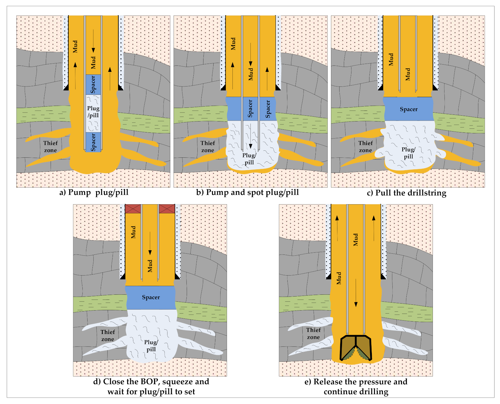
4.3. The Procedure of Spotting and Squeezing the Plug in the Thief Zone

If mud loss occurs during drilling, it is first necessary to determine the severity of the losses and the location of the loss zone so the pill/plug can be efficiently placed where needed. After that, the implementation of corrective measures is approached. To cure severe or total losses in the case of fractured formations, different types of plugs/pills can be used, including cement, cement-bentonite, reverse gunk, cement-gilsonite, diesel-oil-bentonite-cement, thixotropic cement, a thermally activated oil gelling pill, a polymer-based cross-linked pill (PCP), a chemically activated cross-linked pill (CACP), or a High-Fluid loss, High-Strength (HF/HS) pill) [1,19,22,23,36,91,97]. The generally recommended procedure of their pumping and squeezing into the thief zone is shown in Figure 6 and may vary slightly depending on the type of pill/plug used. If the zone of mud loss is also a production zone, pill/plug LCMs should be used that will not cause permanent damage to the production zone, i.e., those that are degradable or soluble in acid.

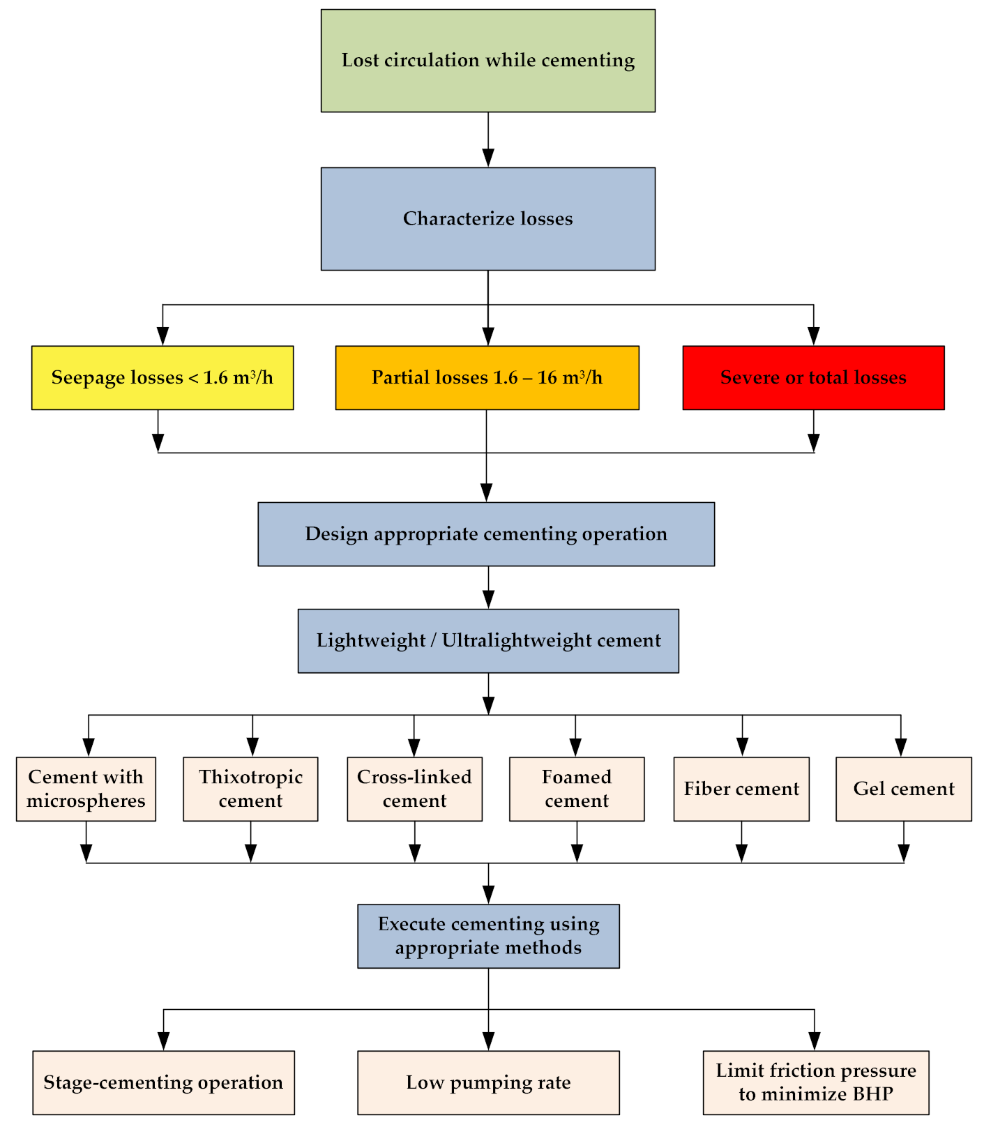
5. Lost Circulation While Cementing through Naturally Fractured Reservoirs

The risk of losses is greater in the cementation phase than in the drilling phase. Generally, the values of density and rheological properties of a cement slurry are higher than the values of these parameters for a drilling fluid while the flow area is smaller. Therefore, due to the higher equivalent circulation density (ECD) and the smaller clearance between the casing and the open hole, it can be expected that the dimensions of the existing fractures will increase during cementation, which will lead to the loss of the cement slurry. Extreme circulation losses during cementing operations pose a major threat to successful well cementation.
The loss of circulation during primary cementing results in reduced annular space coverage, casing corrosion, reduced safety, poor zonal isolation, and often requires the application of some remedial cementing techniques.
To prevent the loss of a cement slurry, mud loss zones should be sealed by known methods before cementation. If this is not possible, it is recommended to: (1) maintain the pressure during cementation below the maximum equivalent mud density in the circulation (ECD) and (2) place the LCM in the loss zone. Maintaining pressure during cementation below the maximum equivalent mud density in the circulation (ECD) can be achieved by decreasing the cement slurry density, reducing the height of the cement slurry column or limiting the flow resistance during the flow of the cement slurry through the annular space by adjusting its rheological properties. In addition, LCM can be used as a spacer in front of the cement slurry or LCM can be added to the cement slurry. Furthermore, special additives can be used that give the slurry thixotropic properties so that during the penetration of the cement slurry into the loss zone, its speed decreases and the gel structure develops and eventually the zone plugs due to increased resistance to the flow of the thixotropic cement slurry. Mofunlewi and Okoto (2016) described an engineered cement spacer fluid that can cure moderate to total losses in permeable and fractured formations [98]. This spacer contains hydrophobically modified polysaccharides which form micelles in water. By increasing the differential pressure, the micelles are compressed and absorbed to form a layer of adsorbed micelles that forms an impermeable seal at maximum differential pressure. The layer of adsorbed micelles transforms again into water-dispersed micelles at pressure relaxation or inflow from the formation, so damage to the formation is minimal. Therond et al. (2018) performed a comprehensive field analysis to understand lost circulation initiation during different phases of drilling and primary cementing. They analyzed 40 offshore well sections (18 casing and 22 liners) from four different locations (the Gulf of Mexico, the United Kingdom, Angola, and Azerbaijan) that reported losses prior to, or during, primary cementing operations. The results of the research showed that losses were commonly induced while running casings (in 42% of the cases) or pre-cement job mud circulation (in 48% of the cases), but rarely during cement placement (in 5% of the cases) and suggested that if losses are prevented during drilling, running casings and pre-job circulation, then the probability of having losses during cementing is significantly reduced [48]. The fact that in 95% of the cases losses were initiated prior to cementing, even though cementing ECDs are typically higher than drilling ECDs, is contrary to what is often perceived. Further, the results of the field study showed that the cement slurry was able to reduce the lost circulation rate when losses were severe or total prior to cementing (in more than 59% of cases) but this was not the case when partial or seepage losses occurred. A cement slurry possesses inherent wellbore strengthening capabilities [48].

5.1. Cement Slurry and Set Cement Properties

The importance of cement slurry design is especially pronounced in situations of placing a cement slurry in fractured zones or zones of low pore pressure, because then one can expect a loss of the cement slurry in the surrounding rocks. Since each well is unique according to its characteristics, which include pore pressure, fracture gradient, bottomhole temperature, and bottomhole pressure, physical properties of the formation, wellbore deviation, annular space clearance, and other parameters, the properties of the cement slurry should be appropriately optimized according to the requirements of each well.
The properties of a cement slurry such as density, viscosity, and thickening time are the most important parameters and should be considered when designing a successful primary cementing operation.

5.1.1. Cement Slurry Density

In some cases, it is sufficient to reduce the density of the cement slurry to prevent circulation losses. A reduction in cement slurry density during the cementation of casings is achieved by adding light-weight materials to the cement slurry or by foaming the cement slurry [20,44,49,84,99,100,101,102,103].
Critical design factors must be established to minimize dynamic pressure or equivalent circulating density (ECD) which is exerted in the potential thief zones. To reduce the hydrostatic pressure of the fluid column during cement slurry placement, in situations with lost-circulation and weak formations with low fracture gradients, one should use low-density (lightweight) or ultralow-density (ultra-lightweight) cement slurries having a lower density than API G neat cement slurry density (<1800 kg/m3), but still high enough to develop compressive strength in the expected time [44,99]. A variety of materials are available to provide lower density of the oil-well cement slurry as well as lost-circulation prevention agents (see Table 6). Cement slurry density can be reduced by adding conventional lightweight materials such as: bentonite, sodium silicates, diatomaceous earth, fly ash, fume silica, gilsonite, powdered coal, microspheres, and nitrogen. The ultra-lightweight cement slurries with densities less than 1200 kg/m3 can be prepared using hollow microspheres or nitrogen, and lightweight cement slurries using other lightweight materials.
The above listed materials fall into the category of extenders. Their density is lower than the density of cement, and some of them adsorb water, so their addition increases the yield of a cement slurry [44,99]. Unlike extenders, lost-circulation control agents prevent the loss of a cement slurry into the thief zone by bridging the pores and fractures of exposed rocks or by causing thixotropic behavior of the cement slurry.
Common cement additives used to prevent lost circulation include granular additives (such as gilsonite and coal, ground walnut shells), flakes (such as cellophane flakes), or fibers (made from glass or synthetic polymers) as bridging materials. In addition, different materials (gypsum, certain soluble sulfate salts, bentonite, cross-linked cellulosic polymers) can be added to Portland cement to obtain a thixotropic cement slurry (see Table 6) [44]. Cementing operations using advanced, chemically inert fibers mitigate lost-circulation problems without compromising operational efficiency or the quality of the slurry or set cement [49,103].
Extenders allow for the addition of more water or lightweight materials to a slurry to lighten the mixture and to keep the cement solids from separating. In addition, cement extenders reduce the amount of cement needed for a cementing operation and thus increase slurry yield [44].
Some of the listed extenders (such as hollow glass and ceramic microspheres (also known as cenospheres) with a size of 10 to 100 microns) are crushed under the action of high pressure, so the effect of reducing the density is lost. Therefore, when choosing lightweight materials, one should consider their strength, i.e., the maximum pressure that they can withstand without them crushing because if this pressure is exceeded, it will result in breaking a percentage of the microspheres and a higher slurry density after placement.
Ceramic hollow microspheres are added to cement slurries (expressed as By Weight Of Cement (BWOC)) to reduce slurry density to low levels where water in combination with conventional extenders fail to achieve the required properties. A cement slurry prepared using cenospheres is a stable system and the set cement properties show relatively high compressive strength values, low permeability, hence, a high resistance to acid and brine attacks. Unfortunately, high bottom-hole pressure might crush the conventional cenospheres which results in an increase of slurry density in down-hole conditions so the acceptable criteria for this breaking percentage are recommended to have 35% to 45% of the total cenospheres used in the cement slurry [100,104].
The high-performance hollow glass microspheres provide excellent advantages since they are light weight, they decrease thermal conductivity, increase compressive strength, improve dispersion and liquidity, and they have excellent chemical stability. They can be used as fillers in well cementing to achieve an ultra-light weight slurry with a density as low as 840 kg/m3 [44].
The minimum achievable density of a cement slurry by common extenders is shown in Table 7.

5.1.2. Cement Slurry Viscosity and Thickening Time

The viscosity and thickening time must be optimized so that the slurry remains pumpable long enough to place the cement across the desired zones and achieve the top of cement (TOC). Additionally, the cement slurry should set as quickly as possible after pumping stops and minimize the wait on cement (WOC) time.

5.1.3. Set Cement Compressive Strength

The set cement serves to protect and support the casing, as well as deliver the necessary zonal isolation for the life of the well. In general, as the density of the cement slurry decreases, so does the strength of the set cement. The cement slurry density needs to be light enough to avoid fracturing the formation, while retaining mechanical properties of a cement sheath to resiliently withstand the forces of fracture stimulation and production cycling while maintaining zonal isolation integrity throughout the life of the well. The required minimum compressive strength of set cement is approximately 3.5 MPa. The time required for a cement slurry to harden into a set cement of minimum compressive strength (“wait-on-cement time”) depends on the water-to-cement ratio and the cement components and additives. As a rule, the addition of an extender reduces the compressive strength of cement [44].

5.2. Two-Stage Cementing Technique

The pressure acting on the loss zones during casing cementing can be reduced by using mechanical tools such as stage cementing collars in combination with a cementing basket or External Casing Packers (ECPs). Stage Cement Collars (SCCs) allow cementation in two or three stages, reducing dynamic and hydrostatic pressure in deeper formations. Below the SCC a cement basket is placed, and it supports the second-stage cement slurry, prevents its downward movement and thus its loss into the thief zone.
External casing packers (ECPs) are also placed below the SCC, just above the loss zone and they are activated after the first stage of slurry pumping. ECP prevents the transfer of hydrostatic pressure of the second stage cement slurry column on deeper zones by expanding and sealing the annular space.
Therefore, the cementation of the casing in case of partial and complete losses can be performed by replacing single-stage cementing, with two-stage cementing which involves placing a stage cementing collar (SCC) above the thief zone. The need to use a SCC and its placement depth should be determined based on the results of interval drilling, the presence of thief zones, and the severity of mud loss.

5.3. Cement Slurries for Primary Cementing through Fractured Formations

In order to reduce or prevent the loss of a cement slurry in naturally fractured formations or highly permeable rocks, various methods and techniques of cementing as well as different lightweight and ultra-lightweight cement slurries can be used, including cement slurries with microspheres, thixotropic cement slurries, cross-linked cement slurries, foamed cement slurries, gel-cement slurries, and fiber-cement slurries [20,49,84,101,102,103].

5.3.1. Cement Slurry with Microspheres

Microspheres are small gas-filled beads with specific gravities ranging from 0.4 to 0.6 [44]. Two types of microspheres are available: ceramic and glass. Ceramic microspheres are derived from fly ash (the shell is aluminosilicate) and they are heavier than glass microspheres with a specific gravity of 0.7; thus, a higher concentration is necessary to achieve low slurry densities. The use of ceramic microspheres is recommended at bottom hole pressures below 31 MPa. The glass microspheres can withstand higher pressures than ceramic microspheres (up to 69 MPa); the particle-size distribution may vary from 20 to 200 microns with a wall thickness from 0.5 to 2.0 microns [44,105]. Veisi et al. (2015) described the results of field implementation of the engineered highly crush-resistant cement slurry (lightweight cement slurry with engineered glass bubble extenders) for casing cementation over a weak formation in zones with low fracture gradients in the three gas fields located in Delta Mahakan in Indonesia instead of a cement slurry with conventional cenospheres as the extender that was previously used [100]. The field implementation results of the engineered highly crush-resistant cement slurry, compared to the previously used slurry, showed: a reduction in losses from 48% to 27%, a decrease in the percentages of zero cement slurry return to the surface from 13% to 3%, the elimination of the necessity of performing second-stage cementing (with a cenosphere-based cement slurry, 1 s-stage cement job out of every 10 cementing jobs), and a reduction in the occurrence of sustained casing pressure from 24% to 11%.
Putra et al. (2016) also described a lightweight material with a high crush resistant property that was applied to reduce the cement slurry density used in the cementation phase of the 88.9 mm (3 ½ in) tubing and long column of cement (>2134 m MD) at the Sejadi field offshore of East Kalimantan, Indonesia. These engineered particles resemble a soda-lime borosilicate glass in the form of a white powder. Its specific gravity ranges from 0.39 to 0.45, its particle size is approximately 50 microns, and its isostatic crush strength is 55.16 MPa. At the Sejadi-X well, 116 m3 of SBM had been lost into the hole when a loss rate of >6.4 m3/h was encountered while drilling 215.9 mm (8 ½-in) for an open hole section. The loss rate could not be reduced even after spotting 4.8 m3 conventional lost circulation material (LCM) pill and cost significant volume of SBM and LCM amount lost to the formation three times, as well as 2 rig days spent in an attempt to cure the loss during drilling and cementing through the depleted sandstone formation. The cementation with this highly-crush resistant lightweight cement system was satisfactory with no losses occurring and the targeted intervals were covered with good cement [104].

5.3.2. Thixotropic Cement Slurry

A thixotropic cement slurry is based on a Portland cement slurry to which thixotropic additives are added. A thixotropic cement slurry has the following specific properties: shear thinning, high apparent viscosity, and very rapid development of static shear force under static conditions [102]. Thixotropic properties allow for the rapid gelling of cement slurries immediately after interruption of circulation. Furthermore, the hardening time of a thixotropic cement slurry in set cement is very fast and the drilling process can be continued in a short time after the cement plug setting [20]. Due to the previously mentioned characteristics, thixotropic cement slurries are mainly used as cement plugs which are placed in the loss zone.
Thixotropic slurries develop good gel and compressive strength, but they remain liquid during placement, which permits the slurry to be lost prior to developing enough gel strength for effective loss prevention [101].
Fomenkov et al. (2019) described the first application of the new special-purpose thixotropic cement slurry, during September 2016, for the mitigation of partial and total losses of drilling fluid within the Volga-Urals region. The advantages observed using this slurry were the following: 50% reduced drilling NPT which is equivalent to two days per one well, minimized mud losses and associated mud costs, and improved conditions for primary cementing operations. In addition, the advantages of the thixotropic cement slurry used for lost circulation control include the fact that it mixes easily, can be pumped through BHA with telemetry tools and a drill bit, it features high gel strength and a relatively high compressive strength when set, and it has low content of abrasive particles [84].

5.3.3. Cross-Linked Cement Slurry

Cross-linked cement slurries have been used to temporarily or indefinitely seal critical intervals where drilling and cementing operations are very difficult to be successfully accomplished due to severe lost circulation. A cross-linked cement slurry is a combination of cement and frack products mixed as regular cement slurry in a gelled fluid. The combination results in a homogeneous mix, which is pumped as a linear fluid. In down-hole conditions, a cross-linked cement slurry sets rapidly when placed into the lost circulation zone where it develop significant compressive strength. The cement slurry density and thickening time can be adjusted to satisfy the specific application by the addition of common oil well cement additives. It can be designed to be used in pay zones (i.e., Magnesia cross-linked cement, up to 98% soluble in HCl) or to cure severe lost circulation problems in situations where there are, natural or induced fractures, primarily in non-productive zones and low-cost environments (i.e., regular cross-linked cement, 73% soluble in HCl) [101]. Magnesia cross-linked cement is mixed with carboxy-methyl hydroxy-ethyl-cellulose as a gellant and fluid loss control agent, a borax-based retarder, a zirconium cross-linker and in some critical cases, calcium carbonate and can be used at temperatures up to 121 °C [101]. The setting of a magnesia cross-linked cement slurry is a chemical reaction activated by temperature as opposed to conventional cements that are set by hydration. A magnesia cross-linked cement slurry, as well as a regular cross-linked cement slurry, develop enough compressive strength to resist dynamic forces that will be generated while drilling or completion operations continue. They are also used as cement plugs. Positive results have been observed in field applications of both cement slurries.

5.3.4. Foamed Cement Slurry

A foamed cement slurry is a cement slurry in which gas (air, or even more often, gaseous nitrogen), is incorporated directly into the base cement slurry, as density-reducing medium. In this way, an ultra-lightweight cement slurry is obtained. The first application of a foamed cement slurry in well cementing occurred in 1979 [44]. The required foamed cement slurry density is achieved by changing the concentration of nitrogen injected into the base cement slurry [105,106,107]. The conventional cements slurries with densities of 1800 to 1920 kg/m3 are usually used as base slurries. The generation of a foamed cement slurry in the field requires a source of gas (a liquid nitrogen vaporizing unit) and a surfactant to stabilize the foam. Generally, foam cementing equipment includes standard and special equipment, such a cementing unit, a nitrogen unit with a nitrogen tank, a chemical injection skid, a foam generator, a batch mixer, a bulk trailer, a water tank, and a data acquisition van [105,106,107]. At the location of the well, a foam cement slurry is prepared by adding all of the additives except the surfactant to the base slurry. Gas and surfactant for foam stabilizing are injected into the base slurry during its pumping into the wellbore. A foamed cement slurry is less expensive than a cement slurry with microspheres, and in addition to low density and high plastic viscosity, it develops a relatively high compressive strength, so it is often used to solve circulation problems and cement zones of total losses [44,108]. Fomenkov et al. (2018) described how they experienced serious downhole problems related to total mud losses and successfully completed 61 foam cementing jobs (from 2013 to 2017) in the Volga-Ural region of Russia. The loss rates varied from 2 to 60 m3/h, but some cases were more complicated, with no returns to the surface and a static level drop in the well to 500 m or more below the wellhead. The conventional methods of lost circulation control including high-viscosity circulation materials (LCMs) generally failed, so the operators applied new foam cementing technology which was designed to seal disastrous loss zones in highly permeable and fractured rocks and mitigate or eliminate mud losses during well drilling. The high-viscosity foam water spacer with a density of 300 kg/m3 to 900 kg/m3 was injected in the thief zone in front of a foamed cement slurry (with a density less than 1200 kg/m3). This reduces hydrostatic pressure in the well and creates a viscous but light layer that prevents loss of a foam cement slurry deep into the thief zone. The plastic viscosity of a base cement slurry with a density of 1950 kg/m3 foamed to a density of 1000 kg/m3 (foaming quality 48.7%) is 5.5 times higher than that of a base cement slurry. As a result, a foamed cement slurry can cover the entire thief zone and uniformly fill voids and cavities in the near-wellbore area [107]. The analyzed historical data on the successful application of the foam cementing technology to stop mud losses shows that the average efficiency of the foam technology was 76.2% which is much higher than the average efficiency of conventional methods (30 to 40%). In addition, foam cementing reduced non-productive time by an average of 2 days in comparison to conventional cementing [107]. The foam cementing technique was tested in the Volga-Ural field at the end of 2015 and in early 2016 and became the standard solution for cementing the 178/146 mm production casing strings up to 4000 m Measured Depth (MD), so more than 66 foam cementing jobs were performed from 2016 until 2020 [106].

5.3.5. Fiber-Cement Slurry

Cementing operations using advanced, chemically inert fibers mitigate lost-circulation problems without compromising operational efficiency or the quality of the slurry or set cement [49]. A fiber-cement slurry can offer better zonal isolation and strengthen the bond to the casing in HPHT deep wells and maintain cement plugs to control the lost circulation in fractured, high permeability zones. The main mechanism of the fiber is to create a mesh network that can improve the strength of the set cement as well as further control circulation losses [109,110]. Polypropylene Fibers (PPF) added to the base cement slurry (class G cement) have a negligible effect on the fiber-cement slurry density, rheological properties, free water, and reduce the thickening time by 75% at a concentration of 0.75% BWOC. Polypropylene fibers have a significant effect on reducing the porosity and the permeability of the set cement. An increase of the cement compressive strength of 17.8% was achieved with the addition of polypropylene fibers at a concentration of 0.5% BWOC [111].
The engineered silica-based fiber does not affect slurry properties, has better dispersibility compared to conventional fibers, flexibility, and the capability of creating a strong fibrous network, which in combination with the solid particles of a cement slurry features immediate sealing and retains circulation in the event of lost circulation [104].

5.3.6. Gel-Cement Slurry

Gel cement is defined as any type of Portland cement in which a certain percentage of bentonite has been replaced with the same amount of cement by weight, and the bentonite thoroughly and uniformly has mixed with the cement. Bentonite is added in concentrations up to 20% BWOC [44]. Adding bentonite affects the rheological properties of a cement slurry, reduces the density of the gel-cement slurry, and also reduces the strength of the set cement [3,44].

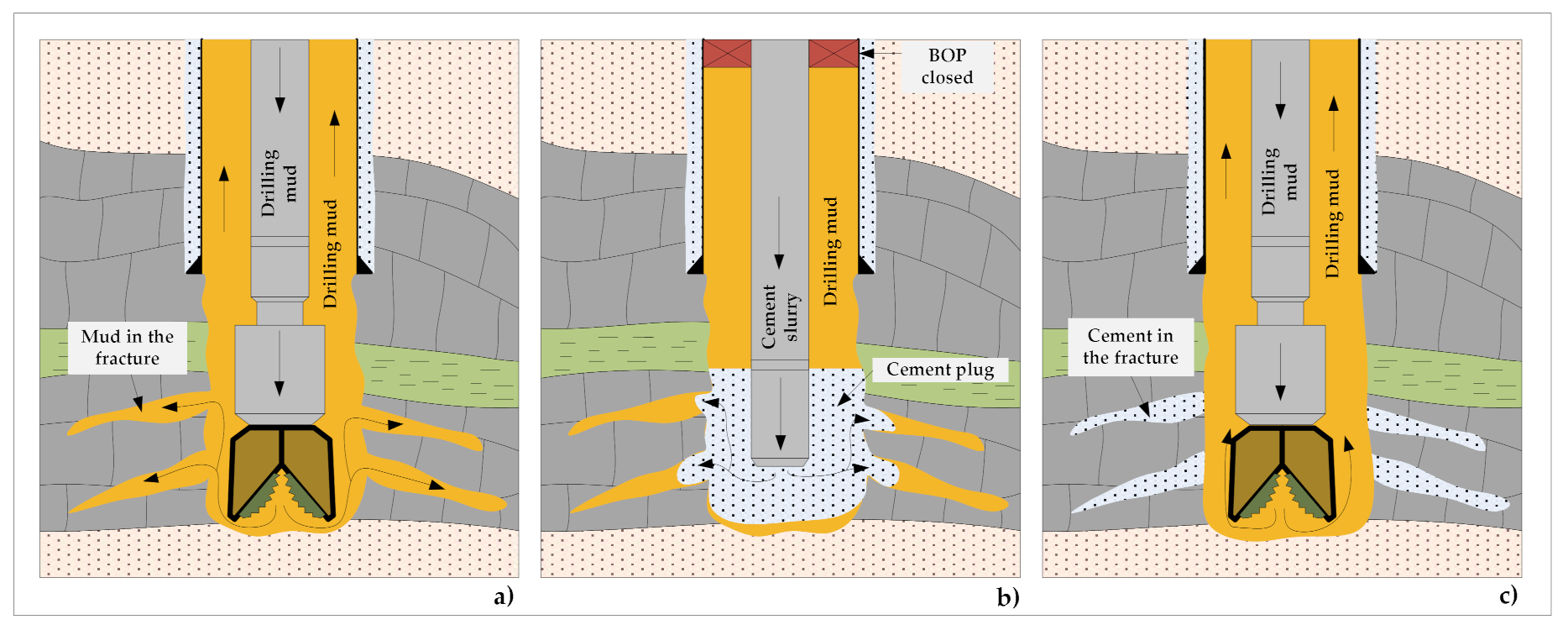
6. Procedures for Solving the Problem of Loss of Circulation during Casing Cementing

If a loss of circulation is determined, it is necessary to locate the loss zone primarily and determine the intensity of the loss of circulation. Only after the zones of loss and the intensity of the loss of circulation have been established, the selection of the cement slurry with the appropriate properties to prevent the loss of circulation is approached. In Figure 7, the sequences of procedure from the observation of losses to the solution of the lost circulation problem by selecting and designing a cement slurry of desired properties, executing cementing using an appropriate cementing method and pumping rate, and other measures to limit friction and BHP during pumping and displacing the cement slurry, are presented.

7. Discussion

The drilling of an oil and gas well, especially a deep, or extended reach horizontal well can be a technically and economically demanding process. This process is usually fraught with numerous problems as a result of an underground condition on the well site (the existence of high pressure or depleted zones, unstable zones, naturally fractured or lost circulation zones, etc.) as well as the technical limitations of the available drilling technology. These mentioned problems can be related directly to pay zones (reservoirs) or to the cap rock and overlaying formation up to the surface. Therefore, problem-solving approaches to the mentioned problems can be very different. Drilling through a naturally fractured formation is closely related to the fluid lost circulation problems during drilling or well cementing operations. Although the causes of lost circulation have been well known for decades, every new well still represents a new challenge even in a well-known areas. This problem is even more pronounced in case of a wildcat well in a relatively unexplored area due to lack of data about the presence of naturally fractured formations. Moreover, there is no specific data about fracture properties in this formation which makes the selection of prevention method very difficult. This is the reason why most of the authors represent their experiences with lost circulation problems in their manuscripts in a specific naturally fractured formation on a specific field. Unfortunately, in this way, the database is increasing but without a comprehensive, universal solution for all future cases. The lost circulation problem can be solved through preventive and different corrective actions. The emphasis should be put on preventive action and the implementation of preventive measures in the planning phase of a particular well. The planning of the lost circulation preventive action in this early stage of project development strongly depends on the available data collected on offset wells or through geological and geophysical explorations. Usually, the available data provides information about the existence of naturally fractured formations (depth and type), as well as the rate of loss, and to a lesser extent, information about the fractures themselves. The proper quantification of the existing natural fractures within a specific underground formation represents a key factor for the successful prevention of fluid loss during drilling and well cementing operations. After detailed quantification and determination of the underground fracture system and assessment of possible fluid loss, the appropriate preventive measure should be selected. Today, the drilling industry offers several high quality technical and technological solutions for lost circulation problems during drilling operations. The proper solution most often involves the correct fluid selection, the application of different wellbore strengthening or lost circulation materials, as well as the application of advanced technologies such as managed pressure drilling technology or casing drilling technology.
This indicates that the oil and gas industry struggles with the lost circulation problem on daily basis during drilling and cementing operations. Except during drilling, lost circulation can be a problem at well completion and workover operations, especially in depleted or naturally fractured reservoirs, but they are beyond the scope of this paper. Even though the causes of the problem have been identified, and high quality technical and technological solutions for the prevention of lost circulation are available, there is still room for improvement in planning strategies. The application of artificial neural networks, radial basis functions, and support vector machines is certainly welcome, but their accuracy strongly depends on a large amount of data from a specific area. Therefore, future research should be directed towards finding accurate, simple, and cheap methods for fracture system characterization and quantification before drilling. These assessment methods should be precise enough in a relatively unexplored area to prevent lost circulation problems, or at least minimize them. In this respect, it would be interesting to correlate data obtained through geophysical research (2D and 3D seismic) with available geological information, and information collected through measured/logging while drilling and afterwards through well logging. This approach will be helpful in the prevention of lost circulation, as well as in real-time adjustment of the drilling and cementing process.

8. Conclusions and Recommendations

Based on extensive research of the relevant literature dealing with lost circulation in naturally fractured formations, it is possible to conclude the following:
  • A strategy for managing lost circulation must be an integral part of well planning and should include the best drilling and cementing practice, drilling fluid and cement slurry selection, wellbore strengthening and lost circulation material selection, the appropriate corrective measures, as well as an adequate contingency plan.
  • The key to success is proper planning, risk assessment to identify potential high-risk zones, quality materials and equipment, and experienced supervision.
  • Drilling fluid and cement slurry losses into naturally fractured formations can be avoided or at least mitigated by managing the equivalent circulating density (ECD).
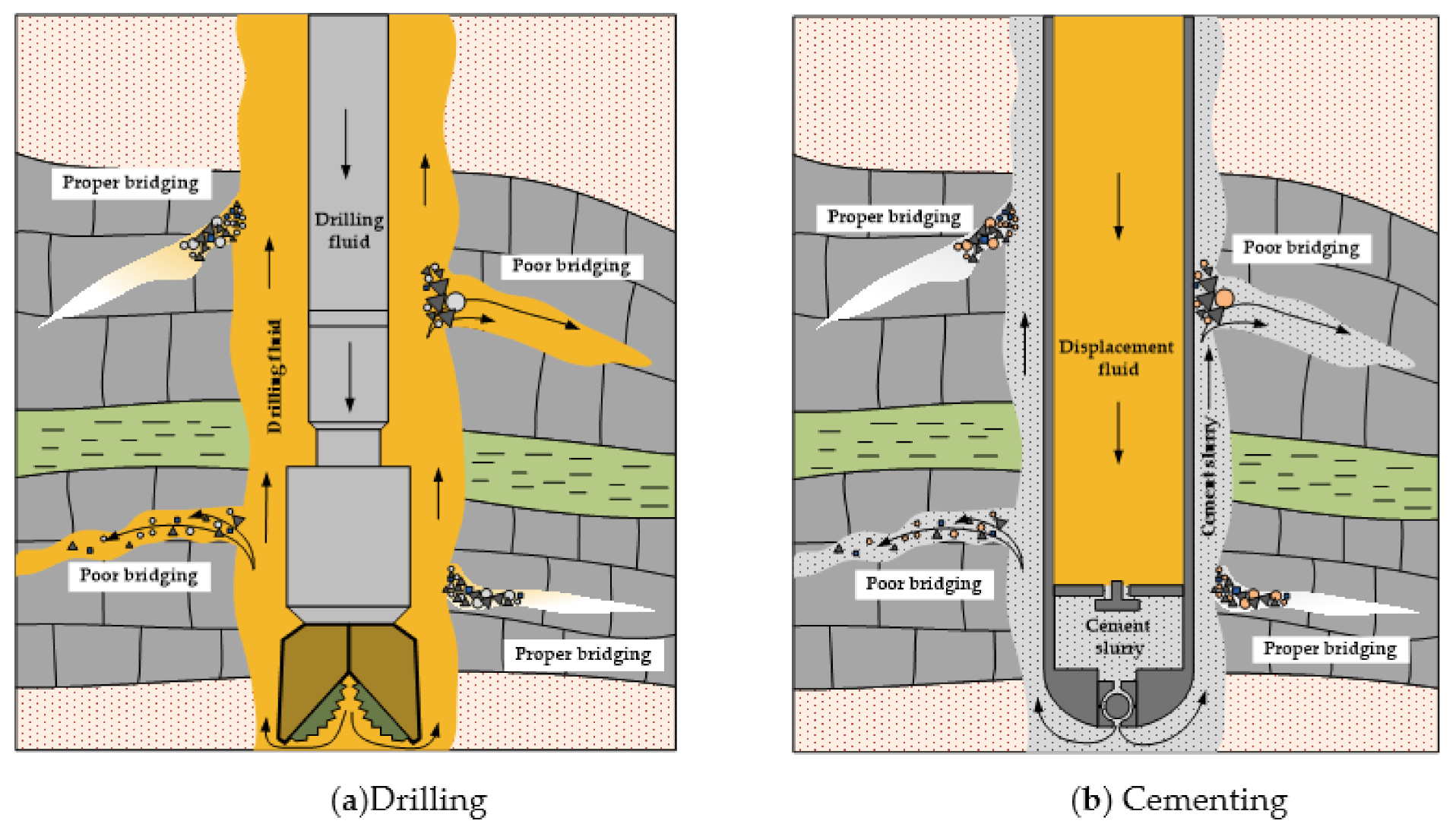
  • In the vast majority of cases, losses were initiated prior to cementing, although cementing ECDs are typically higher than drilling ECDs, which is contrary to what is often perceived, and the reason lies in the fact that a cement slurry has the inherent ability to strengthen a well.
The general recommendations for preventing or treating fluid loss in naturally fractured reservoirs are:
  • Use artificial intelligence such as artificial neural networks (ANN), radial basis function (RBF) and support vector machine (SVM) to predict the occurrence of mud loss and lost circulation zones as well as to predict the fracture width and determine the particle sizes of lost circulation materials.
  • Use available methods and tools to determine the location of the loss zone.
  • Control bottom hole pressure (BHP) in static and dynamic conditions by applying new technologies and low-density fluids.
  • Apply a wellbore strengthening strategy by adding WSMs to the mud to increase fracture pressure and avoid induced fractures or the re-opening of existing fractures.
  • Close naturally fractured formations that are also oil and gas reservoirs, select acid-soluble or time and temperature degradable conventional lost circulation materials (LCMs) and/or special LCM pills/plugs (e.g., HFHS pills, polymer-based and fiber-based pills) to avoid permanent formation damage.
  • The available materials and methods for solving the problem of lost circulation in naturally fractured reservoirs are not universal and, therefore, based on the collected well data for each specific situation, select the appropriate material and method that have proven successful in practice.

Author Contributions

N.G.-M.—Conceptualization, preparation of the comprehensive literature overview, writing, review and editing of the whole manuscript, visualization; B.P.—editing of text related to lost circulation while cementing and reviewing of the conclusion section; P.M.—writing and editing of text related to preventive measures of lost circulation and preparation of the figures; I.M.—writing and editing of text related to corrective measures of lost circulation and preparation of tables. All authors have read and agreed to the published version of the manuscript.

Funding

This research received financial support from University of Zagreb for scientific research project “Stress reduction in drill string during drilling of extended reach wells”.

Institutional Review Board Statement

Not applicable.

Informed Consent Statement

Not applicable.

Data Availability Statement

Data available in a publicly accessible repository.

Conflicts of Interest

The authors declare no conflict of interest.

References

  1. Elkatatny, S.; Gamal, H.; Ahmed, A.; Sarmah, P.; Sangaru, S.S.; Alohaly, M. A Novel Solution for Severe Loss Prevention While Drilling Deep Wells. Sustainability 2020, 12, 1339. [Google Scholar] [CrossRef] [Green Version]
  2. Caughron, D.E.; Renfrow, D.K.; Bruton, J.R.; Ivan, C.D.; Broussard, P.N.; Bratton, T.R.; Standifird, W.B. Unique Crosslinking Pill in Tandem With Fracture Prediction Model Cures Circulation Losses in Deepwater Gulf of Mexico. In Proceedings of the IADC/SPE Drilling Conference, Society of Petroleum Engineers (SPE), Dallas, TX, USA, 26–28 February 2002. [Google Scholar]
  3. Miller, M.; Scorsone, J.; Whitfill, D.L.; McDonald, M.; Miller, N. The Development of a Geopolymer-Based Pill as an Engineered Solution to Lost Circulation. In Proceedings of the SPE Annual Technical Conference and Exhibition, Society of Petroleum Engineers (SPE), New Orleans, LA, USA, 30 September–2 October 2013. [Google Scholar]
  4. Alsaba, M.; Nygaard, R.; Hareland, G.; Contreras, O. Review of Lost Circulation Materials and Treatments with an Updated Classification. In Proceedings of the AADE Fluids Technical Conference and Exhibition, Houston, TX, USA, 15–16 April 2014. [Google Scholar]
  5. Gaurina-Međimurec, N.; Pašić, B. Lost Circulation. In Risk Analysis for Prevention of Hazardous Situations in Petroleum and Natural Gas Engineering, 1st ed.; Matanović, D., Gaurina-Međimurec, N., Simon, K., Eds.; IGI Global: Hershey, PA, USA, 2014; pp. 73–95. [Google Scholar]
  6. Bychina, M.; Thomas, G.M.; Khandelwal, R.; Samuel, R. A Robust Model to Estimate the Mud Loss into Naturally Fractured Formations. In Proceedings of the SPE Annual Technical Conference and Exhibition, Society of Petroleum Engineers (SPE), San Antonio, TX, USA, 9–11 October 2017. [Google Scholar]
  7. Mahry, A.; Suryadi, D.; Sufiadi, E.; Hadinata, D.; Wahyudi, Y. Well Control in Carbonate Zone—Total Loss and Kick in Gas Reservoir. In Proceedings of the Offshore Technology Conference, Society of Petroleum Engineers (SPE), Houston, TX, 2–5 May 2016. [Google Scholar]
  8. Ramasamy, J.; Gooneratne, P.C.; Amanullah, M.D. Current Methods and Novel Solutions for Mitigating Lost Circulation. In Proceedings of the International Petroleum Technology Conference, Society of Petroleum Engineers (SPE), Beijing, China, 26–28 March 2019. [Google Scholar]
  9. Marinescu, P.; Oswald, R.J.; Vlasceanu, P. Uniquely Characteristics Mixed-Metal Oxide (MMO) Fluid Cure Lost Circulation While Meeting European Environmental Regulations. In Proceedings of the SPE Asia Pacific Oil and Gas Conference and Exhibition, Society of Petroleum Engineers (SPE), Jakarta, Indonesia, 30 October–1 November 2007. [Google Scholar]
  10. Sweatman, R.; Kessler, C.; Hillier, J. New Solutions to Remedy Lost Circulation, Crossflows, and Underground Blowouts. In Proceedings of the SPE/IADC Drilling Conference, Society of Petroleum Engineers (SPE), Amsterdam, The Netherlands, 4–6 March 1997. [Google Scholar]
  11. Ghalambor, A.; Salehi, S.; Shahri, M.P.; Karimi, M. Integrated Workflow for Lost Circulation Prediction. In Proceedings of the SPE International Symposium and Exhibition on Formation Damage Control, Society of Petroleum Engineers (SPE), Lafayette, LA, USA, 26–28 February 2014. [Google Scholar]
  12. Ruzhnikov, A. Theoretical Aspects and Practical Implementation of Study of Drilling Fluid Level in the Annulus While Drilling with Total Losses. In Proceedings of the Abu Dhabi International Petroleum Exhibition & Conference, Society of Petroleum Engineers (SPE), Abu Dhabi, UAE, 9–12 November 2020. [Google Scholar]
  13. Almetayev, R.; Al Hosani, M.; Al Ameri, S.; Al Mutawa, A.; Hussain, M.A.; Abraham, J.; Saleh, M.; Hadj-Moussa, A.; Le, K.P.D. First Nitrified Managed Pressure Drilling Application in United Arab Emirates. In Proceedings of the Abu Dhabi International Petroleum Exhibition & Conference, Society of Petroleum Engineers (SPE), Abu Dhabi, UAE, 12–15 November 2018. [Google Scholar]
  14. Aneru, S.A.; Dosunmu, A.; Anyanwu, C.; Ekeinde, E.; Odagme, B. Optimizing the Drilling HPHT/Deep Offshore Wells Using Managed Pressure Drilling Techniques. In Proceedings of the SPE Nigeria Annual International Conference and Exhibition, Society of Petroleum Engineers (SPE), Lagos, Nigeria, 5–7 August 2014. [Google Scholar]
  15. Ashraf, Q.; Khalid, A.; Luqman, K.; Hadj-Moussa, A.; Hamim, N. Underbalanced Well Intervention to Re-Enter a Dead Well Changed the Future Dynamics of the Largest Gas Field in Pakistan—A Successful Pilot Project. In Proceedings of the Abu Dhabi International Petroleum Exhibition & Conference, Society of Petroleum Engineers (SPE), Abu Dhabi, UAE, 9–12 November 2020. [Google Scholar]
  16. Gaurina-Međiumurec, N.; Simon, K.; Matanović, D.; Pašić, B. Underbalanced Drilling Technology. Min. Geol. Pet. Eng. Bull. 2006, 18, 81–95. [Google Scholar]
  17. Fattah, K.A.; El-Katatney, S.; Dahab, A. Potential implementation of underbalanced drilling technique in Egyptian oil fields. J. King Saud Univ. Eng. Sci. 2011, 23, 49–66. [Google Scholar] [CrossRef] [Green Version]
  18. Savari, S.; Butcher, J.; Al-Hulail, M. Managing Lost Circulation in Highly Fractured, Vugular Formations: Engineered Usage of High Fluid Loss Squeeze and Reticulated Foam Lost Circulation Materials. In Proceedings of the IADC/SPE International Drilling Conference and Exhibition, Society of Petroleum Engineers (SPE), Galveston, TX, USA, 3–5 March 2020. [Google Scholar]
  19. Amanullah, M.; Alouhali, R.; AlArfaj, M. A Date Tree Fiber-Based LCM for Severe Loss Control. In Proceedings of the International Petroleum Technology Conference, Society of Petroleum Engineers (SPE), Dhahran, Saudi Arabia, 13–15 January 2020. [Google Scholar]
  20. Fidan, E.; Babadagli, T.; Kuru, E. Use of Cement As Lost Circulation Material—Field Case Studies. In Proceedings of the IADC/SPE Asia Pacific Drilling Technology Conference and Exhibition, Society of Petroleum Engineers (SPE), Kuala Lumpur, Malaysia, 13–15 September 2004. [Google Scholar]
  21. Fidan, E.; Babadagli, T.; Kuru, E. Use of Cement as Lost-Circulation Material: Best Practices. In Proceedings of the Canadian International Petroleum Conference, Society of Petroleum Engineers (SPE), Calgary, AB, Canada, 8–10 June 2004. [Google Scholar]
  22. Al-Azmi, B.; Al-Mayyan, H.; Al-Saleh, F.; Godara, V.; Panchal, R.; Kosandar, B.; Tobeh, S.; Jadhav, P.; Yadav, P.; Samir, A. A Cross-Link Polymer Sealant for Curing Severe Lost Circulation Events in Fractured Limestone Formations. In Proceedings of the SPE Asia Pacific Oil & Gas Conference and Exhibition, Society of Petroleum Engineers (SPE), Adelaide, Australia, 14–16 October 2014. [Google Scholar]
  23. Alkinani, H.H.; Al-Hameedi, A.T.; Flori, R.E.; Dunn-Norman, S.; Hilgedick, S.A.; Alsaba, M.T. Updated Classification of Lost Circulation Treatments and Materials with an Integrated Analysis and their Applications. In Proceedings of the SPE Western Regional Meeting, Society of Petroleum Engineers (SPE), Garden Grove, CA, USA, 22–27 April 2018. [Google Scholar]
  24. Bruton, J.R.; Ivan, C.D.; Heinz, T.J. Lost Circulation Control: Evolving Techniques and Strategies to Reduce Downhole Mud Losses. In Proceedings of the SPE/IADC Drilling Conference, Society of Petroleum Engineers (SPE), Amsterdam, The Netherlands, 27 February–1 March 2001. [Google Scholar]
  25. Canson, B. Lost Circulation Treatments for Naturally Fractured, Vugular, or Cavernous Formations. In Proceedings of the SPE/IADC Drilling Conference, Society of Petroleum Engineers (SPE), New Orleans, LA, USA, 5–8 March 1985. [Google Scholar]
  26. Savari, S.; Rolfson, J.; Williams, R.; Whitfill, D.L.; Wang, H.M. Reticulated Foam Enhanced High Fluid Loss Squeeze LCM for Severe Lost Circulation Management in Highly Fractured Formations. In Proceedings of the SPE Deepwater Drilling and Completions Conference, Society of Petroleum Engineers (SPE), Galveston, TX, USA, 14–15 September 2016. [Google Scholar]
  27. Solomon, O.; Adewale, D.; Anyanwu, C. Fracture Width Prediction and Loss Prevention Material Sizing in Depleted Formations Using Artificial Intelligence. In Proceedings of the SPE Nigeria Annual International Conference and Exhibition, Society of Petroleum Engineers (SPE), Lagos, Nigeria, 31 July–2 August 2017. [Google Scholar]
  28. Moazzeni, A.; Nabaei, M.; Jegarluei, S.G. Prediction of Lost Circulation Using Virtual Intelligence in One of Iranian Oilfields. In Proceedings of the Nigeria Annual International Conference and Exhibition Society of Petroleum Engineers (SPE), Tinapa-Calabar, Nigeria, 31 July–7 August 2010. [Google Scholar]
  29. Abbas, A.K.; Alqatrani, G.; Mohammed, H.Q.; Dahm, H.H.; Alhumairi, M.A. Determination of Significant Parameters Affecting the Risk Level of Lost Circulation while Drilling. In Proceedings of the 54th US Rock Mechanics/Geomechanics Symposium, Golden, CO, USA, 28 June–1 July 2020. [Google Scholar]
  30. Abbas, A.K.; Al-Haideri, N.A.; Bashikh, A.A. Implementing artificial neural networks and support vector machines to predict lost circulation. Egypt. J. Pet. 2019, 28, 339–347. [Google Scholar] [CrossRef]
  31. Far, P.B.; Hosseini, P. Estimation of lost circulation amount occurs during under balanced drilling using drilling data and neural network. Egypt. J. Pet. 2017, 26, 627–634. [Google Scholar] [CrossRef] [Green Version]
  32. Toreifi, H.; Rostami, H.; Manshad, A.K. New method for prediction and solving the problem of drilling fluid loss using modular neural network and particle swarm optimization algorithm. J. Pet. Explor. Prod. Technol. 2014, 4, 371–379. [Google Scholar] [CrossRef] [Green Version]
  33. Cheraghian, G.; Wu, Q.; Mostofi, M.; Li, M.C.; Afrand, M.; Sangwai, J.S. Effect of a novel clay/silica nanocomposite on water-based drilling fluids: Improvements in rheological and filtration properties. Colloids Surf. A Physicochem. Eng. Asp. 2018, 555, 339–350. [Google Scholar] [CrossRef]
  34. Cheraghian, G.; Hemmati, M.; Bazgir, S. Application of TiO2 and fumed silica nanoparticles and improve the performance of drilling fluids. AIP Conf. Proc. 2014, 1590, 266–270. [Google Scholar] [CrossRef]
  35. Cheraghian, G. Application of Nano-Particles of Clay to Improve Drilling Fluid. Int. J. Nanosci. Nanotechnol. 2017, 13, 177–186. [Google Scholar]
  36. MI-Swaco. Prevention and Control of Lost Circulation. 2011. Available online: https://www.academia.edu/17116360/Manual_prevention_an_control_of_lost_circulation (accessed on 5 December 2020).
  37. Chen, Y.; Yu, M.; Ozbayoglu, M.E.; Takach, N. Numerical Model for Mapping Thief Zones in Directional Wells while Drilling. In Proceedings of the SPE Annual Technical Conference and Exhibition, Society of Petroleum Engineers (SPE), Amsterdam, The Netherlands, 27–29 October 2014. [Google Scholar]
  38. Wang, H.; Sweatman, R.E.; Engelman, R.E.; Deeg, W.F.; Whitfill, D.L. The Key to Successfully Applying Today’s Lost Circulation Solutions. In Proceedings of the SPE Annual Technical Conference and Exhibition, Society of Petroleum Engineers (SPE), Dallas, TX, USA, 9–12 October 2005. [Google Scholar]
  39. Akamine, A.Y.; Bratton, T.; Onyia, E.; Romanchock, M. Application of Real-Time Resistivity and Annular Pressure Data in Reducing Lost-Circulation Events. In Proceedings of the SPE/IADC Drilling Conference, Society of Petroleum Engineers (SPE), Amsterdam, The Netherlands, 19–21 February 2003. [Google Scholar]
  40. Bratton, T.; Rezmer-Cooper, I.; Desroches, J.; Gille, Y.E.; Li, Q.; Mcfayden, M. How to Diagnose Drilling Induced Fractures in Wells Drilled with Oil-Based Muds with Real-Time Resistivity and Pressure Measurements. In Proceedings of the SPE/IADC Drilling Conference, Society of Petroleum Engineers (SPE), Amsterdam, The Netherlands, 27 February–1 March 2001. [Google Scholar]
  41. Chilingarian, G.V.; Vorabutr, P. Lost Circulation. In Drilling and Drilling Fluids; Elsvier: Amsterdam, The Netherlands, 1981; pp. 537–557. [Google Scholar]
  42. Ahmed, A.; Elkatatny, S.; Abdulraheem, A.; Abughaban, M. Prediction of Lost Circulation Zones using Support Vector Machine and Radial Basis Function. In Proceedings of the International Petroleum Technology Conference, Society of Petroleum Engineers (SPE), Dhahran, Saudi Arabia, 13–15 January 2020. [Google Scholar]
  43. Nayberg, T. Laboratory Study of Lost Circulation Materials for Use in Both Oil-Based and Water-Based Drilling Muds. SPE Drill. Eng. 1987, 2, 229–236. [Google Scholar] [CrossRef]
  44. Nelson, E.B.; Guillot, D. Well Cementing, 2nd ed.; Schlumberger: Houston, TX, USA, 2006. [Google Scholar]
  45. Hitchcock, G. Additive Manufactured Shapes used to Cure Total Lost Circulation Events. In Proceedings of the Offshore Technology Conference, Society of Petroleum Engineers (SPE), Houston, TX, USA, 4–7 May 2020. [Google Scholar]
  46. Drilling Specialities Company Adevision of Chevron Phillips Chemical Company LP. Lost Circulation Guide. 2014. Available online: https://www.cpchem.com/sites/default/files/2020-04/LOSS%20OF%20CIRCULATION%20Guide.pdf (accessed on 8 January 2014).
  47. Olsen, M.; Lende, G.; Rehman, K.; Haugum, P.; Mo, J.; Smaaskjar, G.; Næss, R. Innovative and Established LCM Cementing Solutions Combined to Create Novel LCM Cementing Fluid Train. In Proceedings of the SPE Norway One Day Seminar, Society of Petroleum Engineers (SPE), Bergen, Norway, 14 May 2019. [Google Scholar]
  48. Therond, E.; Taoutaou, S.; James, S.G.; Way, P.W.; Gomes, P.; Dondale, A. Understanding Lost Circulation While Cementing: Field Study and Laboratory Research. SPE Drill. Complet. 2018, 33, 77–86. [Google Scholar] [CrossRef]
  49. Abbas, R.; Jarouj, H.; Dole, S.; Junaidi, E.H.; El-Hassan, H.; Francis, L.; Hornsby, L.; McCraith, S.; Shuttleworth, N.; van der Plas, K.; et al. A Safety Net for Controlling Lost Circulation. Oilfield Rev. Winter 2003, 15, 20–27. [Google Scholar]
  50. Al-Hameedi, A.T.T.; Alkinani, H.H.; Dunn-Norman, S.; Flori, R.E.; Hilgedick, S.A.; Amer, A.S.; Alsaba, M. Mud loss estimation using machine learning approach. J. Pet. Explor. Prod. Technol. 2018, 9, 1339–1354. [Google Scholar] [CrossRef] [Green Version]
  51. Efendiyev, G.; Mammadov, P.; Piriverdiyev, I.; Mammadov, V. Clustering of Geological Objects Using FCM-algorithm and Evaluation of the Rate of Lost Circulation. Procedia Comput. Sci. 2016, 102, 159–162. [Google Scholar] [CrossRef]
  52. Alkinani, H.H.; Al-Hameedi, A.T.T.; Dunn-Norman, S.; Alkhamis, M.M.; Mutar, R.A. Prediction of Lost Circulation Prior to Drilling for Induced Fractures Formations Using Artificial Neural Networks. In Proceedings of the SPE Oklahoma City Oil and Gas Symposium, Society of Petroleum Engineers (SPE), Oklahoma City, OK, USA, 9–10 April 2019. [Google Scholar]
  53. Whitfill, D.L. Lost Circulation Material Selection, Particle Size Distribution and Fracture Modeling with Fracture Simulation Software. In Proceedings of the IADC/SPE Asia Pacific Drilling Technology Conference, Society of Petroleum Engineers (SPE), Jakarta, Indonesia, 25–27 August 2008. [Google Scholar]
  54. Kumar, A.; Savari, S. Lost Circulation Control and Wellbore Strengthening: Looking Beyond Particle Size Distribution. In Proceedings of the AADE National Technical Conference and Exhibition, Houston, TX, USA, 12–14 April 2011. [Google Scholar]
  55. Gaurina-Međimurec, N.; Pašić, B.; Mijić, P. Risk Planning and Mitigation in Oil Well Fields. Int. J. Risk Conting. Manag. 2015, 4, 27–48. [Google Scholar] [CrossRef]
  56. Aston, M.; Alberty, M.; McLean, M.; De Jong, H.; Armagost, K. Drilling Fluids for Wellbore Strengthening. In Proceedings of the IADC/SPE Drilling Conference, Society of Petroleum Engineers (SPE), Dallas, TX, USA, 2–4 March 2004. [Google Scholar]
  57. Wang, H.; Sweatman, R.E.; Engelman, R.; Deeg, W.F.; Whitfill, D.L.; Soliman, M.Y.; Towler, B.F. Best Practice in Understanding and Managing Lost Circulation Challenges. SPE Drill. Complet. 2008, 23, 168–175. [Google Scholar] [CrossRef]
  58. Fan, X.; Zhang, Q.; Wang, J.; Xu, L.; Zhang, P.; Jia, W.; Chen, X.; Yu, G.; Yang, Y. Mathematical methods for evaluating a reservoir based on gas dynamic monitoring during underbalanced drilling. J. Nat. Gas Sci. Eng. 2015, 26, 1068–1079. [Google Scholar] [CrossRef]
  59. Wu, H.; Chen, P.; Fan, X.; Xia, H.; Wang, J.; Wang, J.; Wu, J. Research on Rapid Identification and Evaluation Technology for Gas Formation during Underbalanced Drilling. Geofluids 2017, 2017, 1–8. [Google Scholar] [CrossRef] [Green Version]
  60. Pedersen, T.; Godhavn, J.-M.; Schubert, J. Supervisory control for underbalanced drilling operations. IFAC PapersOnLine 2015, 48, 120–127. [Google Scholar] [CrossRef]
  61. Ladmia, A.; Culen, M.; Al Katheeri, A.B.; Al Hosani, F.M.A.; Edmonstone, G.F.J.; Mantilla, A.; Baslaib, M.A.; Nabil, I.M.; Yousfi, F.Z.; Al Hosani, M.A.; et al. Underbalance Coiled Tubing Drilling in Tight Gas Reservoir Study Case Onshore Field, Abu Dhabi. In Proceedings of the Abu Dhabi International Petroleum Exhibition & Conference, Society of Petroleum Engineers (SPE), Abu Dhabi, UAE, 9–12 November 2020. [Google Scholar]
  62. Salehi, S.; Hareland, G.; Nygaard, R. Numerical simulations of wellbore stability in under-balanced-drilling wells. J. Pet. Sci. Eng. 2010, 72, 229–235. [Google Scholar] [CrossRef]
  63. Fossli, B.; Sangesland, S. Controlled Mud-Cap Drilling for Subsea Applications: Well-Control Challenges in Deep Waters. SPE Drill. Complet. 2006, 21, 133–140. [Google Scholar] [CrossRef]
  64. Emam, S.S.; Brand, P.R.; Gabaldon, O.R.; Vityk, M.; El Leithy, A.; Shanab, M.A.; Hamdy, B.; Abdel-Moniem, M.; El-Desouky, W.; El-Azm, H.A. Use of Managed Pressure Drilling Paved the Way to a Massive Gas Field Discovery in Egypt Western Desert: Case History. In Proceedings of the SPE/IADC Middle East Drilling Technology Conference and Exhibition, Society of Petroleum Engineers (SPE), Abu Dhabi, UAE, 29–31 January 2018. [Google Scholar]
  65. Gedge, B.J.; Tan, C.Y.; Rao, J.; Singh, H.K.D.; Oracion, J.; Quoc, B.T.; Nguyen, V.B.; Tran, N.H.; Minh, T.L.T.; Buitenhuis, R.J.; et al. The Deployment of Managed Pressure Drilling Technology, to Assist in the Development of Offshore HPHT Gas Condensate Fields in Vietnam—Planning, Engineering, and Implementation. In Proceedings of the SPE Asia Pacific Oil & Gas Conference and Exhibition, Society of Petroleum Engineers (SPE), Adelaide, Australia, 14–16 October 2014. [Google Scholar]
  66. Goodwin, B.; Nauduri, S.; Medley, G. MudCap Drilling: New Variations, Drivers, Limitations, and Lessons Learned–Case Histories. In Proceedings of the SPE/IADC Managed Pressure Drilling & Underbalanced Operations Conference & Exhibition, Society of Petroleum Engineers (SPE), Madrid, Spain, 8–9 April 2014. [Google Scholar]
  67. Kurbanov, V.; Rotaru, A.; Gribanov, V.; Bakhitov, R.; Sidorov, Y. Managed Pressure Drilling Overcomes Drilling Challenges and Enhances Oil Production of Naturally Fractured Carbonate Reservoir of East Siberia. In Proceedings of the SPE Russian Petroleum Technology Conference, Society of Petroleum Engineers (SPE), Moscow, Russia, 22–24 October 2019. [Google Scholar]
  68. Grijalva, O.; Holzmann, J.; Oppelt, J.; Perozo, N.; Paz, C.; Asgharzadeh, A. OCTG Advancements in Casing Drilling: Where We Have Been and Where Are We Going? In Proceedings of the SPE Oklahoma City Oil and Gas Symposium, Oklahoma City, OK, USA, 27–31 March 2017. [Google Scholar] [CrossRef]
  69. Gaurina-Međimurec, N. Casing Drilling Technology. Min. Geol. Pet. Eng. Bull. 2005, 17, 19–26. [Google Scholar]
  70. Ofei, T.N.; Jalaludin, A.N.; Habte, A.D.; Lemma, T.A.; Ben-Awuah, J. Investigation of Plastering Effect in Casing-while-Drilling—A CFD Study. IOP Conf. Ser. Mater. Sci. Eng. 2019, 495, 012071. [Google Scholar] [CrossRef] [Green Version]
  71. Kiran, R.; Karimi, M.; Salehi, S. Finite Element Analysis of Casing Drilling Smearing Effect. In Proceedings of the SPE Deepwater Drilling and Completions Conference, Society of Petroleum Engineers (SPE), Galveston, TX, USA, 10–11 September 2014. [Google Scholar]
  72. Naveen, V.; Babu, V. Experimental Study of Plastering Effect During Casing While Drilling. In Proceedings of the Abu Dhabi International Petroleum Exhibition & Conference, Society of Petroleum Engineers (SPE), Abu Dhabi, UAE, 10–13 November 2014. [Google Scholar]
  73. Chima, J.; Zhou, S.; Al-Hajji, A.; Okot, M.; Sharif, Q.J.; Clark, D.; Oveson, D.; Moellendick, E.; Holt, C.; Neidhardt, D. Casing Drilling Technology Application: Case Histories from Saudi Arabia. In Proceedings of the SPE Saudi Arabia Section Technical Symposium and Exhibition, Al-Khobar, Saudi Arabia, 8–11 April 2012. [Google Scholar] [CrossRef]
  74. Karimi, M.; Ghalambor, A.; Montgomery, M.; Moellendick, T.E. Formation Damage and Fluid Loss Reduction due to Plastering Effect of Casing Drilling. In Proceedings of the SPE European Formation Damage Conference, Society of Petroleum Engineers (SPE), Noordwijk, The Netherlands, 7–10 June 2011. [Google Scholar]
  75. Meza, O.G.; Yaqoob, T.; Bello, O.; Boulakhrif, F.; Holzmann, J.; Oppelt, J. Combined Investigation of Effects of Contact Stresses, Pore Size and Rotary Dynamics on Mud Plastering in Prevention of Lost Circulation in Weak Zones during Casing Drilling. In Proceedings of the Abu Dhabi International Petroleum Exhibition & Conference, Society of Petroleum Engineers (SPE), Abu Dhabi, UAE, 13–16 November 2017. [Google Scholar]
  76. Ezeakacha, C.; Salehi, S.; Ghalambor, A.; Karimi, M. An Integrated Study of Mud Plastering Effects for Reducing Filtrate’s Invasion. In Proceedings of the SPE International Conference and Exhibition on Formation Damage Control, Society of Petroleum Engineers (SPE), Lafayette, LA, USA, 24–26 February 2016. [Google Scholar]
  77. Grant, T.; Bullock, M. The Evolution Of Solid Expandable Tubular Technology: Lessons Learned Over Five Years. In Proceedings of the Offshore Technology Conference, Society of Petroleum Engineers (SPE), Huston, TX, USA, 2–5 May 2005. [Google Scholar]
  78. Gusevik, R.; Cooper, B.; Cameron, J.R. Expandable Solid-Steel Liner Applications in the Marcellus. In Proceedings of the SPE Eastern Regional Meeting, Pittsburgh, PA, USA, 20–22 August 2013. [Google Scholar] [CrossRef]
  79. Park, M.; Teasdale, P.; Cowling, M. Application of Uncemented Solid Expandable Liner for Combined Openhole Isolation and Casing Repair. In Proceedings of the SPE/IADC Drilling Conference and Exhibition, Society of Petroleum Engineers (SPE), London, UK, 17–19 March 2015. [Google Scholar]
  80. Rahman, R.A.; Zulkafly, A.H. Issues and Solutions for Cementing Expandable Liners: A Case History. In Proceedings of the IADC/SPE Drilling Conference, Society of Petroleum Engineers (SPE), Dallas, TX, USA, 2–4 March 2004. [Google Scholar]
  81. Stringer, J.A.; Farley, D.B. The Evolution of Expandables: A New Era of. In Proceedings of the SPE Middle East Oil & Gas Show and Conference, Society of Petroleum Engineers (SPE), Manama, Baherin, 10–13 March 2013. [Google Scholar]
  82. Luzardo, J.; Oliveira, E.P.; Derks, P.W.J.; Nascimento, R.V.; Pérez-Gramatges, A.; Valle, R.; Pantano, I.G.; Sbaglia, F.; Inderberg, K. Alternative Lost Circulation Material for Depleted Reservoirs. OTC Brasil 2015. [Google Scholar] [CrossRef]
  83. Droger, N.; Eliseeva, K.; Todd, L.; Ellis, C.; Salih, O.; Silko, N.; Fu, D.; Meyer, A.; Bermudez, R. Degradable Fiber Pill for Lost Circulation in Fractured Reservoir Sections. In Proceedings of the IADC/SPE Drilling Conference, Society of Petroleum Engineers (SPE), Fort Worth, TX, USA, 4–6 March 2014. [Google Scholar]
  84. Fomenkov, A.; Pinigin, I.; Mikliayev, M.; Fedyanin, A. Using Thixotropic Cement Slurry for Lost Circulation Control: Case History, Volga-Urals Region. In Proceedings of the SPE Russian Petroleum Technology Conference, Society of Petroleum Engineers (SPE), Moscow, Russia, 22–24 October 2019. [Google Scholar]
  85. Whitfill, D.L.; Hemphill, T. All Lost-Circulation Materials and Systems Are Not Created Equal. In Proceedings of the SPE Annual Technical Conference and Exhibition, Society of Petroleum Engineers (SPE), Denver, CO, USA, 5–18 October 2003. [Google Scholar]
  86. Available online: https://www.slb.com/drilling/drilling-fluids-and-well-cementing/drilling-fluids/drilling-fluid-additives/wellbore-strengthening-materials/optiseal-wellbore-strengthening-material-blend (accessed on 5 December 2020).
  87. Jeennakorn, M.; Alsaba, M.; Nygaard, R.; Saasen, A.; Nes, O.M. The effect of testing conditions on the performance of lost circulation materials: Understandable sealing mechanism. J. Pet. Explor. Prod. Technol. 2018, 9, 823–836. [Google Scholar] [CrossRef] [Green Version]
  88. Zhong, H.; Shen, G.; Yang, P.; Qiu, Z.; Jin, J.; Xing, X. Mitigation of Lost Circulation in Oil-Based Drilling Fluids Using Oil Absorbent Polymers. Materials 2018, 11, 2020. [Google Scholar] [CrossRef] [Green Version]
  89. Kulkarni, S.D.; Savari, S.; Gupta, N.; Whitfill, D. Designing Lost Circulation Material LCM Pills for High Temperature Applications. In Proceedings of the SPE Deepwater Drilling and Completions Conference, Society of Petroleum Engineers (SPE), Galveston, TX, USA, 14–15 September 2016. [Google Scholar]
  90. Amanullah, M.D. Characteristics, Behavior and Performance of ARC Plug—A Date Seed-Based Sized Particulate LCM. In Proceedings of the SPE Kingdom of Saudi Arabia Annual Technical Symposium and Exhibition, Dammam, Saudi Arabia, 25–28 April 2016. [Google Scholar] [CrossRef]
  91. Murray, D.; Sanders, M.W.; Houston, K.; Hogg, H.; Wylie, G. Case Study—ECD Management Strategy Solves Lost Circulation Issues On Complex Salt Diapirs/Paleocene Reservoir. In Proceedings of the SPE Annual Technical Conference and Exhibition, Society of Petroleum Engineers (SPE), New Orleans, LA, USA, 30 September–2 October 2013. [Google Scholar]
  92. Sanders, W.W.; Williamson, R.N.; Ivan, C.D.; Powell, D. Lost Circulation Assessment and Planning Program: Evolving Strategy to Control Severe Losses in Deepwater Projects. In Proceedings of the SPE/IADC Drilling Conference, Society of Petroleum Engineers (SPE), Amsterdam, The Netherlands, 19–21 February 2003. [Google Scholar]
  93. DuPriest, F.E.; Smith, M.V.; Zeilinger, S.C.; Shoykhet, N. Method To Eliminate Lost Returns and Build Integrity Continuously With High-Filtration-Rate Fluid. In Proceedings of the IADC/SPE Drilling Conference, Society of Petroleum Engineers (SPE), Orlando, FL, USA, 4–6 March 2008. [Google Scholar]
  94. Oliveira, J.A.A.; Zago, J.; Fontes, C.; Waldmann, A.T.A.; Martins, A.L. Modeling Drilling Fluid Losses in Fractured Reservoirs. In Proceedings of the SPE Latin America Petroleum Engineering Conference, Society of Petroleum Engineers (SPE), Mexico City, Mexico, 16–18 April 2012. [Google Scholar]
  95. Savari, S.; Whitfill, D.L. Managing Losses in Naturally Fractured Formations: Sometimes Nano is too Small. In Proceedings of the SPE/IADC Drilling Conference and Exhibition, Society of Petroleum Engineers (SPE), London, UK, 17–19 March 2015. [Google Scholar]
  96. Savari, S.; Whitfill, D.L.; Walker, J. Lost Circulation Management in Naturally Fractured Reservoirs. In Proceedings of the SPE/IADC Middle East Drilling Technology Conference and Exhibition, Society of Petroleum Engineers (SPE), Abu Dhabi, UAE, 26–28 January 2016. [Google Scholar]
  97. Ivan, C.; Bruton, J.; Bloys, B. How can we best manage lost circulation? In Proceedings of the AADE National Technology Conference “Practical Solutions for Drilling Challenges”, Houston, TX, USA, 1–3 April 2003. [Google Scholar]
  98. Mofunlewi, S.S.; Okoto, F. Curing Lost Circulation with an Engineered Spacer During Cement Placement. In Proceedings of the SPE Nigeria Annual International Conference and Exhibition, Society of Petroleum Engineers (SPE), Lagos, Nigeria, 2–4 August 2016. [Google Scholar]
  99. Apourvari, S.N.; Schaffie, M.; Farazmand, R. A new formulation for lightweight oil well cement slurry using a natural pozzolan. Adv. Geo. Energy Res. 2019, 3, 242–249. [Google Scholar] [CrossRef]
  100. Veisi, M.S.; Taoutaou, S.; Steven, A.; Pasteris, M.; Wedhaswari, V.R.; Awalt, M.; Kadrie, M.; Permata, E. Engineered Highly Crush-Resistant Cement Slurry to Prevent Lost Circulation. In Proceedings of the SPE/IATMI Asia Pacific Oil & Gas Conference and Exhibition, Society of Petroleum Engineers (SPE), Nusa Dua, Bali, Indonesia, 20–22 October 2015. [Google Scholar]
  101. Mata, F.; Veiga, M. Crosslinked Cements Solve Lost Circulation Problems. In Proceedings of the SPE Annual Technical Conference and Exhibition, Society of Petroleum Engineers (SPE), Houston, TX, USA, 26–29 September 2004. [Google Scholar]
  102. Yuan, B.; Yang, Y.; Tang, X.; Xie, Y. A starting pressure prediction of thixotropic cement slurry: Theory, model and example. J. Pet. Sci. Eng. 2015, 133, 108–113. [Google Scholar] [CrossRef]
  103. Effendhy, J.H.; Abbas, R.; Malik, B. Fibers in Cement Form Network to Cure Lost Circulation. World Oil Mag. 2003, 48–50. [Google Scholar]
  104. Putra, T.; Steven, A.; Wedhaswari, V.R.; Awalt, M.S.; Natanagara, B.B.; Pasteris, M.; Jaffery, M.F.; Veisi, M.S.; Rudiantoro, A. Novel Cementing Solutions to Impede Lost Circulation with Highly Crush-Resistant Lightweight Cement System and Engineered Fibers. In Proceedings of the SPE Asia Pacific Oil & Gas Conference and Exhibition, Society of Petroleum Engineers (SPE), Perth, Australia, 25–27 October 2016. [Google Scholar]
  105. Pavić, V.; Gaurina-Međimurec, N.; Ružić, M. Foam Cement Slurry in Petroleum Industry (In Croatian: Pjenocementne kaše u naftnoj industriji). Nafta 1989, 40, 753–761. [Google Scholar]
  106. Fomenkov, A.; Pinigin, I.; Velikiy, D.; Denisov, I. Positive Experience Using Foam Cementing Technology for Production Casing Cementing in the Volga-Ural Field. In Proceedings of the SPE Russian Petroleum Technology Conference, Society of Petroleum Engineers (SPE), Moscow, Russia, 26–29 October 2020. [Google Scholar]
  107. Fomenkov, A.; Pinigin, I.; Zyryanov, V.; Fedyanin, A. Foam Cementing in the Volga-Ural Region: Case Study. In Proceedings of the SPE Russian Petroleum Technology Conference, Society of Petroleum Engineers (SPE), Moscow, Russia, 15–17 October 2018. [Google Scholar]
  108. Nayberg, T.; Petty, B. Laboratory Study of Lost Circulation Materials for Use in Oil-Base Drilling Muds. In Proceedings of the SPE Deep Drilling and Production Symposium, Amarillo, TX, USA, 6–8 April 1986. [Google Scholar] [CrossRef]
  109. El-Hassan, H.I.; Abbas, R.; Jarouj, H.; Munk, T. Using a Novel Fiber Cement System to Control Lost Circulation: Case Histories from the Middle East and the Far East. In Proceedings of the SPE/IADC Middle East Drilling Technology Conference and Exhibition, Society of Petroleum Engineers (SPE), Abu Dhabi, UAE, 20–22 October 2003. [Google Scholar]
  110. Low, N.; Daccord, G.; Bedel, J.P. Designing Fibered Cement Slurries for Lost Circulation Applications: Case Histories. In Proceedings of the SPE Annual Technical Conference and Exhibition, Society of Petroleum Engineers (SPE), Denver, CO, USA, 5–8 October 2003. [Google Scholar]
  111. Ahmed, A.; Elkatatny, S.; Gajbhiye, R.; Rahman, M.K.; Sarmah, P.; Yadav, P. Effect of Polypropylene Fibers on Oil-Well Cement Properties at HPHT Condition. In Proceedings of the SPE Kingdom of Saudi Arabia Annual Technical Symposium and Exhibition, Damman, Saudi Arabia, 23–26 April 2018. [Google Scholar]
Figure 1. Preventive and corrective measures hierarchy (a) and wellbore strengthening (b).
Applsci 11 00767 g001
Figure 2. Fluid systems used in underbalanced drilling comparing to conventional drilling.
Applsci 11 00767 g002
Figure 3. Comparison of pressure gradients and safe drilling window.
Applsci 11 00767 g003
Figure 4. Illustration of lost circulation during drilling (a) and cementing (b).
Applsci 11 00767 g004
Figure 5. Plugging the thief zone with the thixotropic cement slurry: (a) loss of mud during drilling, (b) pumping and spotting of a thixotropic cement slurry into thief zone, (c) the situation in the well after hardening of the cement slurry into set cement of sufficient strength to withstand various stresses in the future.
Applsci 11 00767 g005
Figure 6. Procedure of spotting and squeezing cement-based plugs or polymer-based pills.
Applsci 11 00767 g006
Figure 7. Sequence of procedures for solving the problem of loss of circulation during casing cementing.
Applsci 11 00767 g007
Table 1. The probable location of the thief zone according to [36].
Thief zone is “on bottom” if:Thief zone is “off bottom” if:
Fluid loss first occurs while drilling ahead.
Fluid loss is accompanied by a notable change in the rate of penetration (ROP), torque, or drilling vibration.
Fluid loss is due to natural fractures, faults, caverns, vugs or high permeability sands and gravels (well site geology data, drilling break with increase in torque and kelly free falls while drilling coupled with an instant loss in circulation).
Fluid loss first occurs while tripping, drilling fast or increasing mud weight.
Fluid loss is the result of shutting the well in and killing the well.
A annular loading is such as to increase the return apparent mud weight higher than the last casing shoe fracture gradient.
Table 2. Classification of mud loss according to its severity [5].
Severity of LossRate of LossType of Formation
Seepage0.16 to 1.6 m3/hAny permeable formation type when the bridging agents are not large enough to form a seal, or when there are no fine particles to complete the seal.
Partial1.6 m3/h to 16 m3/hHighly porous or fractured formations, gravel, small natural fractures and barely opened induced fractures.
Completemud level at 61 to 152 m below wellheadLong, open sections of gravel, long intervals of small natural fractures, large natural fractures (caverns, vugs) or open induced fractures.
Severe completemud level at 152 to 305+ m below wellheadLarge, open natural fractures, caverns, and open induced fractures.
Table 3. Classification of losses according to different authors and companies.
SourceSeverity of Loss
Seepage
(Minor)
Partial
(Moderate/Medium)
Severe
(Massive/Complete)
Total
(Complete)
Typical Loss Rate (m3/h)
Hitchock, 2020 [45]; Drilling Specialties Company, 2014 [46]Water-based mud
<44 to 16>16no returns
Oil-based mud
<1.61.6 to 4.8>4.8no returns
Ramasamy et al., 2019 [8]<1.61.6 to 3.23.2 to 32no returns
Olsen et al., 2019 [47]-->25no returns
Therond et al., 2018 [48]<1.61.6 to 1616 to 80no returns
MI-Swaco, 2011 [36]<1.61.6 to 16-no returns
Mahry et al., 2016 [7]-1.6 to 8-no returns
Ghalambor et al., 2014 [11]; Marinescu et al., 2007 [9]-1.6 to 8 (s.c.)
10 to 20% of the mud (d.c.)
8 to 24 (s.c.)
50 to 100% of the mud (d.c.)
no returns
Nayberg, 1987 [43]; Nelson, 2006 [44]; Alsaba et al., 2014 [4]0.16 to 1.61.6 to 80>80no returns
Jarouj et al., 2003/2004 [49]<1.6>1.6, but some fluid returns-no returns
Sweatman et al., 1997 [10]1.6 to 3.2 (s. c.); 0.16 to 1.6 (d. c.)-8 to 24 (s. c.); 50 to 100% of the mud (d. c.)no returns
Al-Hameedi et al., 2018 [50]<11 to 10>15no returns
Note: s.c.—static condition; d.c.—dynamic conditions.
Table 4. Preventive measures to avoid lost circulation during drilling.
Preventive Measures
1.   Controlling bottom hole pressure (BHP)
Minimizing the hydrostatic pressure in the wellbore using drilling fluid which has the minimum safe density.
Maintaining proper mud weight.
Minimizing annular-friction pressure losses during drilling and tripping in.
Minimizing the equivalent circulating density (ECD) by changing the mud properties (plastic viscosity, yield point, and gel strengths) within the safe margin.
Adequate hole cleaning.
Avoiding restrictions in the annulus.
Updating information about formation pore pressure and fracture gradients for better accuracy with log and drilling data.
Applying appropriate drilling technology: underbalanced drilling (UBD), managed pressure drilling (MPD), casing while drilling (CwD).
2.   Wellbore pressure containment improvement (WPCI)
(WPCI treatment with a required amount of sealant volume is used to increase the pressure-containment integrity of the entire open hole and to allow an increase in the mud weight without loss in the continuation of drilling to the total depth.)
3.   Running intermediate casing in the transition zones
(Setting casing to protect upper weaker formations within a transition zone.)
4.   Setting Solid Expandable Tubulars (SET)
(Installation of clad liner with external seals and other external attachment for covering the lost circulation and depleted zone in open hole section.)
5.   Wellbore strengthening
(Increasing the fracture resistance by increasing the hoop stress in the near wellbore region.)
Table 5. Lost circulation materials (LCMs).
Lost Circulation Materials (LCMs)
Conventional LCMSpecially Designed LCM
Flaky LCMflaked calcium carbonate, mica, cellophane, vermiculite, and corncobsCement Plug
Ultra-thixotropic and thixotropic cement slurries including calcium carbonate, flakes, and mica for mechanical bridging.
Granular LCMcalcium carbonate, nutshells, gilsonite, graphite, asphalt, perlite, and course bentonitePolyurethane Grouting
Mixtures or solutions that react to produce a gel or foam.(Single component prepolymerized polyurethanes that require water to react and two component polyurethanes that are mixed and react with each other).
Fibrous LCMsawdust, cellulose fibers, shredded paper, mineral fibers, and nylon fibersGeopolymer-Based Pill
Chemically reactive pill based on aqueous alkali alumino silicates.
Blended LCMa mixture of two or more types of LCMSettable Plug
A plug is utilized for slurry, which is a gel or solidified; keeps fluid at low viscosity and reacts at certain bottom hole temperature.
Water-/Acid-Soluble LCMcalcium carbonate, fiber, ground marble and saltsCross-linked Gel
A high-viscosity gel formed by the development of cross-linked bonds between polymer chains making the polymer network.
Hydratable/Swellable LCMA mixture of different LCM with a highly reactive polymerViscoelastic Surfactant
It is made of surfactants that self-assemble into worm-like micellar structures that act as polymers, raising the viscosity of the mud at low shear rates.
Nanoparticles LCMiron hydroxide, calcium carbonate, and silica nanoparticlesDegradable Fiber Pill
A fiber pill maintains stability for required time, but eventually self-degrade within desired time frame over a broad Bottomhole Temperature (BHT) range.
Table 6. Cement slurry additives—extenders and lost circulation control agent [modified to 44].
CategoryCompositionMechanism of Reaction
Extender
(Benefit: lower slurry density; higher slurry yield)
BentoniteAbsorption of water
Sodium silicatesFormation of C-S-H gel and absorption of water
Pozzolans (Diatomaceous earth, Fly ash, Fume silica)Lower density than cement
Gilsonite
Powdered coal
Microspheres
NitrogenFoamed cement
Lost-circulation control agent
(Benefit: prevent loss of slurry to formation)
GilsoniteBridging effect across formation
Granular coal
Cellophane flake
Nut Shells
Fibrous Additives
GypsumInduce thixotropic behavior of cement slurry
Soluble sulfate salts
Bentonite
Crosslinked cellulosic polymers
Table 7. Some common cement extenders and minimum achievable slurry density range.
ExtenderMinimum Achievable Density of Cement Slurry (kg/m3)Common Concentration
Active Extenders
Bentonite1380Up to 20% BWOC
Diatomaceous Earth1320Up to 40% BWOC
Silica1200Up to 28% BWOC
Fly Ashes1572Fly Ash/Cement ratio is 1:3 to 3:1
(+2% bentonite)
Sodium Silicates1332Solid sodium silicate (Sodium metasilicate): 0.2% to 3.0% BWOC
Liquid sodium silicate (water glass): 0.8 to 2.3 l/sk
Inert Extenders
Expanded perlite
(Volcanic Glass)
1440Cement/Perlite ratio is (sk:kg) 1:14 to 1:56
(+2 to 4% bentonite BWOC)
Gilsonite1440Up to 23 kg of gilsonite/sk of cement
Powdered (ground) coal14305.8 to 11,3 kg of powdered coal/sk of cement (+up to 12% bentonite BWOC)
Microspheres (glass and ceramic)960 (840)Up to 150% BWOC
Nitrogen720As required
Publisher’s Note: MDPI stays neutral with regard to jurisdictional claims in published maps and institutional affiliations.

