Article

“Perfect” Terahertz Vortex Beams Formed Using Diffractive Axicons and Prospects for Excitation of Vortex Surface Plasmon Polaritons

1
Physics Department, Novosibirsk State University, ul. Pirogova 1, 630090 Novosibirsk, Russia
2
Budker Institute of Nuclear Physics SB RAS, pr. Ak. Lavrent’eva 11, 630090 Novosibirsk, Russia
3
Pinsker 11/1, Nahariya 2238032, Israel
*
Author to whom correspondence should be addressed.
Appl. Sci. 2021, 11(2), 717; https://doi.org/10.3390/app11020717
Submission received: 27 October 2020 / Revised: 17 December 2020 / Accepted: 6 January 2021 / Published: 13 January 2021
(This article belongs to the Special Issue Terahertz Sensing)

Abstract

:
Transformation of a Bessel beam by a lens results in the formation of a “perfect” vortex beam (PVB) in the focal plane of the lens. The PVB has a single-ring cross-section and carries an orbital angular momentum (OAM) equal to the OAM of the “parent” beam. PVBs have numerous applications based on the assumption of their ideal ring-type structure. For instance, we proposed using terahertz PVBs to excite vortex surface plasmon polaritons propagating along cylindrical conductors and the creation of plasmon multiplex communication lines in the future (Comput. Opt. 2019, 43, 992). Recently, we demonstrated the formation of PVBs in the terahertz range using a Bessel beam produced using a spiral binary silicon axicon (Phys. Rev. A 2017, 96, 023846). It was shown that, in that case, the PVB was not annular, but was split into nested spiral segments, which was obviously a consequence of the method of Bessel beam generation. The search for methods of producing perfect beams with characteristics approaching theoretically possible ones is a topical task. Since for the terahertz range, there are no devices like spatial modulators of light in the visible range, the main method for controlling the mode composition of beams is the use of diffractive optical elements. In this work, we investigated the characteristics of perfect beams, the parent beams being quasi-Bessel beams created by three types of diffractive phase axicons made of high-resistivity silicon: binary, kinoform, and “holographic”. The amplitude-phase distributions of the field in real perfect beams were calculated numerically in the approximation of the scalar diffraction theory. An analytical expression was obtained for the case of the binary axicon. It was shown that a distribution closest to an ideal vortex was obtained using a holographic axicon. The resulting distributions were compared with experimental and theoretical distributions of the evanescent field of a plasmon near the gold–zinc sulfide–air surface at different thicknesses of the dielectric layer, and recommendations for experiments were given.

1. Introduction

Photon beams with an orbital angular momentum (OAM), or vortex beams, are well known and have been used in optics for 25 years. The history of their research and fields of application were described in a recent review [1]. More recently, the application of OAM beams in the terahertz range began. A review of methods for generating vortex beams in this spectral range can be found in [2]. One of the applications of vortex beams in nano-optics is the generation of concentrically converging surface plasmon polaritons (SPPs) on flat conducting surfaces. To excite them, the vortex beam illuminates narrow circular or spiral slits that are cut, for example, in a metal–insulator–metal sandwich [3] to excite an SPP on the metal layer on the opposite side. At a certain spatial-phase distribution of the electromagnetic field of plasmons, their orbital angular momentum relative to the axis of the system will be nonzero. Surface plasmons of this kind have been obtained experimentally in the visible range in many works (see, for example, [4,5,6] and reviews [7,8]).
It is possible, however, to excite another type of vortex plasmons, which propagate along an axisymmetric conductor and simultaneously rotate around its axis. In this case, the Poynting vector of a plasmon moves helically over the conductor, and, therefore, the plasmon carries an orbital angular momentum. In Ref. [9], we proposed using a combination of vortex surface plasmon polaritons propagating along a metal wire to create a multiplex plasmon transmission line, which is similar to using vortex beams for multiplex communication in free space [10]. Since the propagation length of plasmons in the visible range is of the order of 10 µm [11], in transmission lines of macroscopic dimensions, it is necessary to use terahertz or mid-infrared radiation. In [12], experiments performed at a wavelength of 141 µm demonstrated for the first time the excitation of vortex plasmons on an axisymmetric conductor and their propagation over a distance of 100 mm. To excite plasmons on the cylinder, higher-order vortex beams illuminated its end face (the end-fire coupling technique [13]). In this excitation method, the spatial distribution of the complex amplitude of the electric field of the vortex beam and its overlap with the distribution of the vortex plasmon field play an important role. The vortex plasmon field distribution is determined both by the properties of the conductor material and the wavelength of the incident radiation, as well as by the topological charge of the exciting beam.
When creating a multiplex line, it is necessary to simultaneously launch several vortex plasmons with different topological charges on a cylindrical conductor. Therefore, the beams exciting these plasmons must have equal diameters, and all wave energy must be concentrated in one annular beam. Theoretically, so-called perfect beams possess such properties [14,15]. Such beams are generated due to focusing by a lens of Bessel beams of different orders with the same transverse wave numbers [16]. In practice, however, “perfect beams” are far from perfectness. The reason is that, in reality, there are no ideal Bessel beams with an infinite cross-section and infinite energy. The properties of real Bessel beams depend on the methods of their generation, which have even a greater effect on the characteristics of perfect beams, as will be shown below.
In the visible range, Bessel beams are usually generated via formation of phase transparencies using commercially available spatial light modulators. No radiation modulators are available so far in the terahertz range, and phase diffractive elements [17] made of plastics [18] or silicon [19] are mostly used. This work is devoted to analytical and numerical study of the characteristics of ideal beams obtained using diffractive phase axicons. In Section 2, we describe the characteristics of three types of axicons that can be used to generate Bessel beams. In Section 3, we explain the experimental setup in which ideal beams will be used, present an analytical calculation of the electric field of an ideal beam for the case of a binary phase axicon, and perform a comparison with numerical calculations. In Section 4, ideal beams created by different types of axicons are compared. Section 5 is devoted to a discussion of the results and their use in experiments on excitation of vortex plasmons.

2. Techniques for Bessel and Perfect Vortex Beam Formation

2.1. Bessel Beams

The electrical field of Bessel beams (BBs) is described by the expression
E ( r ) = E 0 J ( κ r ) exp ( i k z z + i φ ) ,
where J ( κ r ) is the Bessel function of the first kind of the order , k = ( k z 2 + κ 2 ) 1 / 2 , and φ is the azimuth angle. Hence, they are (see, for instance, [2]) a superposition of plane waves:
E ( r ) = E 0 exp ( i k z z ) a κ ( k ) exp ( i k r ) d 2 k ( 2 π ) 2 ,
which converges conically to the optical axis under the angle
θ k = atan ( κ / k z ) ,
and the Fourier amplitudes of which are described by the following expression:
a κ ( k ) = i exp ( i φ k ) 2 π k δ ( k κ ) .
In optics, the quantum number is called the topological charge. From the above expressions, one can see that the ideal Bessel wave has infinite transverse size, infinite energy, and, like a plane wave, cannot exist in reality. A superposition of Bessel waves, however, can be used for an analytic description of really existing radiation modes—for example, Laguerre–Gaussian beams.
As seen from Equations (1)–(4), some properties of Bessel beams are of interest in terms of use in real-life optical systems. The maximum beam intensity is in the vicinity of the beam optical axis; the intensity in the beam cross-section does not change with distance; higher-order beams have an orbital angular momentum (OAM). Due to these properties, the beams are “non-divergent”. The intensity distribution in the beam cross-section is capable of “self-recovery” after the beam’s passage through obstacles and during the beam’s propagation in turbulent media [20]. The beams can transfer angular momentum to micromechanical systems and particles [21,22].

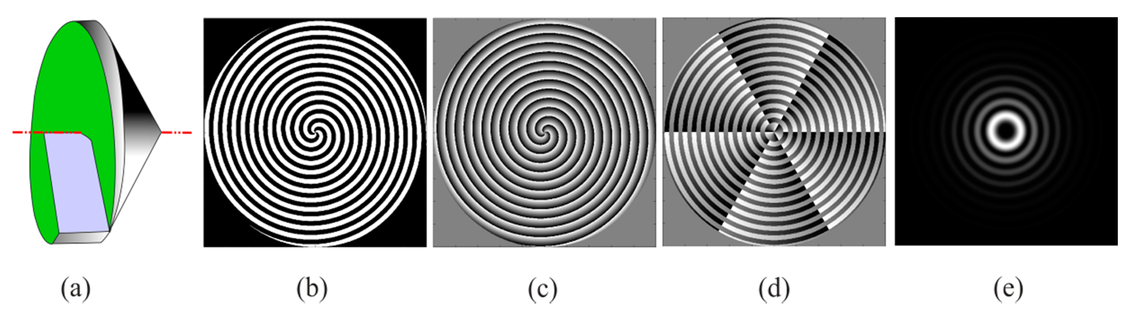
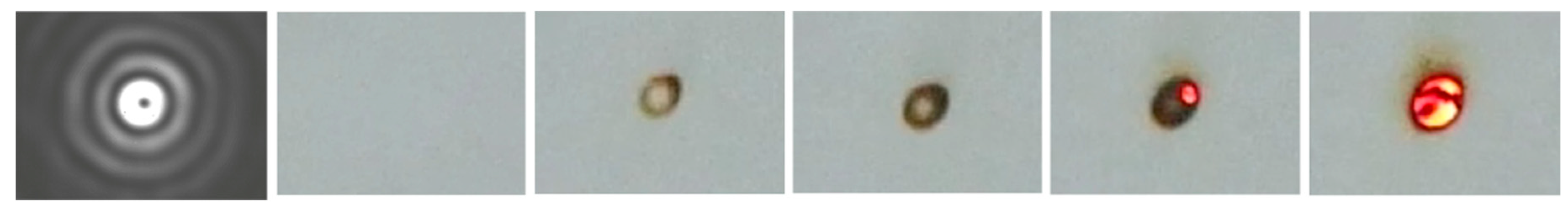
2.2. Methods of Forming Quasi-Bessel Beams

Equations (2)–(4) show how beams with properties close to those of ideal Bessel beams can be formed in real life. Here, we will call them quasi-Bessel beams (QBBs). To this end, it is necessary to use conically converging beams. A zero-order Bessel beam, for example, is formed behind an axicon (conical lens) illuminated by a beam with a plane wavefront. If a spiral phase plate is added to the axicon [13], then a higher-order Bessel beam can be formed (Figure 1a). The phase transmission function of such a hybrid element, which can be called a spiral axicon (SA), is described by the expression
t S A ( r , φ ) = k α r ( n 1 ) + φ φ κ r ,
where α is the cone-apex angle, and n is the refractive index of the material. Such axicons were fabricated using a 3D printer to generate Bessel beams at a radiation frequency of 0.3 THz in [18]. Since we are interested in radiation frequencies that are an order of magnitude higher and greater radiation powers, such volumetric plastic elements cannot be used because of the strong absorption of radiation and thermal destruction of plastic (see Figure 8 in [14]). In additions, the elements have the drawback of the ability to operate only at one given wavelength.
This problem can be solved by forming quasi-Bessel beams via the use of phase diffraction gratings with a given phase shift distribution, which are also called diffractive axicons [17]. Figure 1b–d presents three types of diffractive axicons. The phase function of a binary axicon (BA) is described by a stepwise profile
Φ B A ( r , φ ) = π 2 sign ( sin ( φ κ r ) ) ,
where
sign ( x ) = { + 1 x > 0 0 x = 0 1 x < 0 ,
and p = 2 π / κ is the axicon period.
A kinoform axicon (KA), as seen in Figure 1c, differs from the previous one in the fact that within each period, the phase incursion decreases linearly along the radius by the value 2 π
Φ K A ( r , φ ) = φ κ ρ 2 π fix ( φ κ ρ 2 π ) ,
where the function fix ( z ) converts a real number into an integer, discarding the fractional part. Essentially, this axicon is a diffractive analogue of a refractive spiral axicon (SA) (see Equation (5)).
Another axicon, which we, following [23], will call the holographic axicon (HA), has a profile that is step-wise in radius, but continuous in azimuth (Figure 1d). The width of the zones of this axicon, unlike the previous ones, is not constant, but is determined by the position of the zeros of the Bessel function [24]. In our notation, this function can be written as follows:
Φ H A ( r , φ ) = ( φ + π + H ( J | | ( κ r ) ) π / | | ) 2 π fix ( ( φ + π + H ( J | | ( κ r ) ) π / | | ) 2 π ) .
This expression is derived from (5), but the spiral plate is divided into zones along the radius. The zones are between the zeroes of a Bessel function of a given order, in which the point of reference for the azimuth angle φ , which is an argument of the function Φ ( r , φ ) , is shifted by Δ φ = π / | | for odd zones using the Heaviside function
H ( x ) = sign ( x ) + 1 2 = { + 1 x > 0 0.5 x = 0 0 x < 0 .
For the sign of the beam topological charge to change, the transparency must be rotated through 180 degrees about the axis lying in the plane of the diffractive element and passing through its center.
All the elements described above make it possible to form QBBs with the same intensity distribution in the cross-section, which coincides well with the Bessel function, and a phase function that corresponds to the exponent in Equation (1), but exists only on a certain limited length (after which they collapse):
Z * = D / 2 tan ( θ k ) D / 2 θ k ,
where D is the diameter of the element. Hereinafter, we will assume that the angles θ k are small. In this case, beam propagation can be described in the approximation of the scalar theory of diffraction. The so-calculated intensity distribution over the beam cross-section for the case of = 3 is shown in Figure 1e. Hence, we can conclude that diffractive axicons can be used in any optical systems in which it is required to form Bessel beams whose cross-section practically does not differ from that of the ideal BBs. Later on, however, we will see that a more detailed analysis reveals important differences in the characteristics of these beams.
Let us now discuss the technical side of the issue. In the visible range, phase transparencies can be generated, as discussed in the introduction, using commercially available spatial light modulators (SLMs) based on liquid crystals, whereas in the long-wave range, it is necessary to make optical elements from plastic or other materials transparent in this range. In the mid-infrared and near-terahertz ranges, materials absorb more strongly, and making helicoidal axicons with a continuous or step-wise profile requires the use of complicated technologies (multistep photolithography or laser ablation [25]). In addition, high-power free-electron lasers and wavelength-tunable sources of mid-infrared and terahertz radiation require elements with high radiation resistance and that are capable of operating with the radiation wavelength tuned within several tens of a percent. Hence, subject to the above requirements, binary axicons (Figure 1b) made of high-resistance silicon are the most suitable (at least in the first experiments). This work will mostly address these axicons. Bessel beams with an OAM (vortex beams) in the terahertz range were first obtained using such axicons [26].

2.3. Transformation of Quasi-Bessel Beams into “Perfect Vortex Beams”

As follows from expression (1), the diameters of the rings of Bessel beams grow with the topological charge . For some applications, for example, when radiation is input into dielectric fibers, this property is a disadvantage. In the case of Bessel beams, the problem can be solved by transforming them using a lens. From (1)–(4), it follows that, regardless of the magnitude and sign of the topological charge, if the beams have the same transverse wave number κ , they form an annular beam of the radius
R f f κ k z κ k ( 1 + κ 2 2 k 2 ) f κ k f
in the focal plane of the lens, the beam topological charge being equal to the charge of the initial beam. Such beams are usually called “perfect vortex beams” [14]. The amplitude-phase distribution in the real “perfect vortex beams”, however, depends on the method used to create the “parent” quasi-Bessel beam. In [27], the authors showed that the radius and width of the ring of ideal beams obtained by focusing of Bessel–Gaussian beams increased with the topological charge and demonstrated that in experiments at a wavelength of 623 nm.

3. Analytical Expressions for Vortex Beams Formed with Binary Axicons

3.1. Optical Scheme and Coordinate Sysem

For the reader to understand the meaning of the calculations performed in this section, as well as the characteristics of axicons and wavelengths selected for numerical examples, we present here a diagram of the experimental setup (Figure 2) for which these calculations are carried out. A linearly polarized Gaussian beam I = I 0 exp ( 2 r 2 / w 2 ) from the Novosibirsk free electron laser (NovoFEL) with a plane wavefront (wavelength of 141 μm and mode radius w = 11 mm) enters the user station through two radiation-resistant tungsten wire polarizers (P), the characteristics of which are described in [28]. The first polarizer is to regulate the beam power, and the second polarizer provides vertical polarization of the beam. Then, the beam passes through the beam polarization converter, which forms a vector beam [29] with the radial direction of polarization. In the experiments, the vector beam is formed using a Mach–Zehnder interferometer [30] or a segmented half-wave plate [31]. The laser radiation is an infinite train of 100-ps pulses with a repetition rate of 5.6 MHz. The average power of the NovoFEL Gaussian beam in the experiments is 50–100 W. Even after 50% attenuation of the beam because of the Fresnel reflection on the axicon, the beam energy was sufficient to fire a paper sheet, which was also partially transparent for terahertz radiation, in several seconds (Figure 3). Preliminary experiments showed that after the vector beam passed through the BA and the lens, an annular beam was formed at the lens focus, which retained its radial polarization.

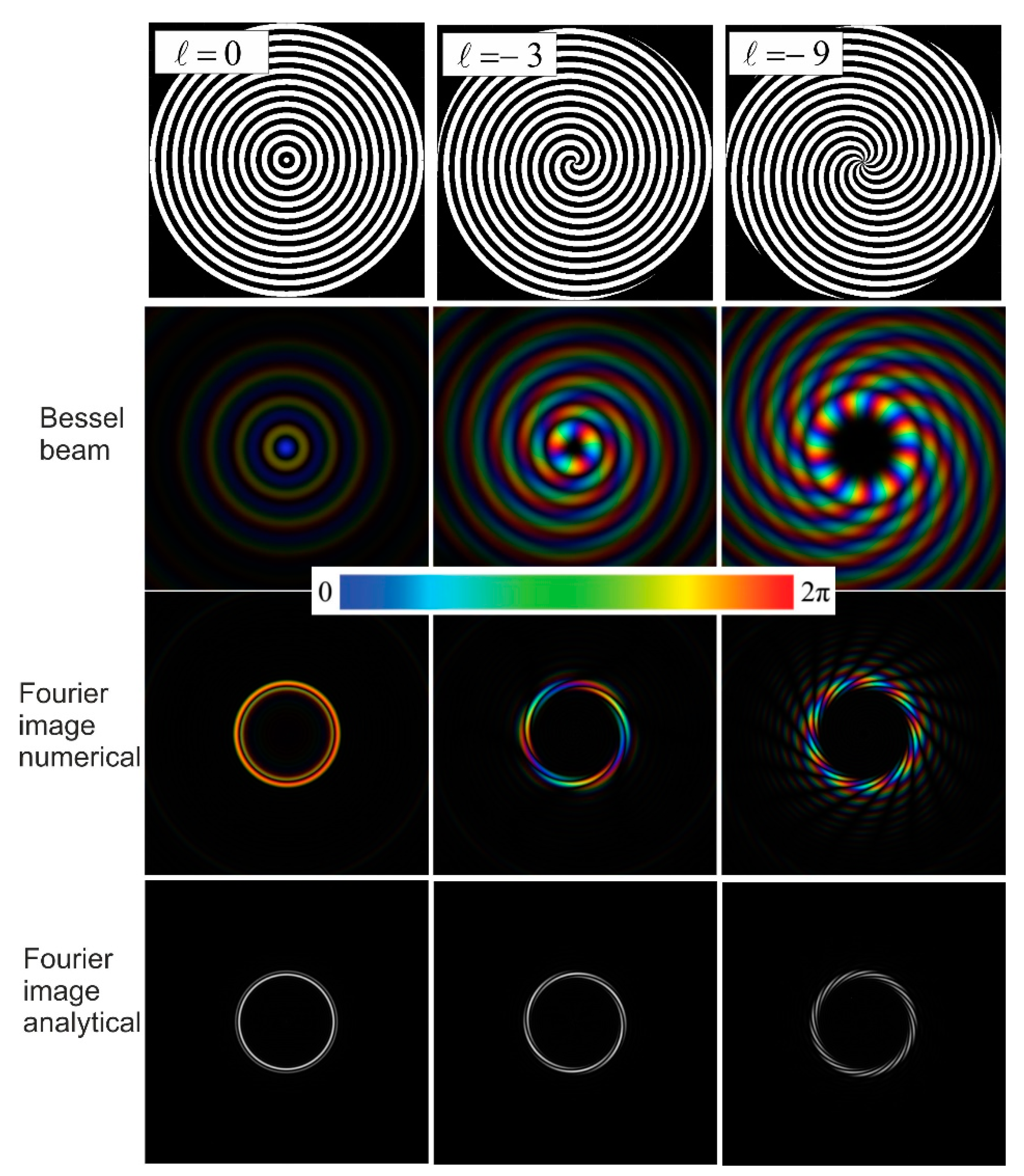
3.2. Vortex Beams behind Binary Axicon

In [26], the authors used binary phase axicons similar to that shown in Figure 1b to form Bessel beams of the first and second orders in the terahertz range. The cross-section of one of these beams, which was recorded using a microbolometer array detector, is shown in Figure 3. In [26], it was shown analytically that the electric field of a wave at a distance z behind the axicon can be written in the paraxial approximation as
E ( z , ρ , θ ) = 4 k π z ( i ) e i k ( z + ρ 2 / 2 z ) × 0 a J ( k z r ρ ) sin [ ( κ r θ ) ] e i k r 2 / 2 z r d r .
Hereinafter, we use the coordinate system shown in Figure 2. We employed the polar coordinates ( r , φ ) for the axicon plane and the coordinates ( ρ , θ ) in the space behind the axicon and in the lens plane. The upper limit of the integral is the axicon radius a .
As shown above, the region of existence of quasi-Bessel beams is determined by expression (11). A simplified analytical expression for the electric field of the Bessel beam was derived from (13) for the region a < < z < z A ( z A = k a / κ ) :
E ( z , ρ , θ ) 2 κ π ( i ) 1 2 π i z k e i θ + i k ( z + ρ 2 / 2 z ) i κ 2 z / 2 k J ( κ ρ ) ,
and for the intensity:
I ( z , ρ , θ ) J 2 ( κ ρ ) 8 κ 2 z π k .
One can see that the cross-section of the beam intensity exactly corresponds to the Bessel function. The analytical calculations in [19] were finished on this expression, and further results were obtained using numerical simulations and experiments. Since in this work, we are interested in the excitation of plasmons by means of diffraction of radiation on an end face of a cylindrical conductor, it is useful to derive, as an intermediate stage, analytical expressions for beams illuminating such a conductor. In the next section, we will find analytical expressions for converting beams described by expression (13) using a lens. Since the lens diameter is approximately equal to the axicon radius a , which is much larger than the diameter of the first rings of the Bessel beam, in the further calculations, we used expression (13), which does not contain further simplifications, as an initial expression for the wave illuminating the lens.

3.3. Transformation of Bessel Beams Formed by Binary Axicons into Perfect Vortex Beams Using a Lens

Below is the expression for a beam that has passed through a thin lens with a focal distance f [16,32]:
E ( z , r , ψ ) = i k e i k z 2 π z e i k r 2 2 z 0 a L 0 2 π ρ d ρ d θ E ( z L , ρ , θ ) e i k ρ 2 2 ( 1 z 1 f ) e i k ρ r z cos ( θ ψ ) ,
where E ( z L , ρ , θ ) is the amplitude of the wavefield incident on the lens and a L is the lens radius. Placing a thin lens at the distance z = z L from the axicon and taking into account the fact that k κ 2 / 2 k k z , after some transformations, we get the following expression at the distance z behind the lens:
E ( z , r , ψ ) = ( i ) 2 + 1 4 k 2 π z z L e i k ( z + z L + r 2 2 z ) × × 0 a L ρ d ρ J ( k ρ r z ) e i k ρ 2 2 ( 1 z L + 1 z 1 f ) { 0 a J ( k z L r ρ ) sin ( κ r ψ ) e i k r 2 / 2 z L r d r }
Here, r and ψ are the polar coordinates in the plane of the lens and a L is the radius of the lens. Since
F 1 ( r , ρ , r ) = 0 2 π sin [ ( κ r θ ) ] e i k ρ r z cos ( θ ψ ) d θ = 2 π ( i ) J ( k ρ r z ) sin ) κ r ψ ) ,
we have
E ( r , ψ , z ) = = ( i ) 2 1 4 k 2 e i k ( z + Z L + r 2 / 2 z ) π z Z L 0 a { 0 a L J ( k ρ r z ) J ( k Z L r ρ ) e i k ρ 2 2 [ 1 Z L + 1 z 1 f ] ρ d ρ } sin ( κ r ψ ) e i k r 2 / 2 Z L r d r
Making a trivial substitution ρ 2 = x in the integral with respect to ρ , introducing the variable Z L f = ( 1 / z L + 1 / z 1 / f ) 1 , and expanding the upper limit of integration a L to infinity, we get the following integral, the value of which is given in [33] (see Appendix A):
F 2 ( r , r ) = 0 [ J ( k z L r ρ ) J ( k ρ r z ) e i k ρ 2 2 Z L f ] ρ d ρ = 1 2 0 [ e i x ( k / 2 Z L f ) J ( x k r z ) J ( x k r z L ) ] d x = = i Z L f k I ( i Z L f k r r z z L ) exp { i Z L f k 2 [ ( r z L ) 2 + ( r z ) 2 ] } = = i + 1 Z L f k J ( Z L f k r r z z L ) exp { i Z L f k 2 [ ( r z L ) 2 + ( r z ) 2 ] } .
Substituting the resulting expression (20) into (19), we obtain the final expression for the field behind the lens:
E ( z , r , ψ ) = ( i ) 4 k Z L f π z z L e i k ( z + z L + r 2 2 z Z L f r 2 2 z 2 ) × 0 a J ( Z L f k r r z Z L ) e i k Z L f r 2 2 z L 2 sin ( κ r ψ ) e i k r 2 / 2 z L r d r
For the distance z = f, which is the main interest to us, we get the field amplitude
E ( f , r , ψ ) = ( i ) 4 k π f e i k r 2 2 f ( 1 z L f ) × 0 a J ( k r r f ) sin ( κ r ψ ) r d r ,
where we omitted the insignificant constant phase factors in the exponent. The integrals in expressions (21) and (22) cannot be taken analytically; therefore, further calculations (see below) will be performed numerically. Based on the law of conservation of angular momentum, one can assume that the beam behind the lens has the same topological charge as the quasi-Bessel beam created by the axicon. In expressions (21) and (22), this dependence is hidden in the harmonic term under the integral (compare with Equation (5)).

3.4. Perfect Vortex Beams: Graphical Representation

As already mentioned in Section 3.1, Bessel beams formed by diffractive axicons have features that are not manifested in the intensity distribution, but are present in the phase distribution. When the beams are transformed by a lens, which is a Fourier transformer, these features are manifested in the spatial distribution too. Since our next task will be excitation of surface plasmon polaritons using perfect beams, the efficiency of plasmon excitation will depend on the features of the amplitude–phase distribution in the beams. In Figure 4, we present graphs of the distributions of fields and intensities in the lateral and longitudinal sections of perfect beams with the topological charges = 0 , 1 , 2 constructed based on Equations (21) and (22). Together with the plots for the Bessel beams presented in [26], they can serve as a useful reference for planning experiments with binary phase axicons. It is seen from the figure that in the case of beams created by binary spiral axicons, the intensity distribution at the focus is much more complicated than that for the ideal “perfect beams” (12). Instead of a single ring, we see (Figure 4a,b) a structure of nested rings (at = 0 ) or nested segments of spirals (at | | > 0 ). However, most energy is concentrated in the annular region corresponding to the radius R f . In Figure 4a, the direction of the twisting of the spirals corresponds to beams with a negative topological charge when the observer looks along the axis z .
Figure 4c shows the effect of the diffraction of beams because of the limited beam diameter. It is seen that the beam cross-section is not symmetric with respect to the focal plane. This feature can be used for adjustment of the diameter of the “perfect beam” to the diameter of the conductor on which surface plasmon polaritons are to be excited. The phase distribution in the ring is also quite complex and can affect the efficiency of SPP generation.

4. Comparison of Wavefields of “Perfect Beams” and SPPs

4.1. Characteristics of SPPs on Axisymmetric Conductors

In this section, we will discuss the features of plasmon excitation by the end-fire coupling technique [13], which we must take into account when evaluating the applicability of one or another axicon for this. Surface plasmon polaritons [34] are essentially coupled oscillations of electrons in the surface layer of a conductor and a p-polarized electromagnetic field in an adjacent dielectric, which propagate along the surface. The field strength goes down on both sides of the interface, and the wave energy decreases due to ohmic losses in the conductor. In the case of cylindrical geometry, the normal component of the plasmon field value F ( r ) decreases according to the law (see, e.g., [35])
F ( r ) = { I 1 ( p m r ) I 1 ( p m a w ) r < a w K 1 ( p d r ) K 1 ( p d a w ) r > a w ,
where I 1 ( ) and K 1 ( ) are modified first-order Bessel functions of the first and second kind, respectively, p m , d = k s 2 k 0 2 ε m , d and ε m , d are the dielectric permittivities of the metal and dielectric, respectively, k s is the wave vector of plasmon, and a w is the radius of the cylinder.
Our prime interest is the efficiency of the excitation of the plasmon that rotates while propagating along a conductor with a frequency determined by the orbital angular momentum of the exciting beam; therefore, as a model of a plasmon, we will choose an electromagnetic wave that has the following field distribution over the surface
F ( z , r , ψ ) = K 1 ( p m r ) K 1 ( p m a w ) e i ψ e γ ( z f ) , r > a w
and carries an orbital moment corresponding to the moment of the exciting wave. Here, γ is the decay constant of the amplitude of the surface wave during the propagation of the plasmon along the cylinder. In the terahertz range, for metals such as copper and gold, the plasmon propagation length varies from centimeters to tens of centimeters [34], that is, by an order of magnitude; the attenuation coefficient of the surface wave along the z-axis is 10−2 mm−1. With a conductor diameter of several millimeters, the electric field decays almost exponentially with respect to the radius:
F ( z , r , ψ ) = e β ( r a w ) e i ψ e γ ( z f ) .
In this case, the decay constant β must be close to the respective value for plasmons on flat surfaces. For a gold surface with a zinc sulfide coating that is 0 to 1.5 µm thick, the measured β values are in the range of 0.3 ÷ 5 mm–1 [36]. According to experiments [37], the optimal thickness of the dielectric coating, which ensures good coupling of the plasmon with the surface and reduces parasitic radiation losses, is approximately 1 μm. In this case, the characteristic decay length for the evanescent wave in air is approximately 200–300 μm, that is, practically all energy of the plasmon field is concentrated within a cylindrical layer that is less than 0.6 mm thick.

4.2. Wavefields of Perfect Beams Obtained with Binary Axicons and Overlap Integral

In waveguide systems, the efficiency of the transformation of the exciting wavefield into a waveguide mode is usually estimated by the value of the overlap integral of the incident wavefield and the waveguide mode field (see, for example, [38]). The closer the distribution of the incident wave amplitude and phase to the expected distribution of these quantities in the waveguide mode, the greater the efficiency of excitation of the latter. Let us write the overlap integral for our case. It is known that the electric field of a plasmon on a cylinder has both radial and longitudinal components, while the incident wave at the lens focus has a plane wavefront; therefore, it is more convenient to write the overlap integral through the vectors of the magnetic field, which, in both cases, has only azimuthal components:
d η ( ψ ) d ψ [ a w H ψ ( S P P ) ( r , ψ ) H ψ ( Q B B ) * ( r , ψ ) r d r ] 2 [ a w H ψ ( S P P ) ( r , ψ ) H ψ ( S P P ) * ( r , ψ ) r d r ] [ a w H ψ ( Q B B ) ( r , ψ ) H ψ ( Q B B ) ( r , ψ ) r d r ] .
Unlike the notation conventional for the bulk waves, as, for example, in [39], we write here not the total efficiency of the transformation of a free wave into a plasmon mode, but its derivative as a function of the azimuthal angle. This notation takes into account the difference between the excitation of a waveguide mode, for example, in a resonator, and the excitation of a plasmon on a surface. In the first case, the excited mode is spatial, and its distribution across the entire volume is known in advance. All the energy absorbed transmits into this mode. In the case of plasmons, the situation is different. A plasmon is excited at the conductor edge and moves in a certain direction. Simultaneously, another plasmon moving in parallel can be excited nearby with the same field distribution, but, generally speaking, with a different intensity, set by the local pumping intensity. In other words, in the first approximation, the excitation of plasmons in different regions can be considered independent. This is evidenced by the observation of parallel non-expanding tracks of plasmons created by the diffraction of a Bessel beam at the edge of a convex surface [40].
To calculate expression (27), one should substitute the expected distribution of the plasmon field in the air, and the field of the vortex beam illuminating the end of the cylinder should be substituted into it. The plasmon field is described by the expression F ( f , r , ψ ) = e β ( r a w ) e i ψ , where the β value can be taken from the experimental data for the Au–ZnS–air surface [34], and the incident wavefield can be calculated according to (22). Figure 5 shows the intensity and phase distributions in the Bessel beams generated by binary axicons and in perfect beams in the focal plane of the lens. The numerical calculations were carried out using the diffraction integral [41], whereas the analytical calculations were done using Equation (22). The results of the calculations are very similar. The parameters of the axicons were selected in a way such that the diameter of the beams at the focus of the lens was approximately 7 mm, which is close to the diameter of the cylindrical conductors prepared for experiments. One can see that the width of the brightest part of the ring is about 0.6 mm, which is in good agreement with the plasmon decay length estimated above. The wavefields of perfect beams produced by binary axicons of different orders (see Figure 5) have variations of brightness over the azimuthal angle, which has a number equal to 2 . Thus, we can expect the generation of 2 parallel SPPs on a cylinder if the topological charge of a perfect beam is equal to .

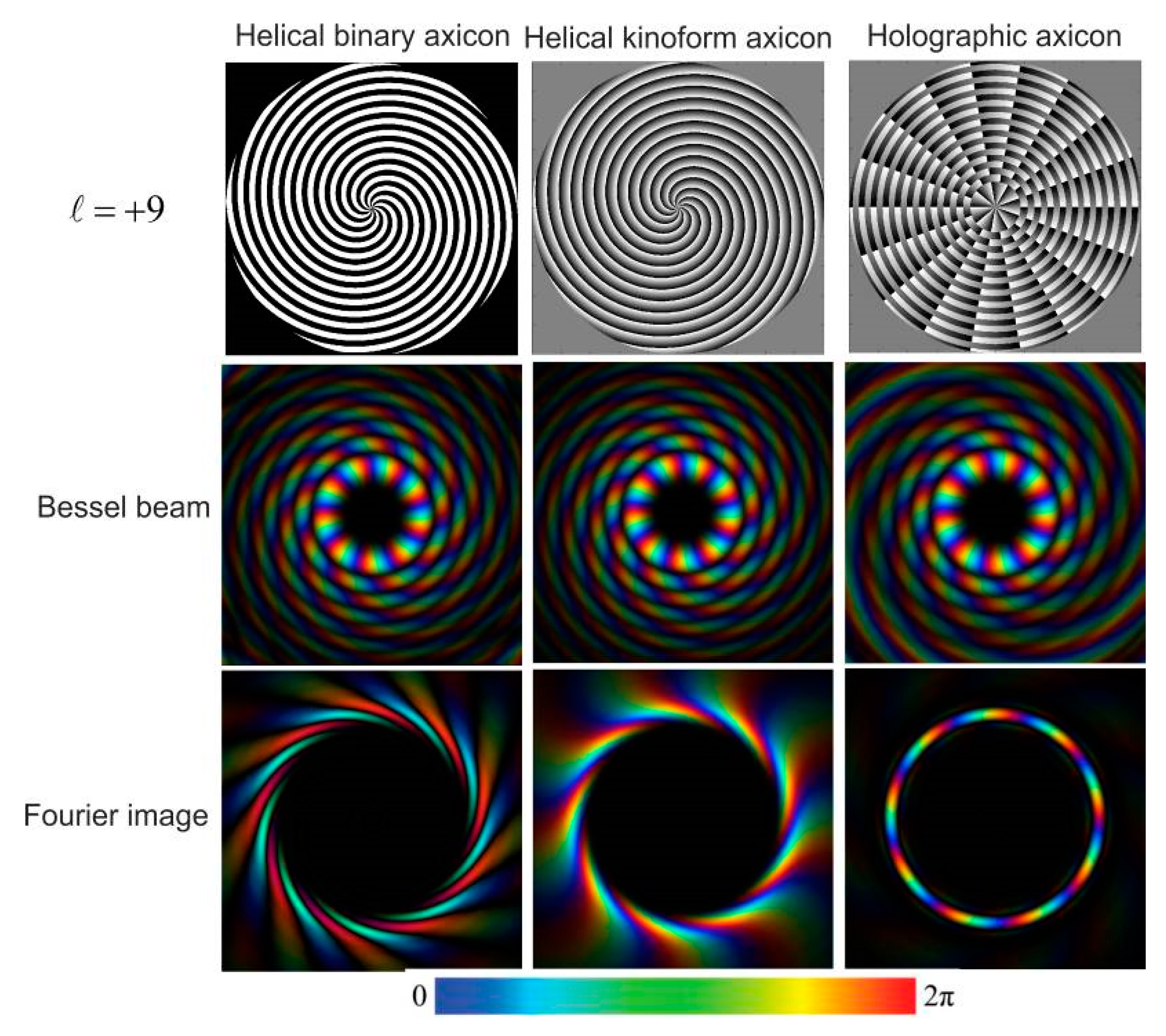
4.3. Comparison of Perfect Beams Generated with Different Axicons

Since the field distributions in “perfect beams” created by binary axicons are quite far from ideal rings, we calculated the fields of Bessel beams and their images in the focal plane of a lens for all three axicons within the scalar diffraction theory. The calculation results are shown in Figure 6.
As seen from the third row in Figure 6, the calculated value of the ring radius in the focal plane of a lens with f = 100 mm for an ideal Bessel beam with a transverse wavenumber κ = 3.1 (see Equation (4)) is 6.9 mm. The inner radius of all three rings in the figure is 6.6 mm. The radius of the maximum intensity of the ring created using the holographic axicon coincides well with the calculated value of 6.9 mm. The rest of the rings are much wider, and the numbers of spiral segments they have are 9 and 18, respectively. Using these results and adding to them the results of calculations for the same axicons with a topological charge of 3, we collected in Figure 7 the cross-sections of perfect beams produced with different axicons. Now, we summarize in Table 1 the main characteristics of perfect beams created using different types of axicons and discuss the results obtained.

5. Discussion

The results of the analytical and numerical calculations of the characteristics of terahertz vortex beams created by the three types of axicons show that their characteristics depend substantially on the axicon type. Although all these axicons create quasi-Bessel beams, in which the amplitude–phase distributions of the field in the first ring are almost identical, the distributions of the field at the periphery differ—insignificantly, at first glance. However, when a lens focuses these beams, the main contribution into the formation of perfect beams, which are essentially the Fourier transform of a quasi-Bessel beam, is made by the beam periphery, in which the energy significantly exceeds the energy contained in the first ring. As a result, as seen in Figure 5, Figure 6 and Figure 7 and Table 1, the shape of the annular PVB is highly dependent on the phase distribution profile of each axicon. The diffraction phenomena associated with the relatively small number of zones in the axicons, which should be rather wide in the terahertz range because of the large wavelength, may also play a certain role in the formation of the PVB profile.
From this, we can draw two conclusions. First, perfect beams formed in different experiments always bear the imprint of their origin, and the properties of each of them are largely individual. The second concerns the Bessel beams themselves. It is very likely that their inherent self-recovery property after passing through inhomogeneities also depends on their origin, since self-recovery is provided by the arrival of converging plane waves from the beam periphery into the optical axis region. Apparently, this circumstance should be taken into account in propagation of Bessel beams in inhomogeneous media.
Another issue to discuss is the dependence of PVB parameters on the magnitude of the topological charge. In [27], it was shown theoretically and experimentally that, in contrast to the conclusions of the simplified theory, the radius and width of the rings of PVBs created in the visible range using a spatial light modulator grow with the topological charge. The results of our calculations show that in the case of terahertz vortices created using diffraction axicons, we observe no strong dependence on the topological charge, although there is a slight upward trend. We can trust the accuracy of calculations by this program, since, in [26], it was demonstrated that the images of perfect beams obtained in the experiment coincided with the calculated ones.
In conclusion, let us discuss the possibilities of using axicons to excite surface plasmon polaritons on cylindrical waveguides. A factor favorable for the excitation of terahertz plasmons is the very small change in the radius and width of the rings of perfect plasmons with a change in the topological charge. Apparently, radially polarized PVBs can be applied to the excitation of azimuth-uniform SPPs using a holographic axicon. In this case, the half-width of the PVB ring is approximately 400 μm, which is in good agreement with the decay length of plasmons on a gold surface covered with a zinc sulfide layer that is about 0.5 μm thick. When using other axicons, one can expect the separation of SPPs in azimuth into or 2 plasmons moving in parallel, which, however, carry the same total orbital angular momentum. Since in this case, the half-width of the rings is of the order of 1 mm, they can be used at a dielectric coating thickness of about 0.1 μm, at which the decay length is close to this value. With linear polarization of the PVB, plasmons will be excited on the opposite sides of the cylinder, where the wave electric field vector is normal to the surface. Finally, note that the limited aperture of the beam on the axicon, which causes diffraction of the beam, can also be beneficial in experiments. Figure 4 shows that near the focal plane, the ring diameter changes smoothly; by moving the end face of the cylinder along the axis, one can optimize the efficiency of the plasmon excitation due to change in the overlap integral value (27).

Author Contributions

B.K. (supervision, analytical calculations, calculations in Mathcad, writing the article, and editing); V.C. (analytical calculations, calculations in Mathematica, visualization, and writing the article); O.K. (calculations in Matlab, simulation of vortex beam diffraction, and writing the article). All authors have read and agreed with the published version of the manuscript.

Funding

This research was funded by the Russian Science Foundation, grant 19-12-00103. The experimental results cited in the article were obtained in the experiments carried out at the shared research center SSTRC based on the Novosibirsk FEL complex [42] at BINP SB RAS, using equipment supported by the project RFMEFI62119X0022.

Acknowledgments

The authors thank V.S. Pavelyev and M.S. Komlenok for the useful discussions and close cooperation in the field of diffractive optics.

Conflicts of Interest

The authors declare no conflict of interest.

Appendix A

Strictly speaking, according to [33], relation (20) holds only if the real part of the exponent in the original integral is negative. Numerical calculations using the Matematica package have shown that the relation is also valid for a purely imaginary exponent. The use of this formula greatly simplified our solution, but there appeared a problem of validity of this replacement.
The point is that the handbook presents Formula (20) with an infinite upper limit, while in Formula (19), this integral is calculated with a finite upper limit. Since comparing two functions with two external parameters ( r and r ) is an extremely resource-intensive and ambiguous problem, we checked the admissibility of such a replacement not by comparing the integral from (19) with Formula (20), but by matching the graphs of the dependence of the radiation intensity in the focal plane of the lens, i.e., the results of numerical integration of original Formula (17) and calculations with Formula (21). The results are shown in Figure 4. They evidence that the use of solution (20) is justified, at least in our case.
Figure A1. Rings of perfect vortex beams: comparison of exact calculations with Formula (17) (solid line) and approximate calculations with Formula (21) (dots): (a) = 1 ; (b) = 2 .
Applsci 11 00717 g0a1

References

  1. Padgett, M.J. Orbital angular momentum 25 years on [Invited]. Opt. Express 2017, 25, 11265–11274. [Google Scholar] [CrossRef] [PubMed]
  2. Knyazev, B.A.; Serbo, V.G. Beams of photons with nonzero orbital angular momentum projection: New results. Physics-Uspekhi 2018, 61, 449–479. [Google Scholar] [CrossRef]
  3. Lee, S.-Y.; Park, J.; Kim, H.; Cho, S.-W.; Lee, B. Controlling the state of surface plasmon vortex by changing the topological charge and polarization state. In Proceedings of the Plasmonics: Metallic Nanostructures and Their Optical Properties VIII, Bellingham, WA, USA, 10 September 2010; International Society for Optics and Photonics: Bellingham, WA, USA; Volume 7757, p. 77573G. [Google Scholar]
  4. Kim, H.; Park, J.; Cho, S.-W.; Lee, S.-Y.; Kang, M.; Lee, B. Synthesis and dynamic switching of surface plasmon vortices with plasmonic vortex lens. Nano Lett. 2010, 10, 529–536. [Google Scholar] [CrossRef] [PubMed]
  5. Cho, S.-W.; Park, J.; Lee, S.-Y.; Kim, H.; Lee, B. Coupling of spin and angular momentum of light in plasmonic vortex. Opt. Express 2012, 20, 10083–10094. [Google Scholar] [CrossRef] [Green Version]
  6. Mei, S.; Huang, K.; Liu, H.; Qin, F.; Mehmood, M.Q.; Xu, Z.; Hong, M.; Zhang, D.; Teng, J.; Danner, A.; et al. On-chip discrimination of orbital angular momentum of light with plasmonic nanoslits. Nanoscale 2016, 8, 2227–2233. [Google Scholar] [CrossRef]
  7. Wang, S.; Zhao, C.; Li, X. Dynamical manipulation of surface plasmon polaritons. Appl. Sci. 2019, 9, 3297. [Google Scholar] [CrossRef] [Green Version]
  8. Zhang, X.; Xu, Q.; Xia, L.; Li, Y.; Gu, J.; Tian, Z.; Ouyang, C.; Han, J.; Zhang, W. Terahertz surface plasmonic waves: A review. Adv. Photon. 2020, 2, 014001. [Google Scholar] [CrossRef]
  9. Knyazev, B.A.; Kameshkov, O.E.; Nikitin, A.K.; Pavelyev, V.S.; Choporova, Y.Y. Feasibility of generating surface plasmon po-laritons with a given orbital momentum on cylindrical waveguides using diffractive optical elements. Comput. Opt. 2019, 43, 992–1000. [Google Scholar] [CrossRef]
  10. Willner, A.E.; Huang, H.; Yan, Y.; Ren, Y.; Ahmed, N.; Xie, G.; Bao, C.; Li, L.; Cao, Y.; Zhao, Z.; et al. Optical communications using orbital angular momentum beams. Adv. Opt. Photon. 2015, 7, 66–106. [Google Scholar] [CrossRef] [Green Version]
  11. Dawson, P.; Puygranier, B.A.F.; Goudonnet, J.-P. Surface plasmon polariton propagation length: A direct comparison using photon scanning tunneling microscopy and attenuated total reflection. Phys. Rev. B 2001, 63, 205410. [Google Scholar] [CrossRef]
  12. Knyazev, B.A.; Choporova, Y.Y.; Gerasimov, V.V.; Kameshkov, O.E.; Nikitin, A.K.; Osintseva, N.D.; Pavelyev, V.S.; Vinokurov, N.A.; Agafonov, A.N.; Cherkassky, V.S.; et al. Experiments on Generation of vortex surface plasmon polaritons on plane and cylindrical conductors in mid-infrared and THz ranges. In Proceedings of the 45th International Conference on Infrared, Millimeter, and Terahertz Waves (IRMMW-THz), Buffalo, NY, USA, 8–13 November 2020; IEEE: Piscataway, NJ, USA (to be published). [Google Scholar]
  13. Maradudin, A.; Wallis, R.; Stegeman, G. The optics of surface and guided wave polaritons. Prog. Surf. Sci. 1990, 33, 171–257. [Google Scholar] [CrossRef]
  14. Ostrovsky, A.S.; Rickenstorff-Parrao, C.; Arrizón, V. Generation of the “perfect” optical vortex using a liquid-crystal spatial light modulator. Opt. Lett. 2013, 38, 534–536. [Google Scholar] [CrossRef]
  15. Vaity, P.; Rusch, L. Perfect vortex beam: Fourier transformation of a Bessel beam. Opt. Lett. 2015, 40, 597–600. [Google Scholar] [CrossRef] [PubMed]
  16. Goodman, J.W. Introduction to Fourier Optics; Roberts and Company Publishers: Boston, MA, USA, 2005. [Google Scholar]
  17. Soifer, V.A. Computer Design of Diffractive Optics; Elsevier: Amsterdam, The Netherlands, 2013; p. 896. [Google Scholar]
  18. Wei, X.; Liu, C.; Niu, L.; Zhang, Z.; Wang, K.; Yang, Z.; Liu, J. Generation of arbitrary order Bessel beams via 3D printed axicons at the terahertz frequency range. Appl. Opt. 2015, 54, 10641–10649. [Google Scholar] [CrossRef] [PubMed]
  19. Pavelyev, V.S.; Volodkin, B.; Tukmakov, K.N.; Knyazev, B.A.; Choporova, Y.Y. Transmissive diffractive microoptics for high-power THz laser radiation. In AIP Conference Proceedings; AIP Publishing LLC: Melville, NY, USA, 2018; Volume 1989, p. 020025. [Google Scholar] [CrossRef]
  20. Knyazev, B.A.; Choporova, Y.Y.; Pavelyev, V.S.; Volodkin, B.O.; Mitkov, M.S. High-power terahertz non-diffractive bessel beams with angular orbital momentum: Generation and application. In Proceedings of the 2015 40th International Conference on Infrared, Millimeter, and Terahertz Waves (IRMMW-THz), Hong Kong, China, 23–28 August 2015; IEEE: Piscataway, NJ, USA, 2015; pp. 1–2. [Google Scholar]
  21. Skidanov, V.E.; Ganchevskaya, S.V. Diffractive optical elements for the formation of combinations of vortex beams in the problem manipulation of microobjects. Comp. Opt. 2014, 38, 65–71. [Google Scholar] [CrossRef] [Green Version]
  22. Liu, J.; Li, Z.-Y. Controlled mechanical motions of microparticles in optical tweezers. Micromachines 2018, 9, 232. [Google Scholar] [CrossRef] [PubMed] [Green Version]
  23. Arrizón, V.; Sánchez-de-la-Llave, D.; Ruiz, U.; Méndez, G. Efficient generation of an arbitrary nondiffracting Bessel beam em-ploying its phase modulation. Opt. Lett. 2009, 34, 1456–1458. [Google Scholar] [CrossRef]
  24. Fedotowsky, A.; Lehovec, K. Optimal Filter Design for Annular Imaging. Appl. Opt. 1974, 13, 2919–2923. [Google Scholar] [CrossRef]
  25. Kononenko, T.V.; Knyazev, B.A.; Sovyk, D.N.; Pavelyev, V.S.; Komlenok, M.S.; Komandin, G.A.; Konov, V.I. Silicon kinoform cylindrical lens with low surface roughness for high-power terahertz radiation. Opt. Laser Technol. 2020, 123, 105953. [Google Scholar] [CrossRef]
  26. Choporova, Y.Y.; Knyazev, B.; Kulipanov, G.N.; Pavelyev, V.S.; Scheglov, M.A.; Vinokurov, N.A.; Volodkin, B.O.; Zhabin, V.N. High-power Bessel beams with orbital angular momentum in the terahertz range. Phys. Rev. A 2017, 96, 023846. [Google Scholar] [CrossRef]
  27. Pinnell, J.M.C.; Rodríguez-Fajardo, V.; Forbes, A. How perfect are perfect vortex beams? Opt. Lett. 2019, 44, 5614–5617. [Google Scholar] [CrossRef] [PubMed]
  28. Cherkassky, V.S.; Knyazev, B.A.; Kulipanov, G.N.; Matveenko, A.N.; Rudych, P.D.; Vinokurov, N.A. Study of polarizer char-acteristics with a high-power terahertz free electron laser. Int. J. Infrared Millim. Wave 2007, 28, 219–222. [Google Scholar] [CrossRef]
  29. Zhan, Q. Cylindrical vector beams: From mathematical concepts to applications. Adv. Opt. Photon. 2009, 1, 1–57. [Google Scholar] [CrossRef]
  30. Choporova, Y.Y.; Knyazev, B.A.; Osintseva, N.D.; Pavelyev, V.S.; Tukmakov, K.N. Two channel terahertz communication based on spatial mode multiplexing. In Proceedings of the 2019 44th International Conference on Infrared, Millimeter, and Terahertz Waves (IRMMW-THz), Paris, France, 1–6 September 2019; IEEE: Piscataway, NJ, USA, 2019; p. 1. [Google Scholar]
  31. Saito, Y.; Kobayashi, M.; Hiraga, D.; Fujita, K.; Kawano, S.; Smith, N.; Inouye, Y.; Kawata, S. z-Polarization sensitive detection in micro-Raman spectroscopy by radially polarized incident light. J. Raman Spectrosc. 2008, 39, 1643–1648. [Google Scholar] [CrossRef]
  32. Sheppard, C. Diffraction optics. In Handbook of Biomedical Optics; Boas, D.A., Pitris, C., Ramanujam, N., Eds.; CRC Press: Boca Raton, FL, USA, 2016; pp. 31–52. [Google Scholar]
  33. Magnus, W.; Oberhettinger, F.; Soni, R.P. Formulas and theorems for the special functions of mathematical physics. Grundlehren der mathematischen Wissenschaften in Einzeldarstellungen, Band 52. Formulas and Theorems for the Special Functions of Mathematical Physics, 3rd ed.; Springer: Berlin, Germany, 1966. [Google Scholar]
  34. Maier, S.A. Plasmonic: Fundamentals and Applications; Springer: New York, NY, USA, 2007. [Google Scholar]
  35. Gordon, R. Reflection of cylindrical surface waves. Opt. Express 2009, 17, 18621–18629. [Google Scholar] [CrossRef] [PubMed]
  36. Gerasimov, V.V.; Knyazev, B.A.; Lemzyakov, A.G.; Nikitin, A.K.; Zhizhin, G.N. Growth of terahertz surface plasmon propagation length due to thin-layer dielectric coating. J. Opt. Soc. Am. B 2016, 33, 2196–2203. [Google Scholar] [CrossRef]
  37. Knyazev, B.; Gerasimov, V.V.; Nikitin, A.K.; Azarov, I.A.; Choporova, Y.Y. Propagation of terahertz surface plasmon polaritons around a convex metal–dielectric interface. J. Opt. Soc. Am. B 2019, 36, 1684–1689. [Google Scholar] [CrossRef]
  38. Chang, L.; Sun, X.; Shang, H.; Liu, P.; Hall, T.J.; Sun, D. Analysis of the fiber-waveguide coupling efficiency and the resulting polarization dependent loss. In Proceedings of the 2017 International Conference on Numerical Simulation of Optoelectronic Devices (NUSOD), Copenhagen, Denmark, 24–28 July 2017; IEEE: Piscataway, NJ, USA, 2017; pp. 155–156. [Google Scholar]
  39. Edelmann, A.; Helfert, S.; Jahns, J. Shaping of electromagnetic fields for THz plasmonics. In Complex Light and Optical Forces VIII; International Society for Optics and Photonics: Bellingham, WA, USA, 2014; Volume 8999, p. 899913. [Google Scholar]
  40. Knyazev, B.; Choporova, Y.Y.; Mitkov, M.S.; Pavelyev, V.S.; Volodkin, B.O. Generation of terahertz surface plasmon polaritons using nondiffractive Bessel beams with orbital angular momentum. Phys. Rev. Lett. 2015, 115, 163901. [Google Scholar] [CrossRef]
  41. Kameshkov, O.E.; Knyazev, B.A. Simulating diffraction on a series of amplitude-phase masks for experiments at the Novosibirsk free electron laser. Bull. Russ. Acad. Sci. Phys. 2019, 83, 184–189. [Google Scholar] [CrossRef]
  42. Shevchenko, O.A.; Vinokurov, N.A.; Arbuzov, V.S.; Chernov, K.N.; Deichuly, O.I.; Dementyev, E.N.; Dovzhenko, B.A.; Getmanov, Y.V.; Gorbachev, Y.I.; Knyazev, B.A.; et al. The Novosibirsk free electron laser facility. In AIP Conference Proceedings; AIP Publishing LLC: Melville, NY, USA, 2020; Volume 2299, p. 020001. [Google Scholar]
Figure 1. Optical elements for formation of quasi-Bessel beams. (a) Spiral axicon forming a beam with a topological charge = + 1 . (bd) Phase axicons forming beams with topological charges = + 3 : binary axicon (b), kinoform axicon (c), and holographic axicon (d). All phase axicons are 50 mm in diameter and designed for operation at wavelength λ = 141 μm. (e) The calculated intensity distributions of quasi-Bessel beams with | | = 3 formed by any of the phase axicons at a distance of 120 mm are identical. The size of frame is 20 × 20 mm. In (bd), the phase grows from 0 (black) to 2 π (white).
Applsci 11 00717 g001
Figure 2. Optical system for launching vortex surface plasmon polaritons on a cylindrical conductor.
Applsci 11 00717 g002
Figure 3. Image of a quasi-Bessel beam formed with a binary axicon and recorded by a microbolometer detector array (compare with Figure 1e). Right: sequence of video frames demonstrating firing paper with this beam. In this case, no polarization converter was used, and the beam had linear polarization. Frame dimensions were 16.32 × 12.24 mm2.
Applsci 11 00717 g003
Figure 4. Distribution of intensity I ( r , ψ , z ) = E ( r , ψ , z ) E ( r , ψ , z ) of vortex beams with = 0 , 1 , 2 (left, middle, and right columns, respectively) created by binary axicons with periods p = 3.1 mm in the space behind the lens with focal length f = 100 mm. Dimensions are in millimeters. (a,b) Distribution of I ( r , ψ , f ) in the focal plane of lens, calculated by Formula (22). (c) Longitudinal section of the same beam I ( r , 0 , z ) for 80 z 120 mm, calculated using Formula (21). The radiation wavelength is 141 μm.
Applsci 11 00717 g004
Figure 5. Top row: helical binary axicons for generation of quasi-Bessel beams of different topological charges ( D = 50 mm, p = 2.03 mm ( κ = 3.1 mm−1), Z L = 120 mm). Second row: Bessel beam intensity distributions; phase distributions are shown with a color map ( λ = 141 μm). Third and fourth rows: perfect beams in a lens focal plane ( f = 50 mm), simulated numerically and calculated using Equation (22). Frame size is 20 × 20 mm2.
Applsci 11 00717 g005
Figure 6. Top row: binary, kinoform, and holographic axicons for generation of quasi-Bessel beams with topological charge = + 9 ( D = 50 mm, ( κ = 3.1 mm−1), Z L = 120 mm). Middle row: Bessel beams’ intensity distributions; phase distributions are shown with a color map ( λ = 141 μm). Bottom row: the same for a lens focal plane (f = 100 mm). Frame size is 20 × 20 mm2.
Applsci 11 00717 g006
Figure 7. Calculated cross-sections of rings of perfect beams for three types of axicons and two values of topological charge ( f = 100 mm). For other parameters, see Figure 6.
Applsci 11 00717 g007
Table 1. Calculated ring parameters of perfect beams formed by three types of axicons producing quasi-Bessel beams with κ = 3.1 mm−1 at a wavelength of 141 μm: is the topological charge of the vortex beam, R max is the position of the ring maximum, and Δ R is the ring half-width.
Axicon TypeBinaryKinoformHolographic
393939
R max , mm7.057.46.957.07.057.4
Δ R , mm~25~250.821.050.410.43
Publisher’s Note: MDPI stays neutral with regard to jurisdictional claims in published maps and institutional affiliations.

