Article

An Adaptive Model Predictive Voltage Control for LC-Filtered Voltage Source Inverters

Department of Energy Technology, Aalborg University, 9220 Aalborg, Denmark
*
Author to whom correspondence should be addressed.
Appl. Sci. 2021, 11(2), 704; https://doi.org/10.3390/app11020704
Submission received: 14 December 2020 / Revised: 4 January 2021 / Accepted: 9 January 2021 / Published: 13 January 2021

Abstract

:
The three-phase inductor and capacitor filter (LC)-filtered voltage source inverter (VSI) is subjected to uncertain and time-variant parameters and disturbances, e.g., due to aging, thermal effects, and load changes. These uncertainties and disturbances have a considerable impact on the performance of a VSI’s control system. It can degrade system performance or even cause system instability. Therefore, considering the effects of all system uncertainties and disturbances in the control system design is necessary. In this respect and to tackle this issue, this paper proposes an adaptive model predictive control (MPC), which consists of three main parts: an MPC, an augmented state-space model, and an adaptive observer. The augmented state-space model considers all system uncertainties and disturbances and lumps them into two disturbance inputs. The proposed adaptive observer determines the lumped disturbance functions, enabling the control system to keep the nominal system performance under different load conditions and parameters uncertainty. Moreover, it provides load-current-sensorless operation of MPC, which reduces the size and cost, and simultaneously improves the system reliability. Finally, MPC selects the proper converter voltage vector that minimizes the tracking errors based on the augmented model and outputs of the adaptive observer. Simulations and experiments on a 5 kW VSI examine the performance of the proposed adaptive MPC under different load conditions and parameter uncertainties and compare them with the conventional MPC.

1. Introduction

Nowadays, three-phase inductor and capacitor (LC)-filtered voltage source inverters (VSIs) have found widespread applications in renewable energy resources, such as alternating current (AC) microgrids, distributed generation systems, energy storage systems, and uninterruptible power supplies, to produce a stable sinusoidal output voltage of the desired magnitude and frequency under different load conditions [1,2,3,4,5,6]. Several high-performance control schemes have been reported to meet this goal, including proportional–integral (PI) and proportional–resonant (PR) control methods [5,6,7,8,9,10], model predictive control (MPC) method [1,2,3,11,12,13], sliding mode control (SMC) method [14,15,16,17], and adaptive control methods [4,5,18,19,20].
PI and PR control methods usually use a cascaded or dual loop structure. An inner-current control loop is used for better disturbance rejection and to improve system stability, and an outer voltage control loop to achieve zero steady-state error and generate the reference signal for the inner-control loop [8,9,10]. They are well-known to obtain zero steady-state errors and provide a smooth control input. However, their dynamic is limited due to the cascaded control loops and they employ many integrators and resonators. Also, under nonlinear load conditions, they need harmonic compensators (HCs), which lead to extra complexity and computational burden [7]. Moreover, they are usually designed based on a continuous-time model. This is contrary to their practical implementation, which is generally based on the powerful digital processors. Therefore, this conflict may lead to some discretization errors.
Unlike the PI and PR control methods, MPC is known for coinciding with the discrete nature of VSIs and simplicity in digital implementation. Also, an excellent dynamic performance due to the inverter output voltage’s direct regulation is another essential advantage of MPC. Despite these advantages, their performance is sensitive to control system delays and parameter mismatches, which may lead to system instability [1,2,11,12,13,21,22]. Moreover, they need extra load-current sensors to provide good disturbance rejection, increasing system size, cost, and measurement losses of VSIs. To reduce the number of sensors, many sensorless MPCs using different observers and estimators have been proposed so far [1,11,12,23,24]. However, high sensitivity to model and parameter mismatches has remained a significant drawback.
SMC is a robust control method against parameter uncertainties and unknown disturbances. In SMCs, the tracking problem of the n-dimensional system is converted to a stabilizing problem of one scalar variable (called a sliding variable). Therefore, it dramatically simplifies the tracking problem for high-order systems. High chattering in the control input and the infinite time convergence of tracking variables to zero are mentioned as the major drawbacks of this method [14,15,16,17,25,26,27].
The previous control methods are designed for the worst-case scenario and employ a fixed structure with constant control gains, which increases system conservatism. Unlike them, adaptive control is a control method with adjustable control gains. The control gains can be updated based on the adaption mechanism concerning the variable or initially uncertain parameters in the controlled system. Therefore, this control method keeps the system performance and stability at the desired level under different conditions.
Generally, adaptive control methods can be classified into two categories: indirect adaptive control (IAC) and direct adaptive control (DAC) [28]. In IAC, at first, system parameters and disturbances are estimated based on a proper online identification technique; afterward, control gains will be updated based on the estimated values. It is worth mentioning that the IAC also reveals the plant information used for other control and protection goals [5,18,29,30]. Contrary to IAC, DAC directly calculates the control gains based on a proper adaption mechanism, eliminating the identification parts, and reducing the computational burden [4,19,20].
Both branches provide good performance against uncertainties and varying parameters. However, the convergence of the system and control parameters is only ensured if the required level of persistent excitation (PE) of the system inputs and outputs is available [28]. Otherwise, only the estimated parameters converge bounded values and not the desired values. Moreover, these methods use many adaption gains that are usually tuned based on trial and error. Whereas, they have a significant influence on the system performance and parameters convergence. These problems would be more severe where the number of uncertain parameters and disturbances increased. Therefore, a possibility of divergence and instability due to improper control and gain tuning always exists.
This paper proposes an adaptive model predictive voltage control for an LC-filtered VSI to address the aforementioned issues associated with previously presented control methods and benefit from their advantages. Firstly, in the proposed control method, an augmented state-space model is proposed, which lumps all system structured and unstructured uncertainties in two disturbances inputs, one for inductor current dynamic and the second for capacitor voltage dynamic. Therefore, it does not need to estimate each uncertain parameter and disturbance individually, which reduces the computational burden and the required PE. Afterward, two adaptive observers are presented to evaluate disturbances inputs and make augmented model implementation possible. Finally, based on the augmented state-space and estimated outputs and disturbances, an MPC scheme is employed. MPC calculates the optimum converter voltage vector, which minimizes a defined cost function, including tracking error, switching efforts, and overcurrent protection, under the uncertain parameters and disturbances.
In summary, the proposed adaptive MPC-based voltage control keeps the fast, dynamic response and ease of digital implementation of the MPC. It also simultaneously reduces the sensitivity to model uncertainties. Moreover, the load-current-sensorless operation of MPC is provided since load currents are considered in the augmented model’s disturbance inputs, which are already estimated by the observers.
In the following sections, the dynamics of a three-phase LC-filtered VSI are described in Section 2. Section 3 presents the conventional MPC. The proposed control method, which includes three mains subsections, an augmented state-space model, adaptive observers, and MPC-based voltage control, is discussed in Section 4. After that, to evaluate the performance of the proposed control method and the conventional one, simulation and experimental results are presented in Section 5. Finally, this paper is concluded in Section 6.

2. System Dynamics on an LC-Filtered VSI

A single-line diagram of the studied three-phase LC-filtered VSI is shown in Figure 1, which consists of a three-phase VSI connected to loads through an LC output filter. Based on Figure 1 and Kirchhoff’s Laws, the system equation can be written as:
{ L f d i f d t = v i n v v o C f d v o d t = i f i o
where vinv and vo are output voltage of the inverter and capacitor voltage, if and io are the inductor and load currents. Lf and Cf are the filter inductance and capacitance to filter the PWM (pulse-width modulation) harmonics. Therefore, system state-space equation can be written as:
d x ( t ) d t = A x ( t ) + B v i n v ( t ) + D i o ( t ) x = [ i f v o ] , A = [ 0 1 L f 1 C f 0 ] , B = [ 1 L f 0 ] , D = [ 0 1 C f ] .
where, x, v i n v and io are system states, control and disturbance inputs, and A, B, and D are the state and input matrices. The practical implementation of MPC is based on the discrete state-space model of the system dynamics. This discrete state-space model can be obtained by discretizing (2) with the sampling period TS:
{ x ( k + 1 ) = A d x ( k ) + B d v i n v ( k ) + D d i o ( k ) A d = e A T S = L 1 { ( s I A ) 1 } t = T S B d = 0 T S e A d ( T S τ ) B d τ D d = 0 T S e A d ( T S τ ) D d τ S

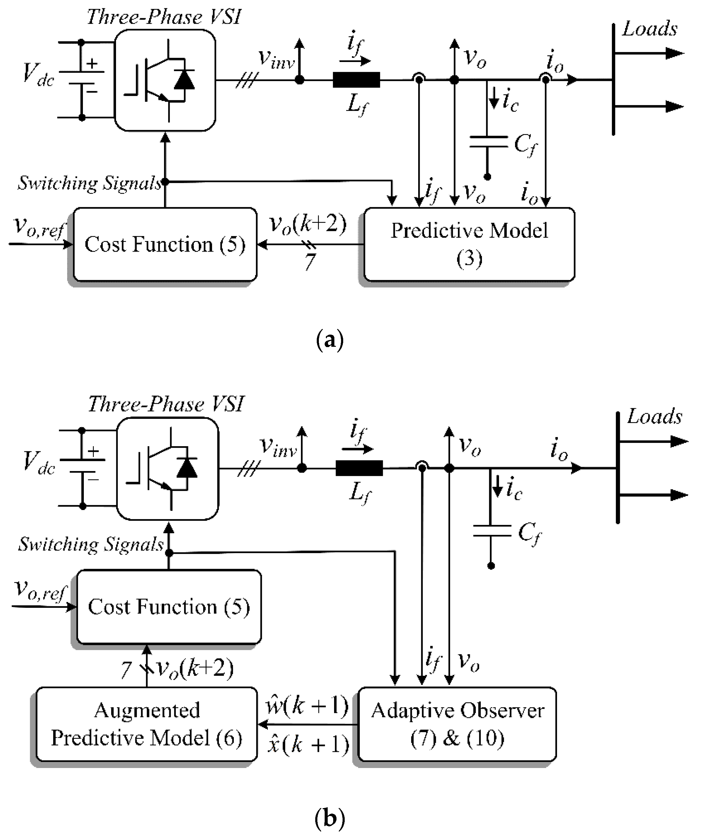
3. Conventional Model Predictive Control (MPC)

In the conventional MPC, Figure 1a, the main goal is selecting the inverter voltage vector that minimizes a cost function. Indeed, the output voltage (vo) is predicted for all possible inverter voltage vectors (vinv) based on the state-space model (3) and measured signals. Then, the inverter voltage vector produces the output voltage with minimum error to the reference one is selected, saved, and applied in the next sampling period. And this procedure is repeated in each sampling period [1,2,11,12,13].
To compensate for one sample control delay, the predicted output voltage at the beginning of the (k+2)th period is required, which is calculated based on the predictive model (3) for different available converter output voltage vectors given as:
v o ( k + 2 ) = A d ( 2 , 1 ) i f ( k + 1 ) + A d ( 2 , 2 ) v o ( k + 1 ) + B d ( 2 , 1 ) v i n v ( k + 1 ) + D d ( 2 , 1 ) i o ( k + 1 )
In the above equation, the sample (k+1) system states are estimated via the state-space model in (3) and measured signals at sample k. Moreover, it is usually assumed that the load-current variations in two consecutive samples are negotiable, i.e., io(k+1) ≈ io (k).
The predicted voltages in (4) are examined in the following cost function, then the optimum voltage vector (vinv) that minimizes the cost function is selected.
{ g = g e v o 2 + λ s w g s w 2 + g i f g e v o = | v o , r e f ( k + 1 ) v o ( k + 2 ) | g s w = | S W ( k + 1 ) S W ( k ) | g i f = { 0         if   | i f ( k ) |     i f , max inf   if   | i f ( k ) |   >   i f , max
As can be seen in (5), the proposed cost function includes different terms. In summary, the main goal of gevo is the minimization of the voltage tracking error. gsw has switching efforts to control switching frequency and switching losses, and finally, gif exposes the inverter (inductor) current constraint. In (5), SW and λsw are gating signals and the constant weighting factor. Weighting factor is usually tuned by trial and error and simulation and experiment to compromise the tracking error and average switching frequency and, consequently, switching losses. However, many efforts have been made to systematically choose weighting factors, as discussed in [31].
The conventional MPC has a simple concept and an appropriate steady-state performance and fast, dynamic response. However, as can be concluded from (4), it depends on the system model’s accuracy. Therefore, uncertainties in the system parameters may degrade the expected system performance or even cause system instability. Moreover, for good disturbance rejection, MPC needs an extra current sensor to measure load currents. Although it provides a simple and good disturbance rejection, it increases the system cost and volume. Also, it decreases the system reliability due to extra components that are subject to damage. To overcome the mentioned issues in the following section, an adaptive MPC is proposed based on the augmented state-space model, which includes all system uncertainties and disturbances. Moreover, a proper adaptive observer is presented to identify this augmented state-space model.

4. Adaptive MPC

As shown in Figure 1b, the proposed control method is based on an augmented model and an adaptive observer to include all model uncertainties and simultaneously eliminate load-current sensors. In the following, the proposed augmented model is presented, and after that, an adaptive observer to estimate model uncertainties and disturbances will be discussed.

4.1. Augmented State-Space Model

The value of parameters Lf and Cf are not precisely known in practice, and they could vary from the nominal amounts. Therefore, system state-space Equation (3) by considering parameters mismatch { A d = A d n + Δ A d B d = B d n + Δ B d D d = D d n + Δ D d and load current as a disturbance input can be written as:
x ( k + 1 ) = A d n x ( k ) + B d n v i n v ( k ) + G d n w ( k ) w = [ w 1 w 2 ] = G d n 1 ( Δ A d x ( k ) + Δ B d u ( k ) + D d i o ( k ) + n ) G d n = [ D d n ( 1 , 1 ) 0 0 D d n ( 2 , 1 ) ] , n = [ n 1 n 2 ]
Also, Δ denotes the deviation from the nominal values, and n1 and n2 represent un-modeled dynamics and system nonlinearities as unstructured uncertainties. It is worth noting that Equation (6) is known as the system’s augmented state-space model, which includes all system uncertainties and disturbances. Moreover, as seen in (6), all system structured (parametric) and unstructured uncertainties are lumped in disturbance input w.

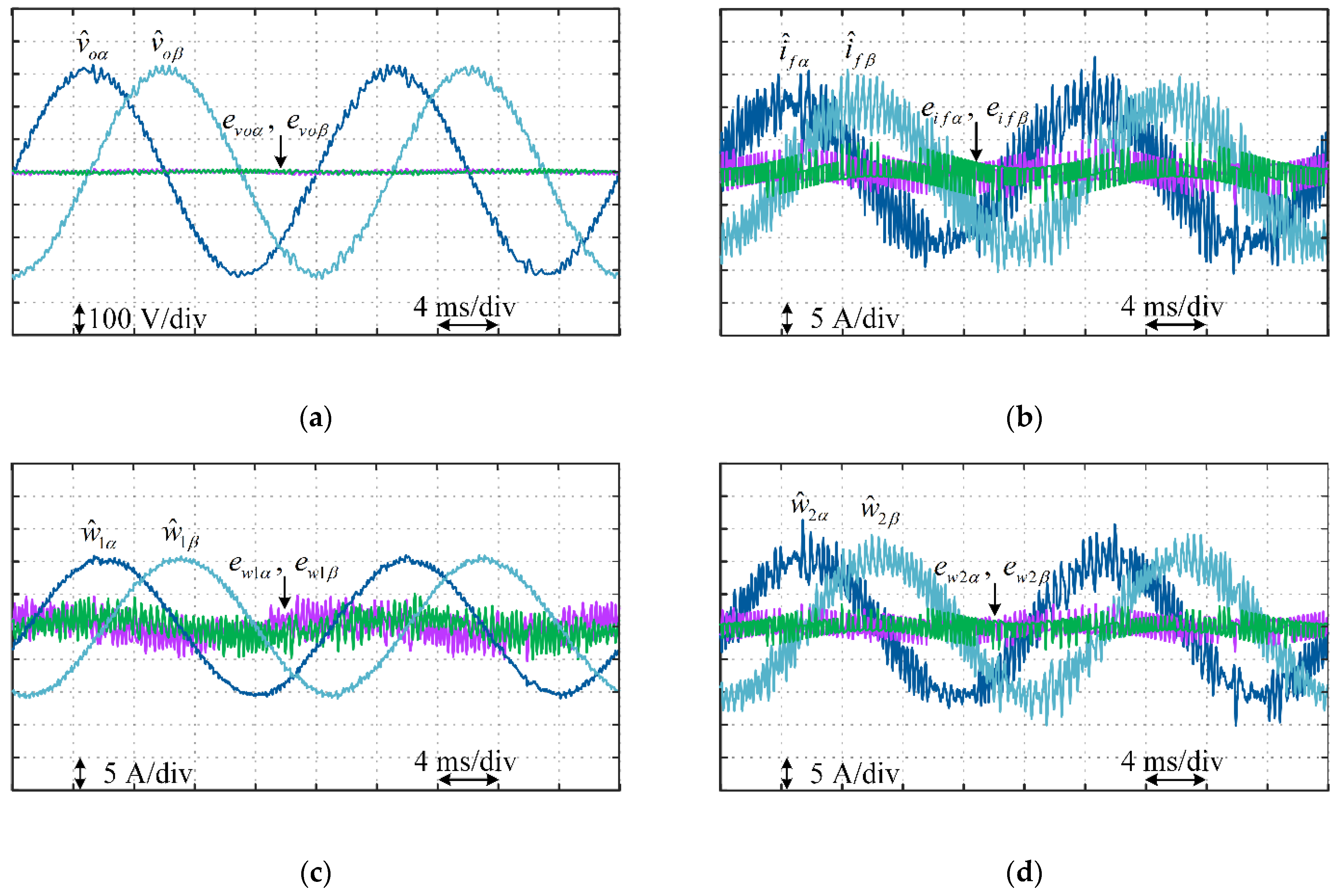
4.2. Adaptive Observer

In this subsection, an adaptive observer is presented to obtain the augmented model and estimate the lumped disturbances (w). The observer also helps the control system to compensate for delays due to digital implementation by estimating signals and disturbances one sample ahead. It also eliminates the load-current sensors, which increases system reliability by removing some physical components subject to damages. Finally, higher noise immunity and size and cost reduction are the other essential advantages of the observer’s determined signals.
An adaptive observer for inverter current dynamic can be constructed as follows:
{ i ^ f ( k + 1 ) = A d n ( 1 , 1 ) i ^ f ( k ) + A d n ( 1 , 2 ) v o ( k ) + B d n ( 1 , 1 ) v i n v ( k ) + D d n ( 1 , 1 ) w ^ 1 ( k ) + G 1 ( i f ( k ) i ^ f ( k ) ) w ^ 1 ( k + 1 ) = w ^ 1 ( k ) + G 2 ( i f ( k ) i ^ f ( k ) )
where, symbol “ˆ” denotes the estimated values, and G1 and G2 are the observer gain. The estimation error dynamics using (6) and (7) are:
{ e i f ( k ) = i f ( k ) i ^ f ( k ) e w 1 ( k ) = w 1 ( k ) w ^ 1 ( k )
Using (6), (7), and (8) and neglecting the disturbance changes in each sampling period (w1(k+1) ≈ w(k)), the error dynamics can be rewritten as:
[ e i f ( k + 1 ) e w 1 ( k + 1 ) ] = [ A d n ( 1 , 1 ) G 1 D d n ( 1 , 1 ) G 2 1 ] A o b 1 [ e i f ( k ) e w 1 ( k ) ]
Therefore, the observer gains must be chosen such that the eigenvalues of the observer (eig(Aob1)) are placed inside the unit circle, which makes the estimation error dynamics of (9) asymptotically stable [12,24].
The same procedure as done for the inductor dynamic observer, can be employed to design the capacitor dynamic observer. The final results are:
{ v ^ o ( k + 1 ) = A d n ( 2 , 1 ) i f ( k ) + A d n ( 2 , 2 ) v ^ o ( k ) + B d n ( 2 , 1 ) v i n v ( k ) + D d n ( 2 , 1 ) w ^ 2 ( k ) + G 3 ( v o ( k ) v ^ o ( k ) ) w ^ 2 ( k + 1 ) = w ^ 2 ( k ) + G 4 ( v o ( k ) v ^ o ( k ) )
Moreover, the observer gains (G3 and G4) can be calculated in such a way the following estimation error dynamic is asymptotically stable, and eigenvalues of the observer (eig(Aob2)) are located inside the unit circle
[ e v o ( k + 1 ) e w 2 ( k + 1 ) ] = [ A d n ( 2 , 2 ) G 3 D d n ( 2 , 1 ) G 4 1 ] A o b 2 [ e v o ( k ) e w 2 ( k ) ]
where the estimation error dynamics are:
{ e v o ( k ) = v o ( k ) v ^ o ( k ) e w 2 ( k ) = w 2 ( k ) w ^ 2 ( k )

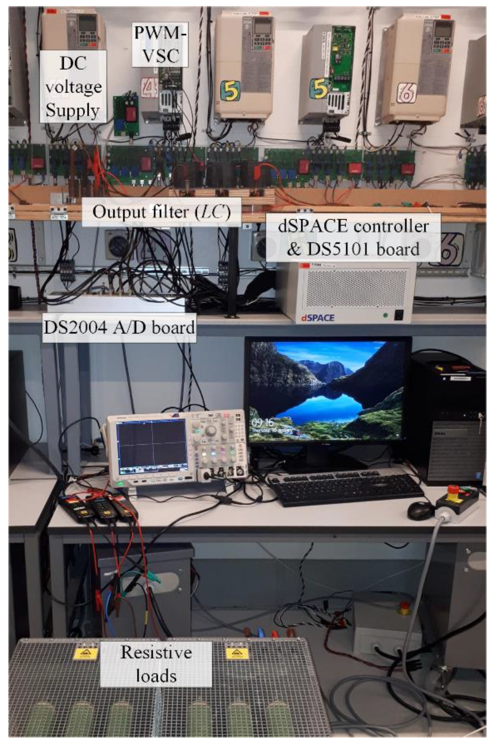
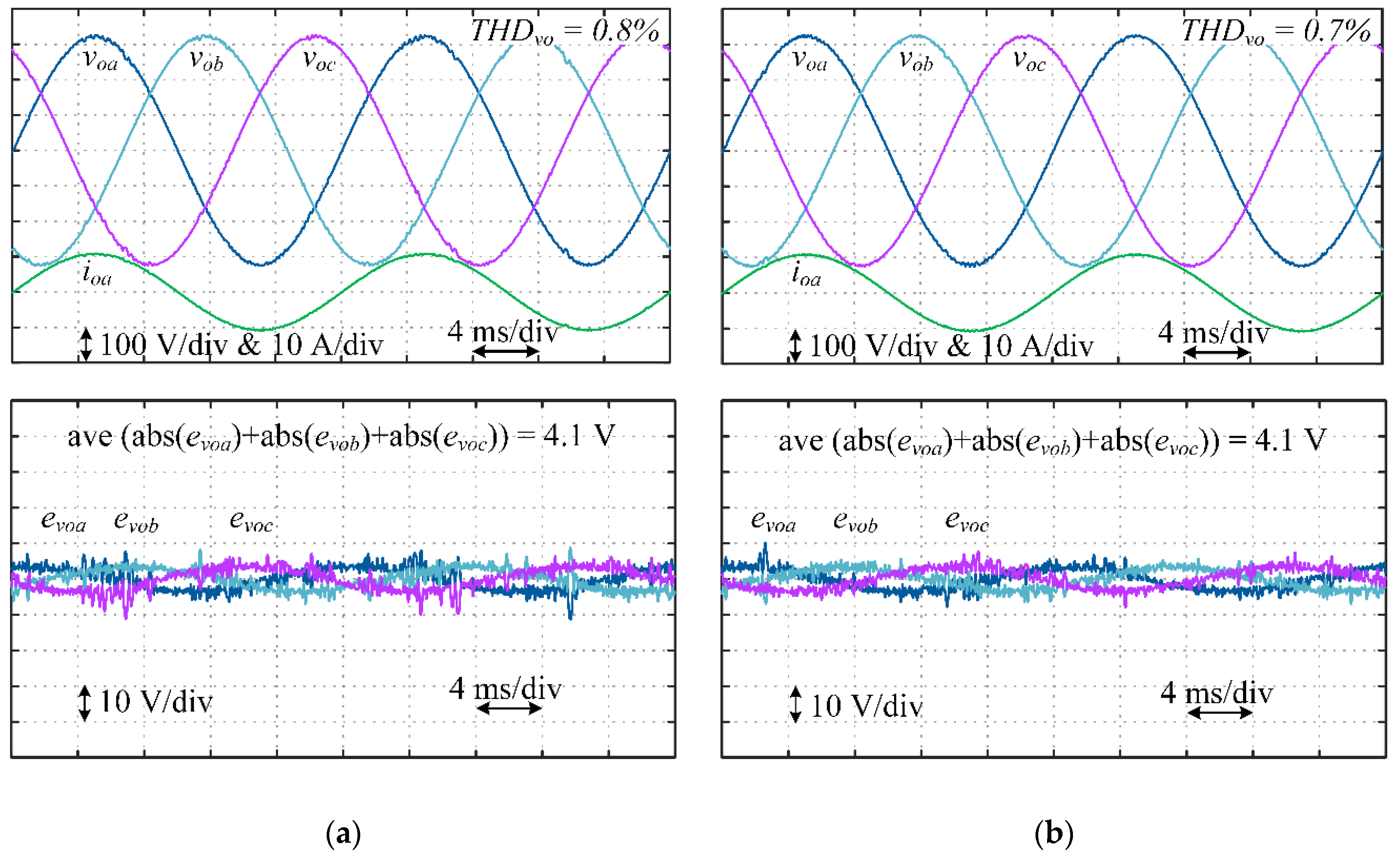
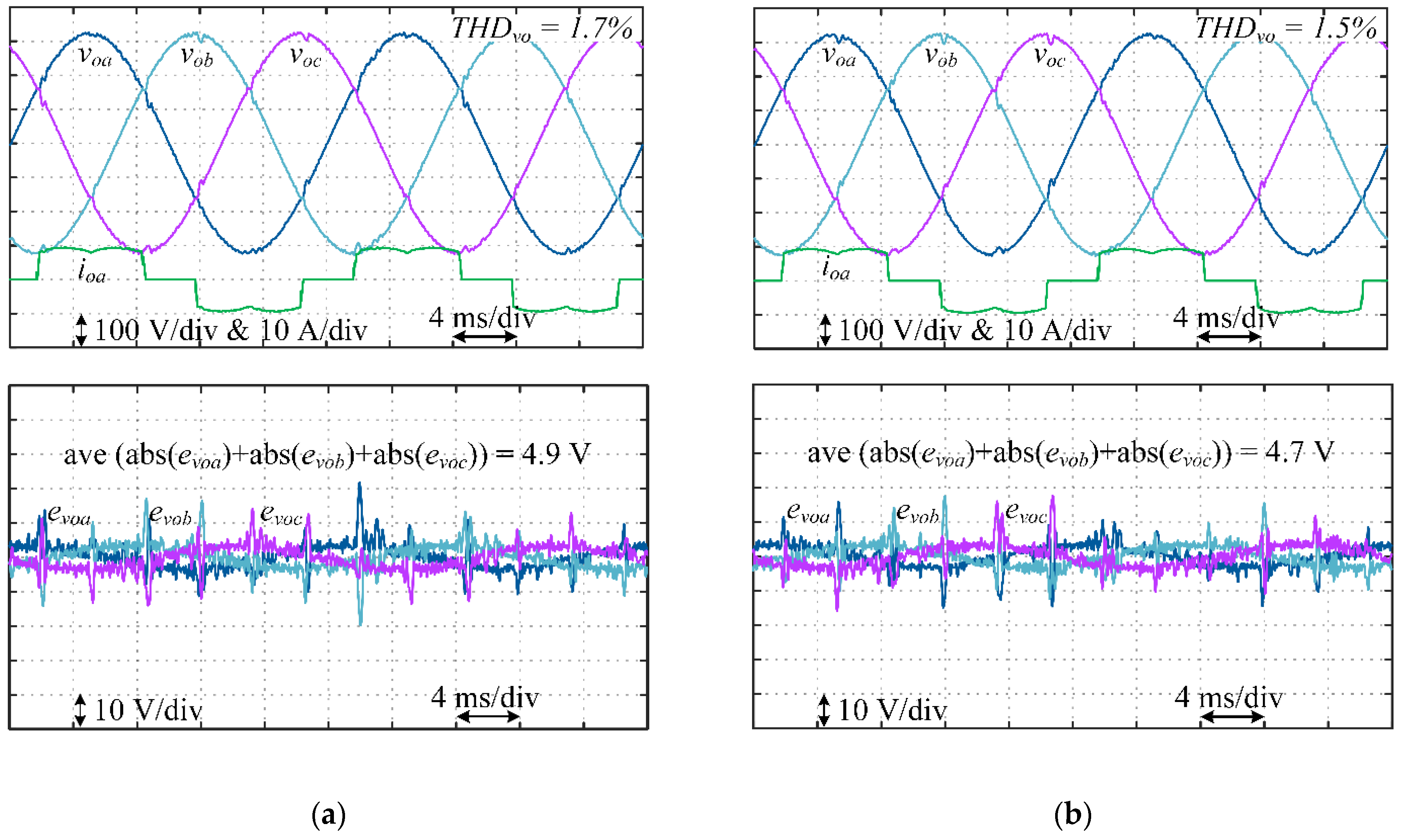
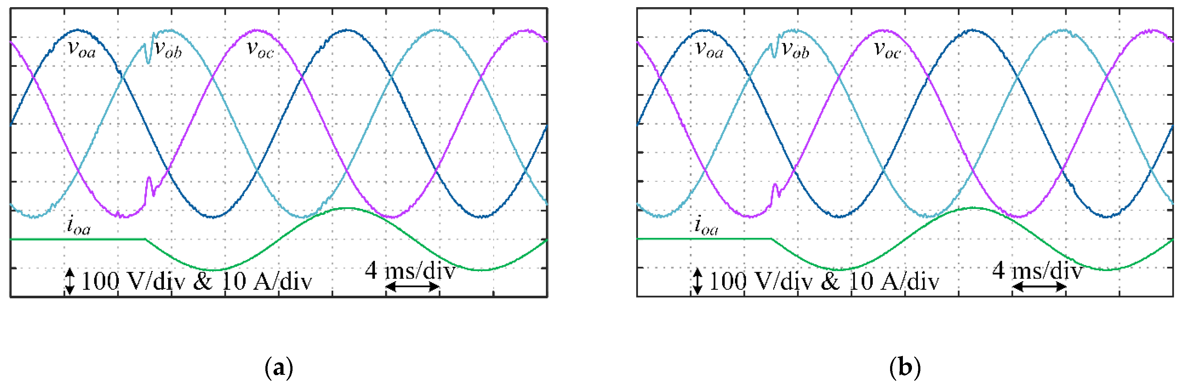
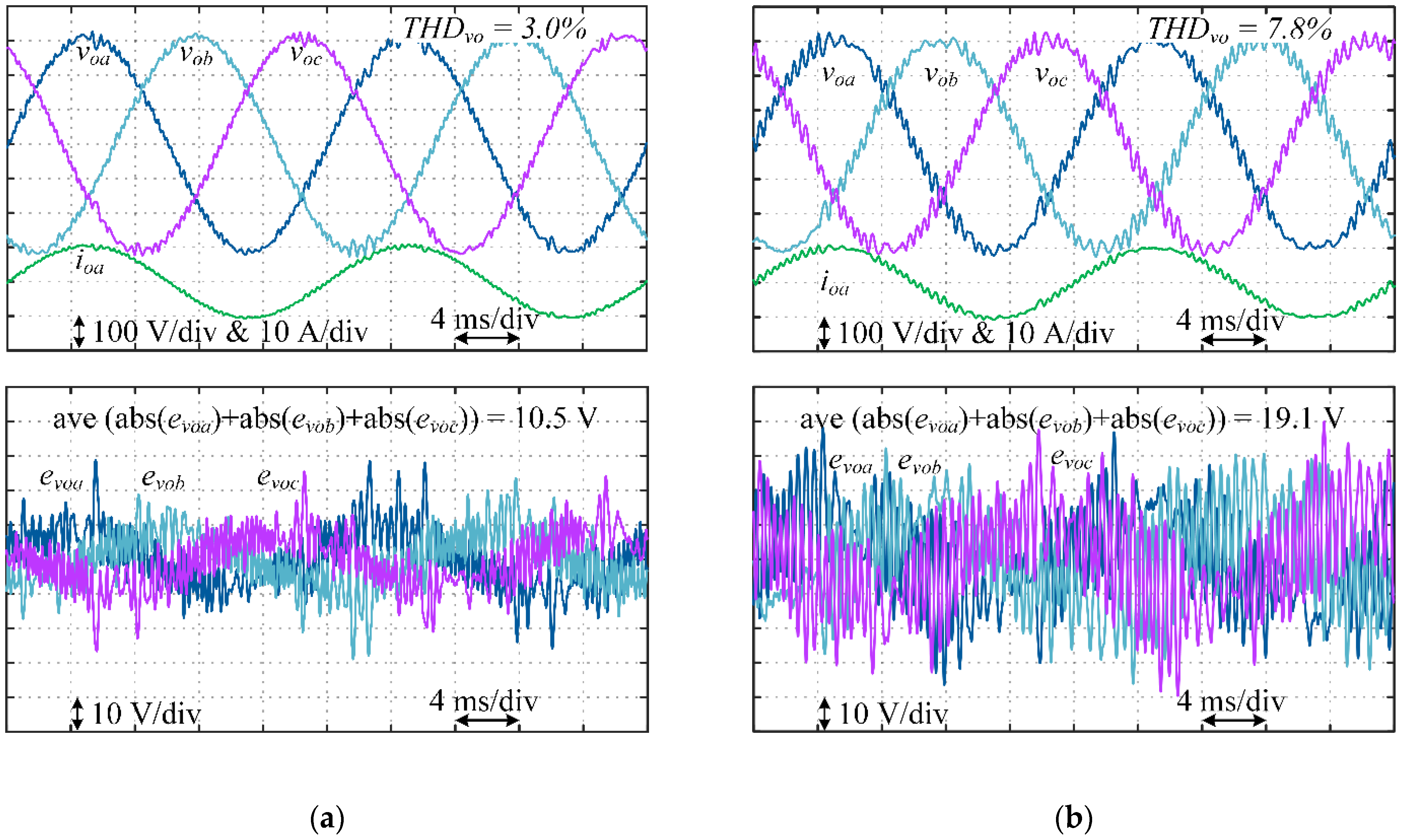
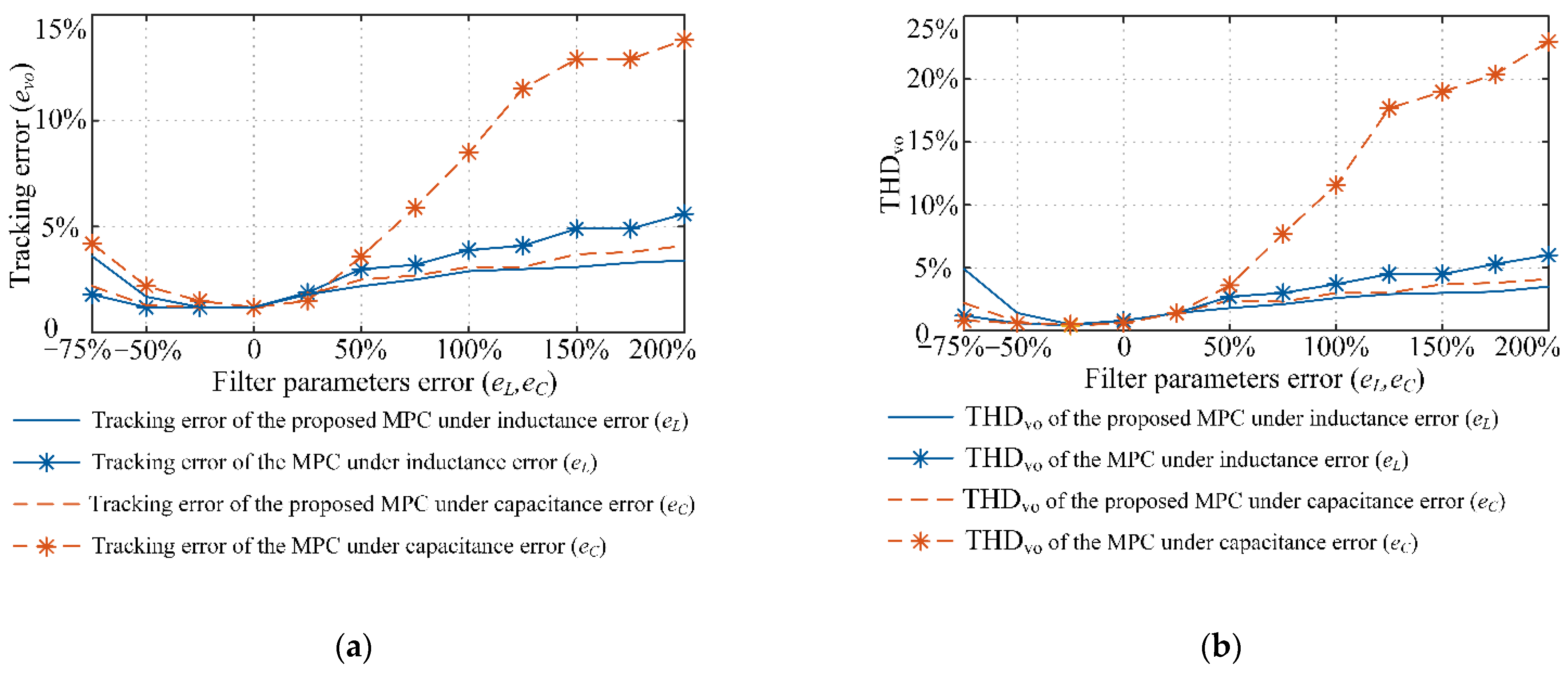
5. Simulation and Experimental Results

The experimental setup in Figure 2 was prepared to check the theoretical analysis. The laboratory setup includes a three-phase 5 kW VSI, a three-phase resistive load, and an LC-type output filter. The DS1007 dSPACE system platform is also employed to drive the VSI and realize both control methods. Moreover, to generate switching pulses and digitalize the measured currents and voltages, a DS5101 digital waveform output board and an Analog-to-Digital DS2004 board are used, respectively. The parameters of three-phase LC-filtered VSI are given in Table 1.
The steady-state performance of the conventional and the proposed adaptive MPC under linear and nonlinear loads are shown in Figure 3 and Figure 4, respectively, which includes output voltages and current and voltage tracking error. Figures confirm the acceptable steady-state error and low total harmonic distortion (THD) of the output voltage under both control methods and different load conditions. It is worth noting that the average switching frequency of the proposed control method and the conventional one under linear (nonlinear) load are 5.7 kHz (5.3 kHz) and 5.8 kHz (5.3 kHz), respectively.
Moreover, the transient performance of both control methods under a step change of resistive load is shown in Figure 5. In this figure, the load power has been suddenly changed from zero to nominal ones. This figure shows excellent transient response and also disturbance rejection using the model predictive control method.
In the previous tests, both control methods have almost the same performance since the filter parameters’ nominal values are used. However, the conventional MPC employs extra load-current sensors, while the proposed MPC only uses the estimated signals provided by the adaptive observer.
The effect of filter parameter uncertainties is investigated in Figure 6, where a 75% error in the filter capacitance is considered as an example. As can be seen, under this condition, the THD of the output voltage under conventional and the proposed MPCs are 7.8% and 3%, respectively. Moreover, the steady-state error under conventional MPC is about twice the proposed ones. Therefore, this parameter uncertainty significantly degrades the performance of the conventional MPC, while the proposed adaptive MPC based on the augmented state-space model and the adaptive observer can adequately tackle this issue. The adaptive observer outputs are shown in Figure 7, including estimated capacitor voltages, inductor currents, lumped disturbances, and estimation errors.
In Figure 8, the performance of the conventional and the proposed control methods in terms of the steady-state error and THD of the output voltage for a wide range of filter parameters uncertainties is investigated, which confirms the excellent robustness of the proposed control method over a wide range of parameters variations. In this figure, eL and eC are errors between the real values of the filter inductance and capacitance and the estimated ones in the control system:
e L = ( L c L f L f ) × 100 ,   e C = ( C c C f C f ) × 100
L and C are the filter inductance and capacitance, and subscripts f and c denote the output filter and control system parameters.
Finally, to evaluate the testability of the proposed control method in practice, many tests have been carried out in the laboratory setup. Performance of the proposed adaptive MPC under different conditions, including steady-state operation under linear and nonlinear loads, and transient performance and load-current disturbance rejection are shown in Figure 9. The experimental results are the same as the simulated ones and confirm the proposed method’s excellent performance in practice.
In the end, it is worth noting that the proposed adaptive MPC improves system robustness and provides load-current-sensorless operation, however at the same time, it does not increase the complexity and computations of the conventional one considerably. Indeed, the conventional MPC employs the state-space model in (3) and measured signals to compensate for the control delay. In contrast, the proposed adaptive MPC replaces the open-loop estimator (3) with the closed-loop ones in (7) and (10). Therefore, as can be seen from (3), (7), and (10), the proposed estimator has eight more sums and four multiplications, which is negligible regarding the total calculations and existence of powerful processors. However, these extra computations remarkably increase the system performance and provide the proposed control method’s sensorless operation, which increases the system reliability, and reduces the cost and size.

6. Conclusions

An adaptive MPC based on the augmented state-space model and the adaptive observer in a three-phase LC-filtered VSI has been proposed in this work. Unlike the conventional ones, all system uncertainties and disturbances are considered and estimated by the adaptive observer in the proposed control method. The adaptive observer can also provide the load-current-sensorless operation, which reduces size and cost and simultaneously improves the system reliability. Moreover, extensive simulations and experiments have examined both control methods’ performance under different load conditions and uncertain parameters. Results confirm significant advantages of the proposed adaptive MPC over the conventional one regarding the steady-state error and THD of the output voltage.

Author Contributions

Conceptualization, H.G.-K., P.D., and F.B.; methodology, H.G.-K.; software, H.G.-K.; validation, H.G.-K.; formal analysis, H.G.-K. and P.D.; investigation, H.G.-K., P.D. and F.B.; resources, P.D. and F.B.; data curation, H.G.-K.; writing—original draft preparation, H.G.-K.; writing—review and editing, H.G.-K., P.D., and F.B.; visualization, H.G.-K.; supervision, F.B. and P.D.; project administration, H.G.-K.; funding acquisition, F.B. and P.D.; All authors have read and agreed to the published version of the manuscript.

Funding

The work is supported by the Reliable Power Electronic-Based Power System (REPEPS) project at the Department of Energy Technology, Aalborg University as a part of the Villum Investigator Program funded by the Villum Foundation.

Institutional Review Board Statement

Not applicable.

Informed Consent Statement

Not applicable.

Data Availability Statement

Data available in a publicly accessible repository.

Conflicts of Interest

The authors declare no conflict of interest.

Nomenclature

VSIVoltage source inverter
LCInductor and capacitor filter
PIProportional-integral
PRProportional-resonant
MPCModel predictive control
SMCSliding mode control
HCHarmonic compensator
IACIndirect adaptive control
DACDirect adaptive control
PWMPulse-width modulation
THDTotal harmonic distortion

References

  1. Zheng, C.; Dragicevic, T.; Blaabjerg, F. Current-Sensorless Finite-Set Model Predictive Control for LC-Filtered Voltage Source Inverters. IEEE Trans. Power Electron. 2019, 35, 1086–1095. [Google Scholar] [CrossRef]
  2. Heydari, R.; Dragicevic, T.; Blaabjerg, F. High-Bandwidth Secondary Voltage and Frequency Control of VSC-Based AC Microgrid. IEEE Trans. Power Electron. 2019, 34, 11320–11331. [Google Scholar] [CrossRef] [Green Version]
  3. Alhasheem, M.; Blaabjerg, F.; Mattavelli, P.; Davari, P. Model Predictive Control of Grid Forming Converters with Enhanced Power Quality. Appl. Sci. 2020, 10, 6390. [Google Scholar] [CrossRef]
  4. He, J.; Chok, Y.C.; Zhang, X.; Li, Z.; Liu, Z. An Adaptive Dual-Loop Lyapunov-Based Control Scheme for a Single-Phase UPS Inverter. IEEE Trans. Power Electron. 2020, 35, 8886–8891. [Google Scholar] [CrossRef]
  5. Zou, Z.X.; Buticchi, G.; Liserre, M. Grid Identification and Adaptive Voltage Control in a Smart Transformer-Fed Grid. IEEE Trans. Power Electron. 2019, 34, 2327–2338. [Google Scholar] [CrossRef]
  6. Liao, Y.; Wang, X.; Blaabjerg, F. Passivity-Based Analysis and Design of Linear Voltage Controllers for Voltage-Source Converters. IEEE Open J. Ind. Electron. Soc. 2020, 1, 114–126. [Google Scholar] [CrossRef]
  7. Han, Y.; Fang, X.; Yang, P.; Wang, C.; Xu, L.; Guerrero, J.M. Stability Analysis of Digital-Controlled Single-Phase Inverter with Synchronous Reference Frame Voltage Control. IEEE Trans. Power Electron. 2018, 33, 6333–6350. [Google Scholar] [CrossRef] [Green Version]
  8. De Bosio, F.; De Souza Ribeiro, L.A.; Freijedo, F.D.; Pastorelli, M.; Guerrero, J.M. Effect of State Feedback Coupling and System Delays on the Transient Performance of Stand-Alone VSI with LC Output Filter. IEEE Trans. Ind. Electron. 2016, 63, 4909–4918. [Google Scholar] [CrossRef] [Green Version]
  9. Loh, P.C.; Holmes, D.G. Analysis of Multiloop Control Strategies for LC/CL/LCL-Filtered Voltage-Source and Current-Source Inverters. IEEE Trans. Ind. Appl. 2005, 41, 644–654. [Google Scholar] [CrossRef]
  10. Loh, P.C.; Newman, M.J.; Zmood, D.N.; Holmes, D.G. A Comparative Analysis of Multiloop Voltage Regulation Strategies for Single and Three-Phase UPS Systems. IEEE Trans. Power Electron. 2003, 18, 1176–1185. [Google Scholar]
  11. Cortes, P.; Ortiz, G.; Yuz, J.I.; Rodriguez, J.; Vazquez, S.; Franquelo, L.G. Model Predictive Control of an Inverter with Output LC Filter for UPS Applications. IEEE Trans. Ind. Electron. 2009, 56, 1875–1883. [Google Scholar] [CrossRef]
  12. Gholami-Khesht, H.; Davari, P.; Blaabjerg, F. Adaptive Predictive-DPC for LCL-Filtered Grid Connected VSC with Reduced Number of Sensors. In Proceedings of the 2020 22nd European Conference on Power Electronics and Applications (EPE’20 ECCE Europe), Lyon, France, 7–11 September 2020. [Google Scholar]
  13. Bozorgi, A.M.; Gholami-Khesht, H.; Farasat, M.; Mehraeen, S.; Monfared, M. Model Predictive Direct Power Control of Three-Phase Grid-Connected Converters with Fuzzy-Based Duty Cycle Modulation. IEEE Trans. Ind. Appl. 2018, 54, 4875–4885. [Google Scholar] [CrossRef]
  14. Pilloni, A.; Pisano, A.; Usai, E. Robust Finite-Time Frequency and Voltage Restoration of Inverter-Based Microgrids via Sliding-Mode Cooperative Control. IEEE Trans. Ind. Electron. 2018, 65, 907–917. [Google Scholar] [CrossRef]
  15. Komurcugil, H. Rotating-Sliding-Line-Based Sliding-Mode Control for Single-Phase UPS Inverters. IEEE Trans. Ind. Electron. 2012, 59, 3719–3726. [Google Scholar] [CrossRef]
  16. Celani, F.; Macellari, M.; Schirone, L. Discrete-Time Control for DC–AC Converters Based on Sliding Mode Design. IET Power Electron. 2012, 5, 833–840. [Google Scholar]
  17. Kukrer, O.; Komurcugil, H.; Doganalp, A. A Three-Level Hysteresis Function Approach to the Sliding-Mode Control of Single-Phase UPS Inverters. IEEE Trans. Ind. Electron. 2009, 56, 3477–3486. [Google Scholar] [CrossRef]
  18. Gholami-Khesht, H.; Monfared, M. Adaptive Predictive Voltage Control of Three-Phase PWM-VSCs in UPS Applications. In Proceedings of the 2016 International Siberian Conference on Control and Communications (SIBCON), Moscow, Russia, 12–14 May 2016; pp. 1–6. [Google Scholar]
  19. Kim, J.; Choi, H.h.; Jung, J.-W. MRAC-Based Voltage Controller for Three-Phase CVCF Inverters to Attenuate Parameter Uncertainties Under Critical Load Conditions. IEEE Trans. Power Electron. 2020, 35, 1002–1013. [Google Scholar] [CrossRef]
  20. Do, T.D.; Leu, V.Q.; Choi, Y.S.; Choi, H.H.; Jung, J.W. An Adaptive Voltage Control Strategy of Three-Phase Inverter for Stand-Alone Distributed Generation Systems. IEEE Trans. Ind. Electron. 2013, 60, 5660–5672. [Google Scholar] [CrossRef]
  21. Alhasheem, M.; Mattavelli, P.; Davari, P. Harmonics Mitigation and Non-ideal Voltage Compensation Utilising Active Power Filter based on Predictive Current Control. IET Power Electron. 2020, 13, 2782–2793. [Google Scholar] [CrossRef]
  22. Davari, P.; Yang, Y.; Zare, F.; Blaabjerg, F. Predictive Pulse-Pattern Current Modulation Scheme for Harmonic Reduction in Three-Phase Multidrive Systems. IEEE Trans. Ind. Electron. 2016, 63, 5932–5942. [Google Scholar] [CrossRef] [Green Version]
  23. Bozorgi, A.M.; Gholami-Khesht, H.; Farasat, M.; Mehraeen, S.; Monfared, M. Voltage Sensorless Improved Model Predictive Direct power Control for Three-Phase Grid-Connected Converters. In Proceedings of the 2017 IEEE Energy Conversion Congress and Exposition (ECCE), Cincinnati, OH, USA, 1–5 October 2017; pp. 4957–4963. [Google Scholar]
  24. Gholami-Khesht, H.; Monfared, M. Deadbeat Direct Power Control for Grid Connected Inverters Using a Full-Order Observer. In Proceedings of the 2015 4th International Conference on Electric Power and Energy Conversion Systems (EPECS), Sharjah, UAE, 24–26 November 2015; pp. 6–10. [Google Scholar]
  25. Lascu, C.; Argeseanu, A.; Blaabjerg, F. Supertwisting Sliding-Mode Direct Torque and Flux Control of Induction Machine Drives. IEEE Trans. Power Electron. 2020, 35, 5057–5065. [Google Scholar] [CrossRef]
  26. Vieira, R.P.; Martins, L.T.; Massing, J.R.; Stefanello, M. Sliding Mode Controller in a Multiloop Framework for a Grid-Connected VSI With LCL Filter. IEEE Trans. Ind. Electron. 2018, 65, 4714–4723. [Google Scholar] [CrossRef]
  27. Guzman, R.; de Vicuna, L.G.; Castilla, M.; Miret, J.; Martin, H. Variable Structure Control in Natural Frame for Three-Phase Grid-Connected Inverters With LCL Filter. IEEE Trans. Power Electron. 2018, 33, 4512–4522. [Google Scholar] [CrossRef]
  28. Astrom, K.J.; Wittenmark, B. Adaptive Control, 2nd ed; Addison-Wesley: New York, USA, 1995. [Google Scholar]
  29. Abdel-Rady, I.M.Y.; El-Saadany, E.F. Adaptive Discrete-Time Grid-Voltage Sensorless Interfacing Scheme for Grid-Connected DG-Inverters Based on Neural-Network Identification and Deadbeat Current Regulation. IEEE Trans. Power Electron. 2008, 23, 308–321. [Google Scholar]
  30. Abdel-Rady, I.M.Y.; El-Saadany, E.F. An Improved Deadbeat Current Control Scheme With A Novel Adaptive Self-Tuning Load Model for a Three-Phase PWM Voltage-Source Inverter. IEEE Trans. Ind. Electron. 2007, 54, 747–759. [Google Scholar] [CrossRef]
  31. Karamanakos, P.; Geyer, T. Guidelines for the Design of Finite Control Set Model Predictive Controllers. IEEE Trans. Power Electron. 2020, 35, 7434–7450. [Google Scholar] [CrossRef]
Figure 1. Single-phase diagram of three-phase LC-filtered voltage source inverter (VSI) under (a) conventional model predictive control (MPC), (b) proposed adaptive MPC.
Applsci 11 00704 g001
Figure 2. Experimental setup to implement the conventional model predictive control (MPC) and the proposed adaptive MPC on a three-phase inductor and capacitor filter (LC)-filtered voltage source inverter (VSI).
Applsci 11 00704 g002
Figure 3. Simulation results showing steady-state performance under nominal linear load (5 kW), (a) the proposed adaptive MPC, (b) conventional MPC.
Applsci 11 00704 g003
Figure 4. Simulation results showing steady-state performance under nominal nonlinear load (5 kW), (a) the proposed adaptive MPC, (b) conventional MPC.
Applsci 11 00704 g004
Figure 5. Simulation results showing transient performance under step-change of the load from zero to 5 kW of the VSI, (a) the proposed adaptive MPC, (b) conventional MPC.
Applsci 11 00704 g005
Figure 6. Simulation results showing steady-state performance under nominal load (5 kW) and 75% error in the initial value of filter capacitance (eC = 75%), (a) the proposed adaptive MPC, (b) conventional MPC.
Applsci 11 00704 g006
Figure 7. Simulation results showing outputs of the proposed adaptive observer under nominal load (5 kW) and 75% error in the initial value of filter capacitance (eC = 75%), (a) estimated capacitor voltages and voltage estimation errors (b) estimated inverter currents and current estimation errors, (c,d) estimated disturbance inputs and disturbance estimation errors.
Applsci 11 00704 g007
Figure 8. Simulation results showing robustness analysis of the proposed adaptive MPC and conventional MPC against the filter parameters uncertainties, (a) voltage tracking error, (b) total harmonic distortion (THDvo).
Applsci 11 00704 g008
Figure 9. Experimental results showing performance of the proposed adaptive MPC under different conditions, (a) and (b) steady-state performance under linear and nonlinear loads, and (c) transient performance under step-change of the load from zero to 5 kW.
Applsci 11 00704 g009
Table 1. System parameters.
Voltage Source Inverter(VSI) and Inductor and Capacitor (LC) Filter
Nominal power5 (kW)
Line voltage (rms)400 (V)
Output frequency (f)50 (Hz)
Inductor (Lf)4 (mH)
Capacitor (Cf)20 (µF)
DC-link voltage (Vdc)700 (V)
Sampling time (TS)25 (µs)
Linear Load
Three-phase resistive load30 (Ω)
Nonlinear Load
Three-phase diode-bridge rectifier
Resistive load60 (Ω)
Control Parameters
λSW0.5
Observer Poles0.03, 0.05, 0.35, 0.95
Publisher’s Note: MDPI stays neutral with regard to jurisdictional claims in published maps and institutional affiliations.

