1. Introduction
The use of clasp-retained removable partial dentures has been a popular option among patients and clinicians to rehabilitate patients with partial edentulism due to the non-invasive nature of the treatment and fair cost-efficiency relationship on the short-term [
1,
2]. However, on the long-term, this cost-efficiency relationship is disturbed by the limitations of a removable partial denture, which inevitably leads to patient dissatisfaction and a drop of the usage rate, particularly, in the case of mandibular distal extension dentures [
3,
4,
5].
To reduce some of these limitations, the adjunctive use of dental implants with or without retentive elements have been proposed by several authors [
6,
7,
8,
9,
10] and are called implant-assisted removable partial dentures. The typical indications for implant-assisted removable partial dentures are situations of Kennedy Class I and II edentulism, particularly with long edentulous spans, and Kennedy class IV situations, or situations of patient refusal to wear dentures with complete palatal coverage or visible clasp assemblies and insufficient retention in the existing removable partial dentures. In these cases, the type of implant to use and the position within the edentulous sites, as well as the type of retentive elements, is a decision of the clinician, often based on surgical, aesthetic or economic criteria [
11].
The clinical guidelines and principles for the design of implant-assisted removable partial dentures proposed by Grossmann et al. [
12] in patient situations of Kennedy Class I edentulism indicate that per edentulous area, one implant should be inserted as distally as possible to provide maximal support and stability, particularly in the mandible. However, they also admit the possibility of placing the implants in a mesial position adjacent to the abutment teeth (natural teeth supporting and retaining a removable partial denture), whenever these are poor to provide support or to avoid unesthetic clasps in maxillary rehabilitations. Only two non-clinical studies considered in the work of Grossmann et al. comprised the biomechanical evaluation of the use of dental implants in mandibular Kennedy Class I situations, that is the study of movement and deformation of the biological structures (abutment teeth, bone, mucosa, etc.) under forces applied over the prosthesis and implants. One of those studies, performed by Ohkubo et al. [
13], used an experimental setup to measure the pressure under a conventional or an implant-assisted removable partial denture with the implants placed distally. The results indicated that the implant support contributed to the reduction of displacement at the distal extension of the removable partial dentures and decreased the pressure on soft tissues. The other study [
14] also considered in the above-mentioned revision, evaluated the biomechanical efficacy of placing implants underneath the denture base to obtain stable occlusal support, using an in-silico bi-dimensional model. The authors considered the possibility of implant support in the distal (second molar), mesial (first premolar) or intermediate position (second premolar). Compared to the conventional removable partial denture option, the least stress was obtained at the temporomandibular joint using the implant in the distal position, followed by the intermediate and mesial positions.
The study of Maeda et al. was the first to use the finite element method (FEM) to evaluate the biomechanical effect of the implant support in the structures involved, namely denture, mandibular bone and temporomandibular joint. In the time following that study, several researchers have been using the finite element method to evaluate the stress distribution over the mandibular bone due to the screwed overdenture positioned on dental implants [
15,
16,
17,
18,
19,
20]. In this study, three-dimensional finite element analysis is also used to clarify the criteria for implant positioning within the edentulous span in prosthetic treatments with IARPD (implant assisted removable partial dentures). The primary aim is achieved by evaluating the different patterns of stress in the prosthetic structure for variations of the implant positioning in the edentulous area.
2. Materials and Methods
2.1. Geometrical Models
Three-dimensional finite element models of IARPDs with two different implant locations and one conventional RPD, that is, a tooth assisted RPD, were constructed based on the reconstruction of the CBCT Kennedy Class I patient. The three finite element models were identified as: the conventional RPD; the IARPD PREMOLARS (IARPD PM), presenting the implants at the premolar regions; the IARPD MOLARS (IARPD MO), with the implants placed in the molar’s region. The selected patient showed no signs of relevant systemic or oral diseases, including severe periodontal disease, and presented mandibular bilateral posterior edentulism missing three teeth per edentulous site and moderate resorption of the residual ridges.
The geometries of the compact and trabecular bones of the mandible were created by the conversion of the CBCT scan raw medical data into 3D models and subsequent conversion to a CAD file by reverse engineering methods. Similarly, to the process of segmentation of the mandible bones, teeth segmentation allowed separating abutment teeth (34, 33, 43, 44) from the remaining teeth, while periodontal ligaments were modelled by offsetting the mesh of the root surface of each tooth (34, 33, 43, 44) by 0.25 to 0.3 mm. The 3D geometrical model of the acrylic portion of the RPD was obtained from the scanning of a conventional denture, which had been created over the plaster mode of the patient, using the inEOS® X5 laboratory scanner (Sirona Dental Systems Inc., Long Island City, NY, USA). The 3D model of the metal framework of the RPD was created over the scanned plaster model using the 3Shape Dental System™ software and, posteriorly, assembled with the acrylics of the 3rd and 4th quadrants. Moreover, the external surface of the mandibular plaster model of the patient was also scanned to create a 3D model of the coronal portion of the remaining teeth and soft tissue of the edentulous areas.
The implants were created using s CAD tools (Solidworks® 2014, Dassault Systèmes Pte. Ltd., Singapore) after feature extraction of the specific geometrical dimensions from official images of Straumann Standard Plus implants (Ø 4.1 mm) with regular platform and 10 mm long provided by the manufacturer (Institut Straumann AG, Basel, Switzerland). A ball attachment (patrix) and corresponding matrix were also created to establish the connection between prosthesis and the implant. In the assemblage of IARPD models the implants were placed as parallel as possible to the abutment teeth in the regions of the second premolar (Model IARPD PM) and of the extremity of metallic framework (Model IARPD MO), which corresponded to the virtual position of the first molar. To model the implant-bone contact, the implants were then trimmed from the cortical and cancellous bone bodies using Boolean operations. The same operation was performed on the soft tissue body to create the space required to the transmucosal portion of the implant. The matrices were aligned with the ball attachments of the implants and housed within the framework. The acrylic portions of the prostheses were also modified to accommodate the implants, ball attachments and matrices.
A single plate was created to apply the prescribed load uniformly over the acrylic teeth of the removable partial denture. The plate was sketched in the horizontal plane of the mandible (parallel to the occlusal plane) and vertically extruded to obtain a final thickness of 10 mm. Additionally, a 10 mm diameter circle was included in the geometric centre of the sketch and extruded 25 mm for force application. After the assembly of all components of the models with implant-assisted removable partial dentures, the solid bodies were exported in the format of single Parasolid binary files.
2.2. Numerical Models
Each one of the three model files was imported into the ADINA system for linear and nonlinear finite element analysis (ADINA AUI version 9.3.1, ADINA R&D Inc., Watertown, WA, USA) including the following bodies: cortical bone and non-abutment teeth; individualized abutment teeth (34, 33, 43, 44); individualized periodontal ligaments of the abutment teeth (34, 33, 43, 44); cancellous bone; soft tissue (3rd and 4th quadrants); metal framework of the removable partial denture (including 2 matrices in the case of the Models IARPD PM and IARPD MO); acrylic denture bases with the missing teeth (3rd and 4th quadrants); implants and ball attachments (Models IARPD PM and IARPD MO); loading plate.
In both numerical models of the IARPDs the implants were assumed bonded with cancellous and cortical bones, simulating complete osseointegration. Moreover, the glue mesh option was also used to model the attachment of other pairs of components to remain perfectly bonded together, such as the inner surfaces of the cortical bone and the outer surfaces of the cancellous bone or the inner and outer surfaces of the periodontal ligament and the teeth and bone, respectively. Nevertheless, the Lagrange multiplier technique was used to impose contact constraint conditions, assuring the possibility of relative motion between the surfaces of the following contact pairs: implant/soft-tissue; soft-tissue/acrylic; soft-tissue/framework; framework/teeth; teeth-premolar/teeth-canine; teeth/cortical; and acrylic/implant.
Assignment of the mesh density to the solid bodies of each model was made by promoting equally spaced subdivisions of the bodies using the desired element edge length. In some cases, the subdivision of specific faces was recalculated with smaller lengths to promote a more refined mesh in areas requiring higher precision of the results.
Table 1 presents the mesh density attributed to each body and the refinement areas. Discretization of the domains was assured by the Delaunay free-form meshing algorithm to generate 8-node hexahedral (brick) elements with mixed interpolation formulation (displacement and pressure-based), considering a constant pressure (1 degree of freedom). For elements with linear elastic material properties, additional displacement degrees of freedom were allowed by selecting the incompatible modes option. The total number of nodes and elements of each model are detailed in
Table 2.
2.3. Numerical Models
This study assumed isotropic linear elastic properties for the cortical and cancellous bones, teeth, framework, acrylic, implants, ball attachments and loading plate but not for the oral soft tissues. These, i.e., oral mucosa and periodontal ligament, were modelled considering non-linear hyperelastic properties. Several models have been proposed to model the hyperelastic effects of biological soft tissues [
21]. Nevertheless, the approximation proposed by Ogden [
22,
23] provides the closest matching to experimental data and was herein considered for the modelling of both the oral mucosa and the periodontal ligament. The mechanical properties of the materials displaying a linear force-displacement relationship as implied in Hooke’s law are presented in
Table 3.
The nonlinear constitutive models of the oral mucosa and of periodontal ligaments were derived from a strain energy density function (SEDF), W, which is defined per unit of reference volume (ADINA R&D 2012). This model is based directly on principal stretches instead of invariants to determine the deviatoric strain energy function (WD) and accounts for volumetric compressibility by the inclusion of a term for the volumetric strain energy density (ADINA R&D 2012). In the case of the oral mucosa, the strain energy density function was set based on the fitting of a uniaxial stress–strain curve from experimental data reported by Kishi et al. in 1972 cited in Chen et al. [
30], using a Ogden 9th order approximation obtained by the method of singular value decomposition. Similarly, the periodontal ligament material properties were obtained from the data of porcine periodontal ligaments subjected to uniaxial tensile tests that were performed along the fibber direction, as reported by Natali et al. [
31] and Nishihira et al. [
32]. The curve fitting procedure for the Ogden function was also obtained by singular value decomposition and 9th order approximation.
2.4. Loading and Boundary Conditions
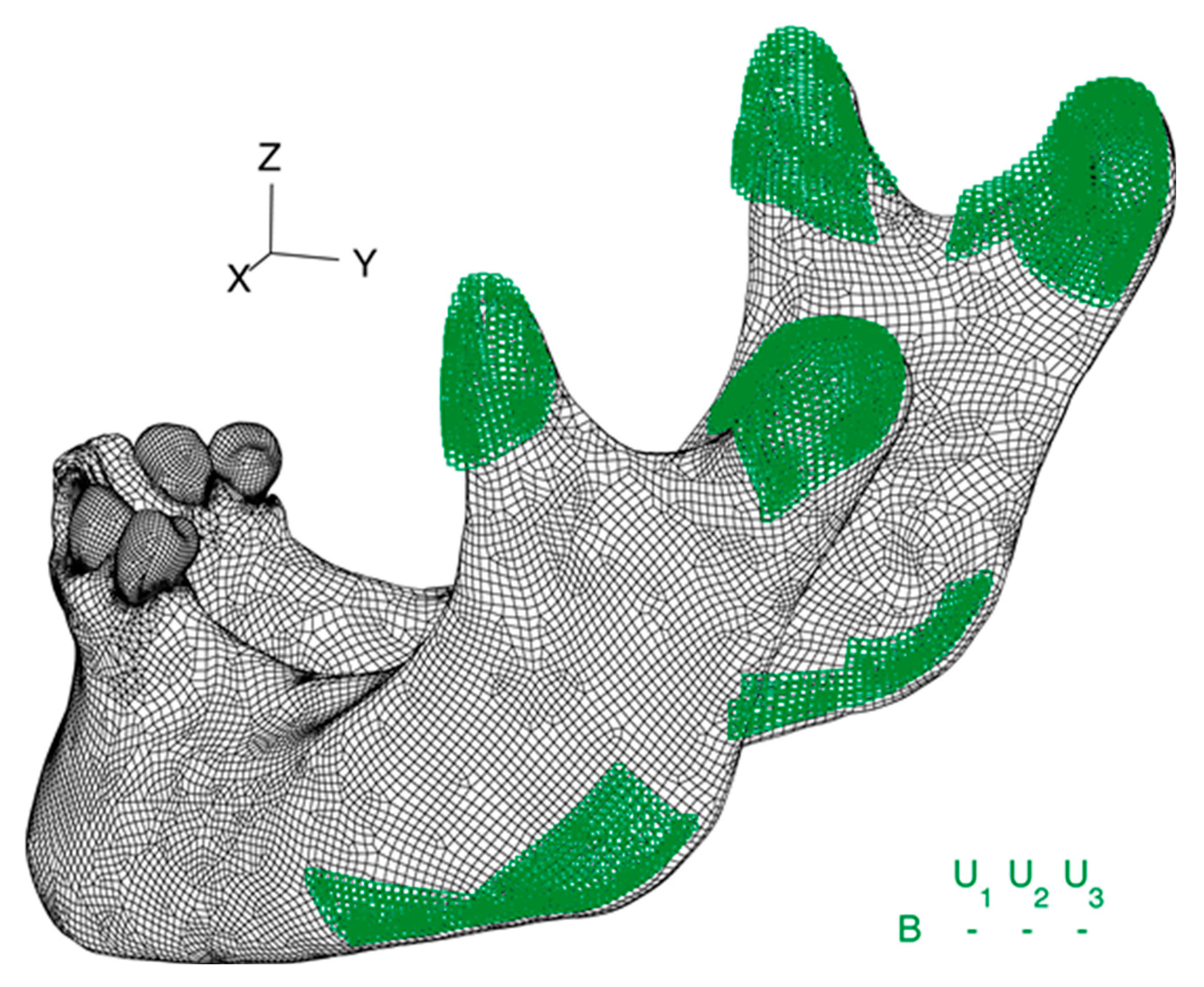
Boundary conditions were applied in the condyles of the mandible and in the insertion areas of the mastication muscles. Thus, as shown in
Figure 1, all three nodal degrees of freedom were fixed in the insertion of the masseter muscle in the lower border of the mandible and in the insertion of the medial pterygoid, the middle temporalis, and the lateral pterygoid muscles in the coronoid process.
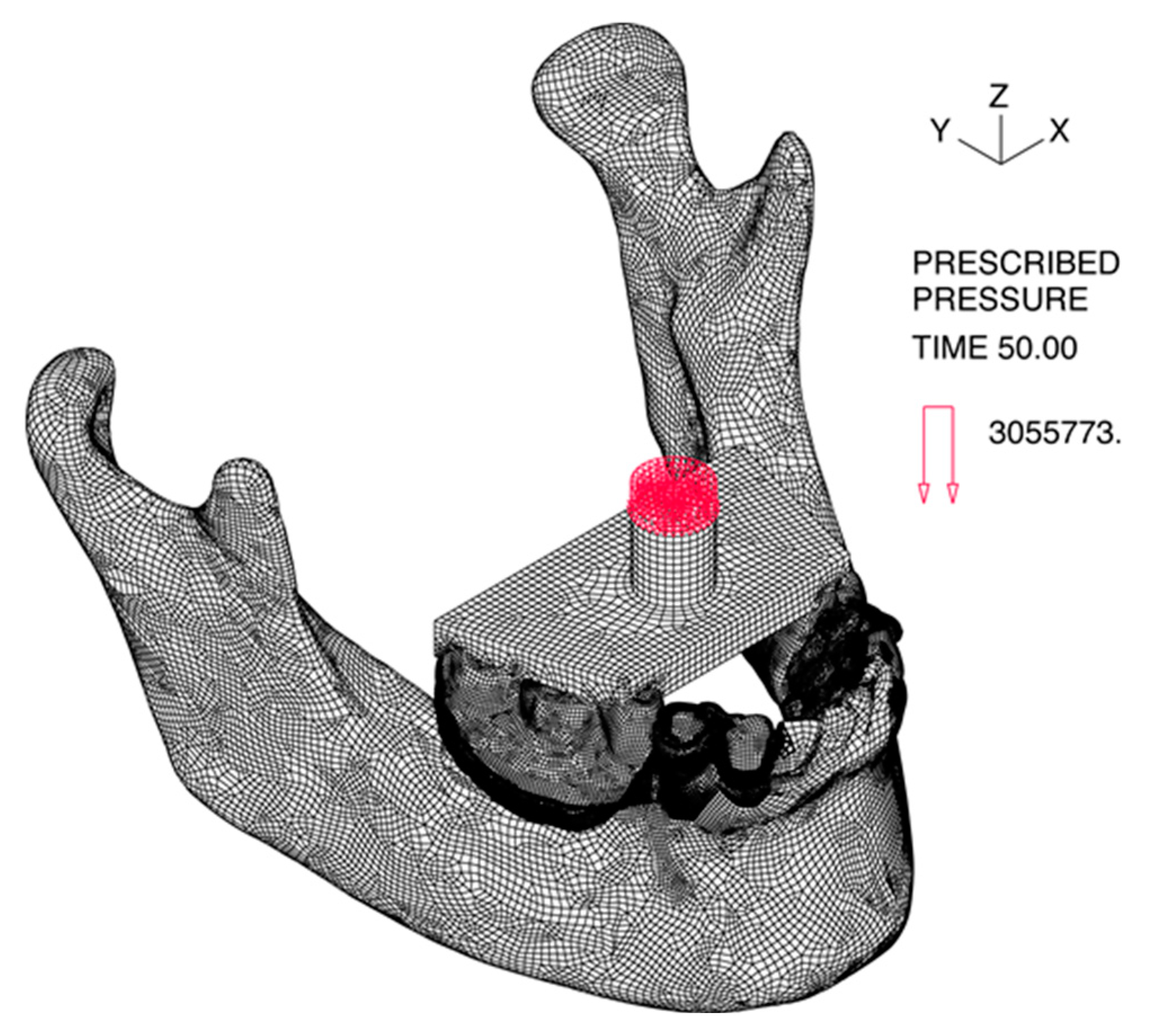
The load was applied on a 78.5 mm
2 circle in the geometric center of the loading plate as a homogenously distributed pressure corresponding to a 240 N load in the Z direction, as shown in
Figure 2. The loads were applied gradually to avoid dynamic effects and convergence problems. The automatic time stepping procedure was used for the model CONVENTIONAL RPD to improve the convergence rate.
3. Results
Simulations of both models of IARPD successfully completed all time steps of the computation, whereas the simulation of the CONVENTIONAL RPD stopped at the incremental 66-step, due to excessive deformation of the tissue. Hence, the step 50, corresponding to a 120 N load, was the basis for comparisons among models. These comparisons were based on the qualitative interpretation of the band plots and quantitative analysis of the values of displacement, strain and stress of different element groups at the same load step.
The distribution of values of the three models was statistically analysed using the one-way ANOVA test of the Statistical Package for Social Sciences (SPSS) version 23.0. Post-hoc comparisons were made using the t-test for independent samples with Bonferroni correction. The significance level was set at 0.05.
3.1. Overal Displacements
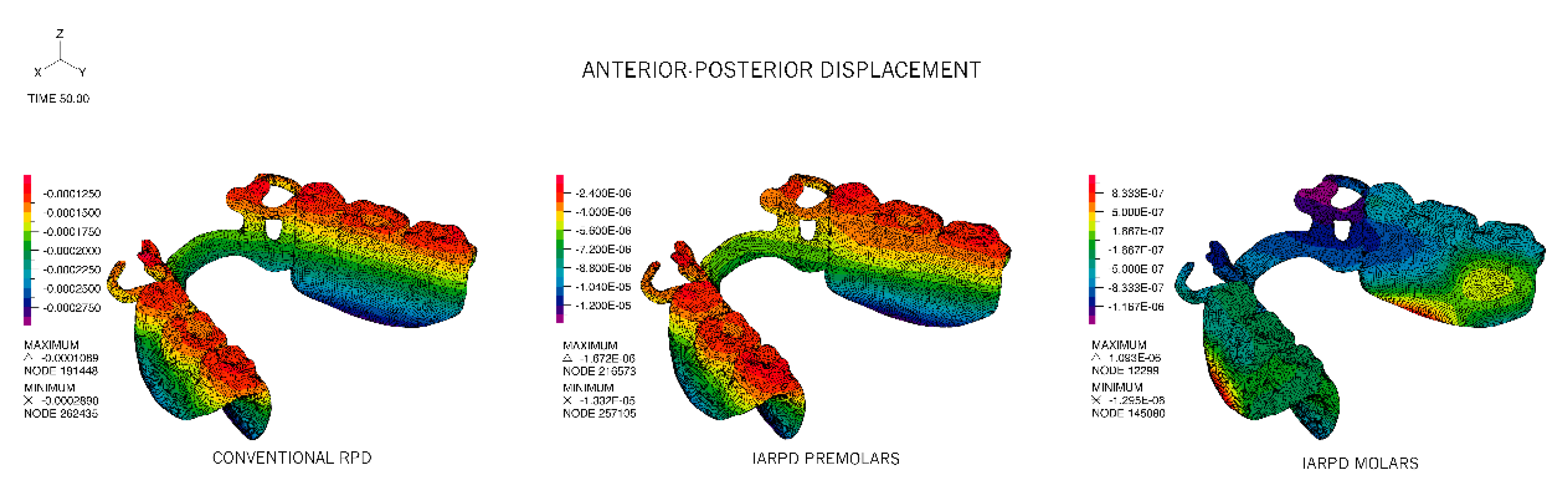
The CONVENTIONAL RPD model revealed significant displacement in the sagittal plane, particularly noticed on the bottom of the acrylic where the highest absolute values were identified. All displacement occurred in the posterior–anterior direction (towards the natural teeth) and showed the least value in the occlusal surfaces of the acrylic teeth and on the occlusal rests that seat on the premolars
Figure 3, with a mean value of −190 ± 36 μm. The same pattern was identified in the IARPD PM model. Nevertheless, comparison of the values registered for the two homologous bands reveals that the displacements in the IARPD PM occur at a scale of hundred times smaller. The mean displacement in the sagittal plane for the IARPD PM model was −6.30 ± 2.33 μm.
In the IARPD MO model, displacements were registered from posterior to anterior with approximation to the remaining teeth (negative values), but also from anterior to posterior, however, most elements showed no displacement (as represented in light green). The highest movement of approximation to the remaining teeth was observed in the clasps and occlusal rests whereas the opposite movement was detected in the portion of the lower border of the acrylic between the abutment tooth and the implant.
Displacement in the Z direction was mainly responsible for the displacement magnitude of the RPDs, accompanying the direction of the applied force, i.e., downwards, in the direction of the underlying soft tissues. For CONVENTIONAL and IARPD PM models there was a noticeable trend of sinking of the acrylic portion of the RPD with displacements increasing with the increase of the distance to the supports (teeth or implant). Despite the similar pattern of vertical displacement of these two models, the tissue ward movement was higher in the CONVENTIONAL RPD model and the difference between models reduced from being 250 times higher in the most anterior portion of the framework and acrylic to 40 times in the distal extreme of the two prostheses. In the IARPD MO model, on the contrary, the least vertical displacement was registered in the region of the implants and the largest displacements in the apical direction were associated with the anterior region, where the framework contacts the abutment teeth. Mean values for the three models were, respectively, −710 ± 84 μm, −14 ± 6.4 μm and −4 ± 0.81 μm. The corresponding maximum values were −900, −28.4 and −5.5 μm.
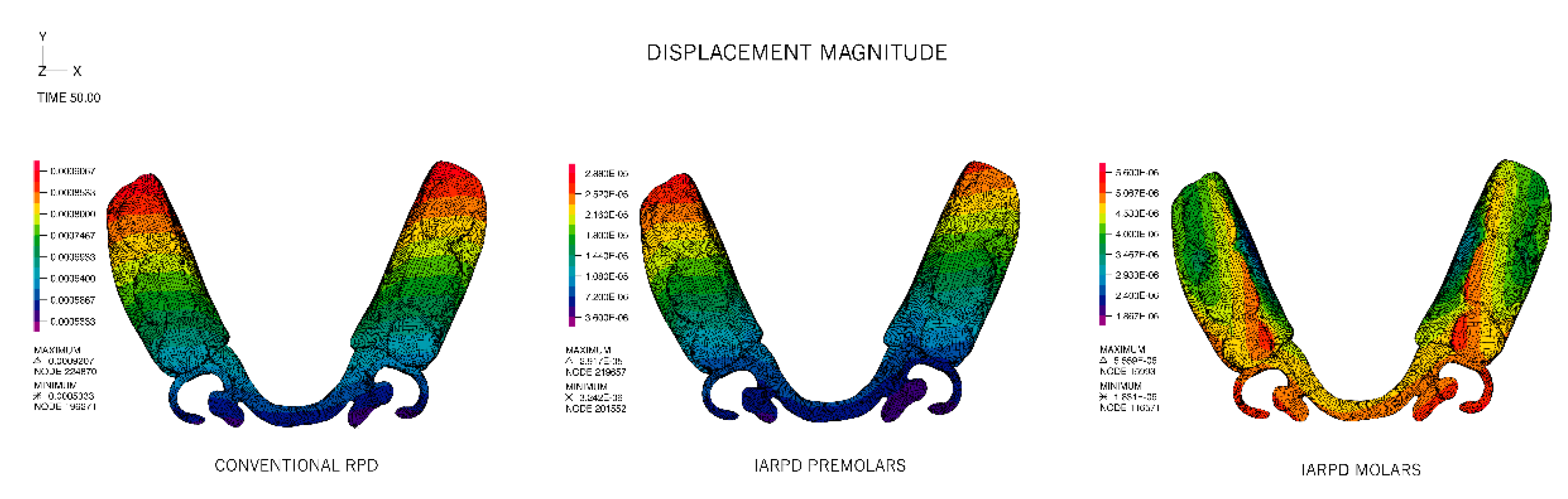
The magnitude of displacements is plotted in
Figure 4. In conformity with the reported magnitudes for the horizontal and vertical displacements, the CONVENTIONAL and IARPD PM models presented similar distributions. Overall, these distributions were symmetrical and f the highest displacement taking place in the acrylic portions, increasing from mesial to the distal free end of the acrylic flange. Though also symmetrical, the IARPD MO model revealed the highest displacements in the most proximal portion of the acrylic and in the clasp assembly and indirect retainer. The lowest displacements were found in the vicinity of the implant attachment.
Statistically significant differences were found between the mean values of displacement of the three groups (
p < 0.001),
Table 4. Mean values of displacement of the IARPD MO were 4 ± 0.8 μm, ranging from 2 to 6 μms and were significantly lower than any other model. Despite the similarities in distribution of displacements in the CONVENTIONAL and the IARPD PM models, the values of those groups were also statistically different, with means of 730 ± 80 μm and 20 ± 6 μm respectively. Pairwise comparisons of the three models are detailed in
Table 5.
Loading of the acrylic portion of the prosthesis induced displacement of the abutment teeth by means of the contact with the framework, through the occlusal and cingulum rests. For the two implant-assisted models the largest component of the displacement was vertical and in the direction of the load, whereas for the CONVENTIONAL RPD model, the largest displacements were consistently distributed between vertical and anterior-posterior, as can be seen in
Table 6. In this case, the abutment teeth not only move in the direction of the load but also present tipping towards the edentulous span.
The addition of the implants to the rehabilitation have significantly reduced the magnitude of displacements of the abutment teeth and the lowest displacements were registered in the IARPD MO model.
3.2. Overall Stresses
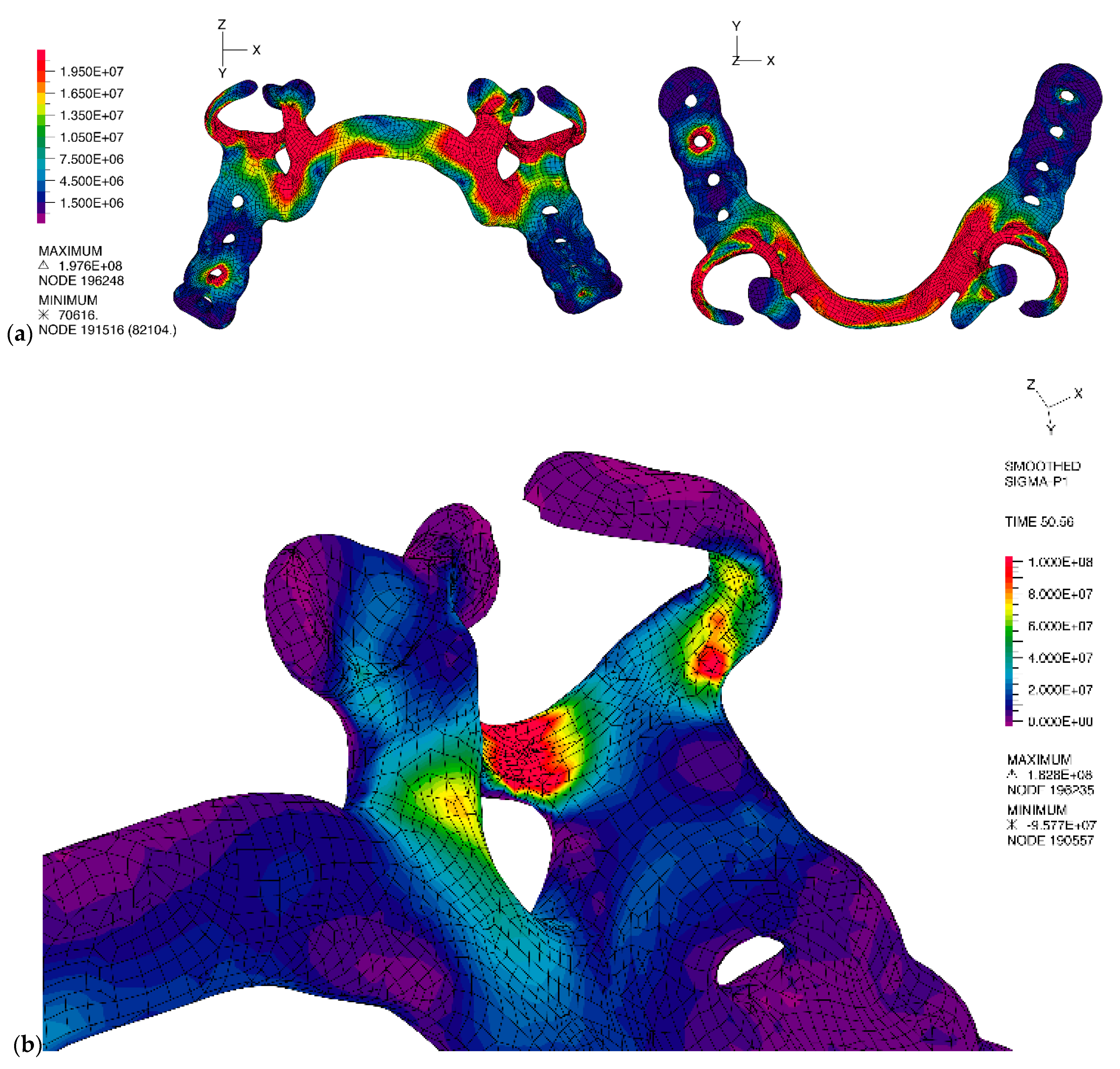
The stress distribution in the frameworks was different for all three models. The CONVENTIONAL RPD model presented the highest values of effective stress, showing extensive areas with values superior to 10 MPa, as presented in
Figure 5a. The mean von Mises stress was 11.3 ± 14 MPa, ranging from 0.8 MPa to 200 MPa. Critical areas were at the direct retainers, namely the rigid portion of the retentive clasp and the minor connectors, as well as the major connector, where the maximum principal stresses are of tensile type, as can be seen in
Figure 5b.
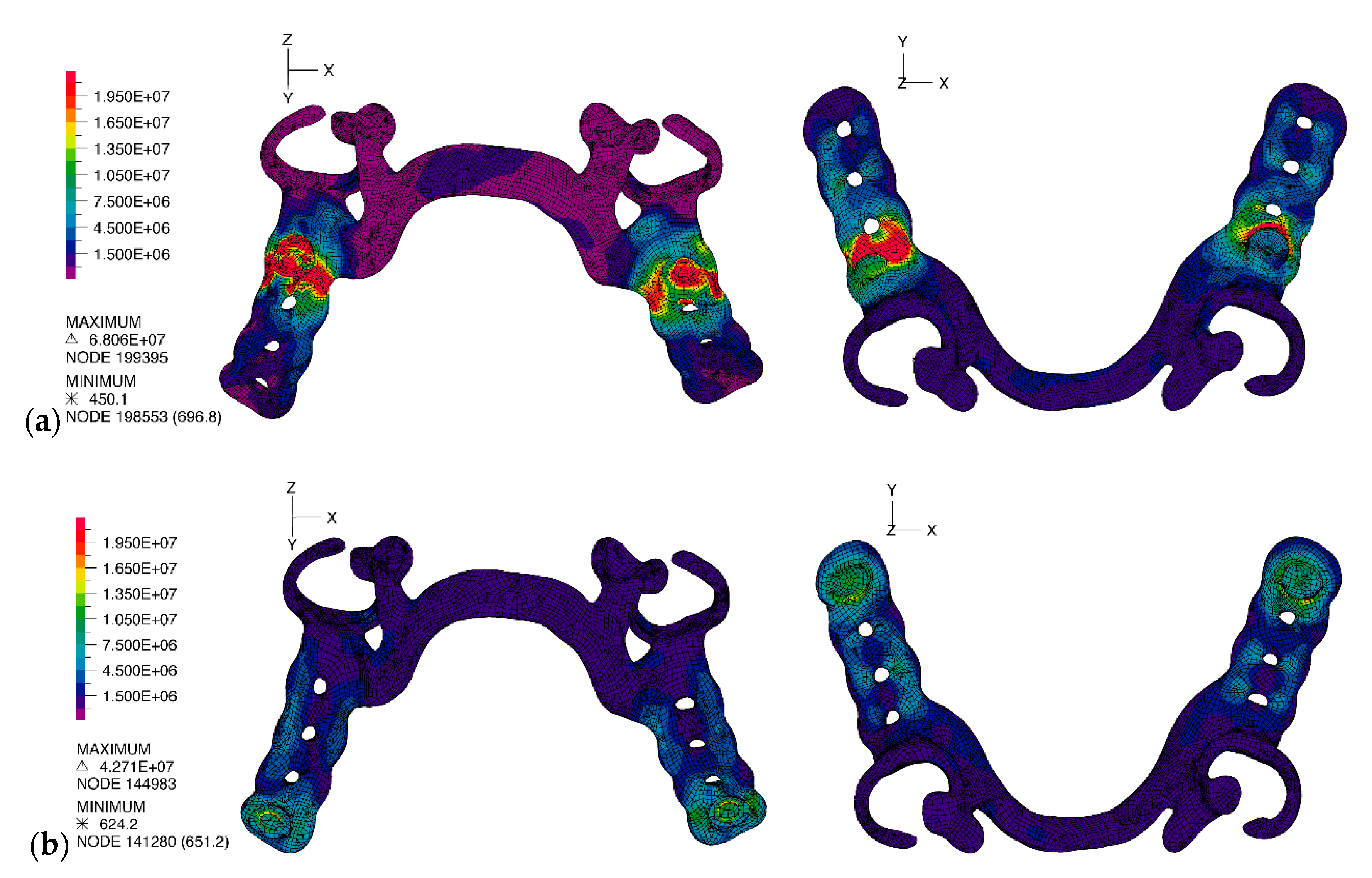
In the case of the IARPD PM and IARPD MO models, there was no high stress accumulation in the direct retainers or major connector. The highest stress accumulation was in the interior portion of the matrix and surrounding material, as observed in
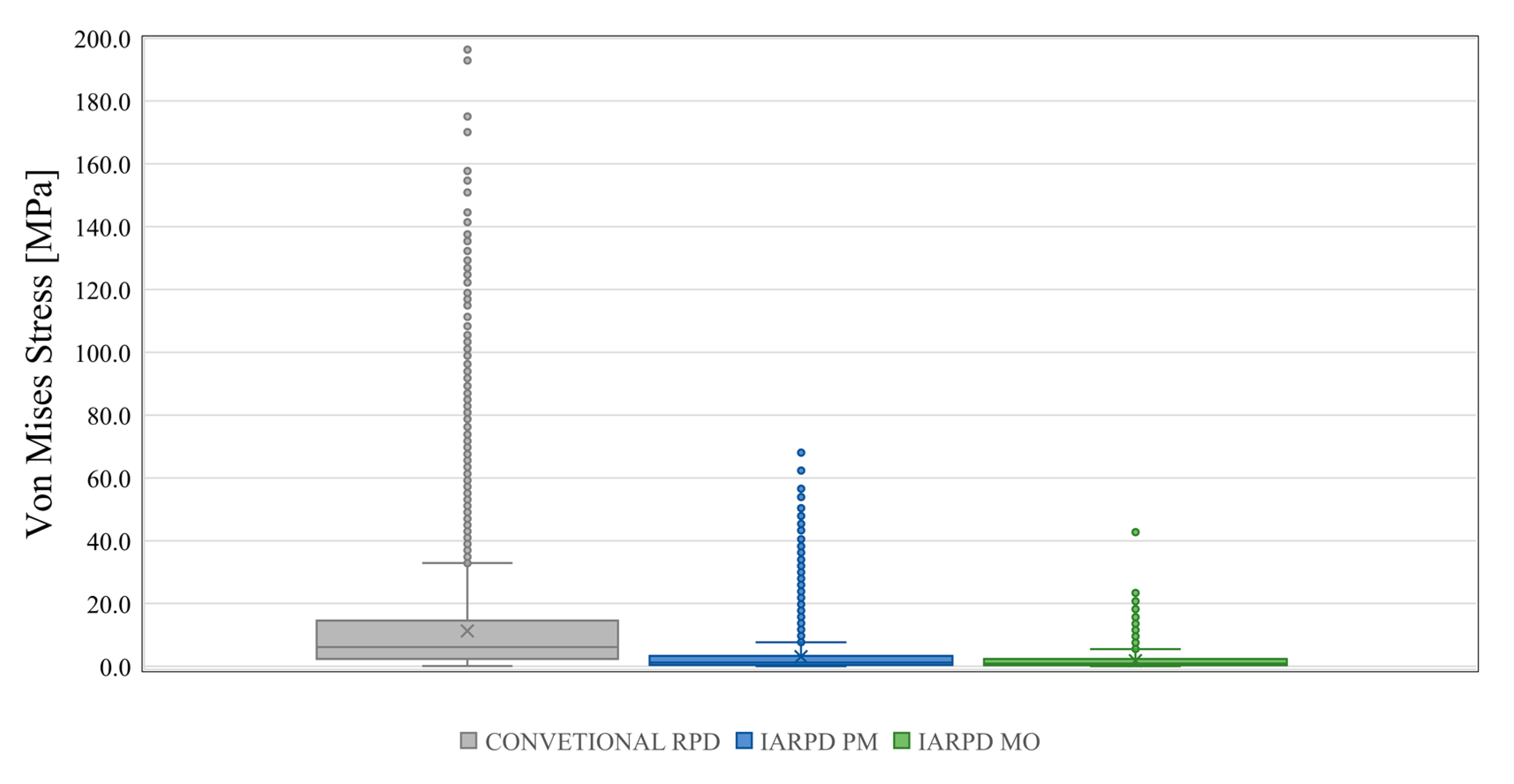
Figure 6, and, generally, was lower than in the CONVENTIONAL RPD model. For the IARPD PM model, the mean von Mises stress value was 3.04 ± 4.96 MPa, ranging from 462 Pa to 68 MPa, while in the IARPD MO model the von Mises stress value was of 1.81 ± 2.37 MPa, ranging from 651 Pa to 43 MPa. The values distribution of the three models are shown in the box plot graphic presented at
Figure 7. One-way ANOVA detected significant differences between models, F(2, 77087) = 8740,
p < 0.001. All three models were found to be different in the pairwise comparisons presented at
Table 7.
4. Discussion
The present study focused on the evaluation of the stress patterns associated with distal extension removable partial dentures when submitted to static bilateral and homogenous loading of the artificial acrylic teeth. Three models were compared, one featuring a conventional removable partial denture (CONVENTIONAL RPD) and two featuring implant-assisted removable partial dentures, with the implants placed either in the proximal portion (IARPD PM) or in the distal portion of the edentulous areas (IARPD MO). Although some studies addressing the finite element analysis of implant-assisted removable partial dentures have been published [
17,
18,
33,
34,
35,
36], the present work is, according to our knowledge, the first non-linear analysis presenting a three-dimensional comparison with conventional extension base removable partial dentures and also the first evaluating the effect of implant position on stress and strain on a patient-based 3-D mandibular model.
The 3-D nature of the CONVENTIONAL RPD model of this study provided a better understanding of the mechanics of the conventional extension base RPDs when occluding the acrylic portion of the prosthesis. Moreover, the patient-based construction method together with the geometric complexity associated with the model and the specific material characteristics also allowed pairing with the clinical phenomena taking place in Kennedy class I denture wearers, even though no intra-oral or clinical measurements were taken as part of a validation procedure. The similarity of the tissueward displacements of the denture base at the CONVENTIONAL RPD model with those visually detected by Jorge et al. [
37] and Frank et al. [
38] contributes to the proximity of the FEM results and those reported in clinical and experimental studies. It is the case of the maximum vertical displacements of the framework and denture base of 0.5 mm (500 μm) observed in the CONVENTIONAL RPD model that is in line with the 400 μm reported by Jin et al. [
39] for the posterior portion of unilateral extension RPDs and superior, but concordant, with the 250 μm registered for a similar maxillary prosthesis [
40].
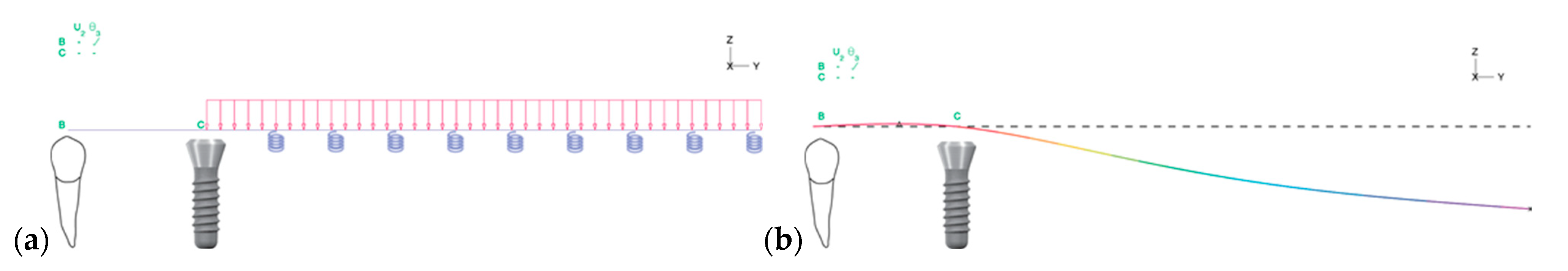
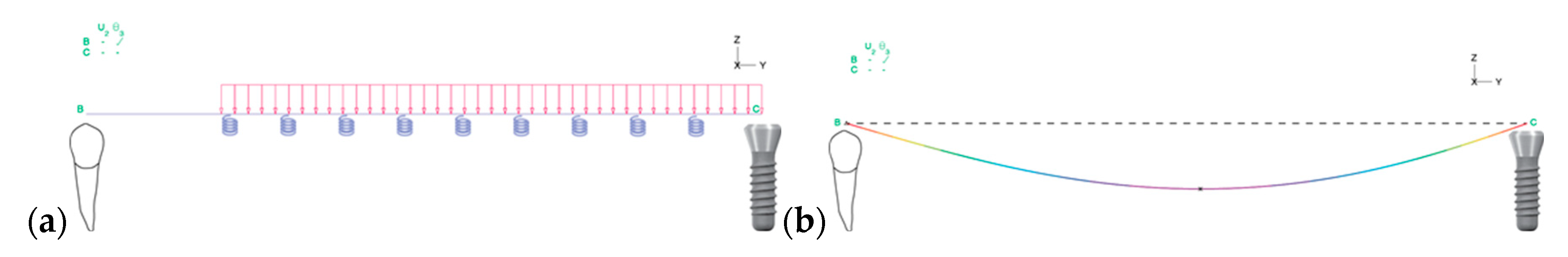
The pattern, the consistency and the magnitude of the displacements registered to the buccal, mesial and apical directions were not unexpected for a prosthesis with non-rigid retainers. The clasp systems applied to the abutment teeth are usually designed to have a stress-releasing effect, allowing the tissueward rotation of the RPD bases around the axis passing through the occlusal rests, without torqueing the clasped teeth. When the distal extension base is loaded, the occlusal rests of the prosthesis act as hinge support, resisting vertical and horizontal loads, but are unable to resist to the moment generated by the vertical loads. Therefore, the prosthesis and tooth ensemble can be interpreted as a Euler-Bernoulli beam problem [
41,
42], represented in
Figure 8.
In the correspondence of mandibular Kennedy class I patients rehabilitated with CONVENTIONAL RPDs to a classic mechanics problem, the angle of rotation of the prosthesis can be related to the cross-section rotation angle (
) of a cantilever beam and the vertical displacements, in any cross-section of the acrylic, can be given by the deflection of the Euler beam at any point in the
y axis by [
42]:
, where
q is the load applied,
is the beam bending stiffness and
is the total length of the beam. Similarly, the vertical displacement of the acrylic base in the CONVENTIONAL RPD depends on the axial position of the acrylic section and increases as we move away from the support at the occlusal rests. This effect explains the increasing vertical displacement of the CONVENTIONAL RPD from the mesial to the distal portion of the acrylic base, where the maximum displacement is registered.
This interpretation of the variation of displacement can also be applied to the IARPD PM model. The implant–matrix assembly placed in the mesial portion of the edentulous span acts, also, as a hinge support while the remaining section of the acrylic is unsupported. Differences in the magnitude of displacements of the CONVENTIONAL RPD and IARPD PM models are related to the rigidity of the supports. In fact, due to the stress-releasing properties of the direct retainers applied on the abutment teeth, in the CONVENTIONAL RPD the support is non-rigid whereas in the IARPD PM there is a rigid support, resulting from the ball attachment-matrix assembly, that blocks the free rotation of the framework and acrylic (
Figure 9), but still allows deflection under occlusal load.
This explains not only the reduction of displacement towards the underlying mucosa, but also why the reduction of the displacement is higher in the most anterior portion of the acrylic and in the direct retainers (250 times) than at the most distal portion of the acrylic (40 times), inferred from the proportion between scales of vertical displacements plotted for the two models in
Figure 4. The pattern of displacement of the IARPD MO model differs from those previously described, due to the different positioning of the rigid support,
Figure 10.
The direct retainers and the ball attachment–matrix assembly act as non-rigid and rigid supports for the extension base, respectively. Loading of the acrylic portion of the IARPD, in this situation, is comparable to loading a simple supported beam, that is, a beam that is supported at both ends. The higher rigidity of the system leads to the modification of the pattern of displacements and to a reduction higher than 100-fold of the mean vertical displacement of the acrylic elements on the CONVENTIONAL RPD model (−710 ± 84 μm in the CONVENTIONAL vs. −4 ± 0.81 μm in the IARPD MO). The highest displacement of the prosthesis of the IARPD MO model is therefore registered in the acrylic middle span, between the direct retainers of the framework, where the support is non-rigid allowing some free movements, and between the support provided by the implant (rigid), as simplified in
Figure 10. Such effect was also reported by Shahmiri at al. [
34,
35]. The present study registered the smallest displacements in the region of the abutment–matrix contact, where the highest rigidity is provided to the system, which was appointed by the aforementioned authors in other publication as possible points of rotation [
34].
The different patterns of displacement generate different stress distributions on the framework of the prosthesis in the three models. The highest stresses concentrate in the areas of the framework with the lowest possibility of movement, that is the areas of support, either non-rigid in the CONVENTIONAL RPD model, provided by the direct retainers, or rigid in the IARPD PM and IARPD MO models, provided by the ball attachment-matrix contact. In the framework of the CONVENTIONAL RPD model more than 25% of the equivalent von Mises stress values were superior to 1 MPa, and values over 20 MPa rising to 200 MPa spread through the direct retainers (clasps and occlusal rests), minor connectors and major connector. This distribution of von Mises stresses in the CONVENTIONAL RPD model is consistent with the areas where most of the technical problems are detected in the re-examination of denture-wearing patients, which include loss of retention of the clasps due to permanent deformation, as well as their fracture, and deformation of the minor and major connectors. The correspondence between these two findings is particularly perceptible in the clasps, which are associated with a large fraction of all technical failures and, simultaneously, present high tensile stresses, namely in the transition from the non-flexible to the flexible portion of the clasp. The clasps may lose retention force, because of multiple deflections, and present gradual loss of elasticity [
43]. Experimental studies point to permanent deformation or fracture of chromium–cobalt specimens with at least 0.5 mm deflection after a limited number of cycles, ranging from 20,000 to 30,000 [
44,
45,
46]. In these specimens, fracture location is in close relation to the areas with the highest tensile stress distribution [
46] and is concordant with the results obtained in the present study for the CONVENTIONAL RPD model.
The installation of implants in the edentulous areas to promote support and retention to the RPD resulted in a 3 and 6-fold reduction in the mean equivalent stress in the frameworks of the IARPD PM and IARPD MO models, respectively. Modelling of these implant-assisted cases was conducted on no other design modification than the addition of the matrix to the framework, which led to transferal of stress from the direct retainers and minor connectors to the matrix, where the connection to the implant was modelled as rigid. This stress distribution across the framework differs from that reported by Shahmiri & Das [
47] because of the different geometries studied. Those authors did not incorporate the attachment matrix within the framework therefore, the stress distribution resembled that of a conventional removable partial denture, where in the minor connectors remain the most stressed areas. Nevertheless, clinical studies on implant-assisted removable partial dentures are consistent with our results, reporting a reduction of prosthodontic events in the retainers and simultaneously greater need for maintenance associated with the implant-related components, the patrix and matrix, where the finite element analysis revealed higher stress accumulation [
48,
49]. In a retrospective study with a mean follow-up of 8 years (ranging from 3 to 16 years) of patients rehabilitated with implant-assisted removable partial dentures to replace three teeth at both mandible sides, Jensen et al. [
50] compared a cohort of patients with implants placed anteriorly, in the position of the premolars, and a cohort of patients with implants placed posteriorly, in the position of the second molars. The authors reported higher rate of technical failures associated with the implant assisted removable partial dentures with support in the premolars, yet overall, relatively low.
The differences in prosthodontic performance between premolar and molar implant support could be associated not only with stress distribution in the two frameworks, as identified in the finite element analysis, but also with the type of forces developing within the structure. In fact, the IARPD MO model presents virtually no areas of equivalent stresses superior to 20 MPa (
Figure 6b), while such stresses spread around the matrix of the IARPD PM model, represented as red areas in
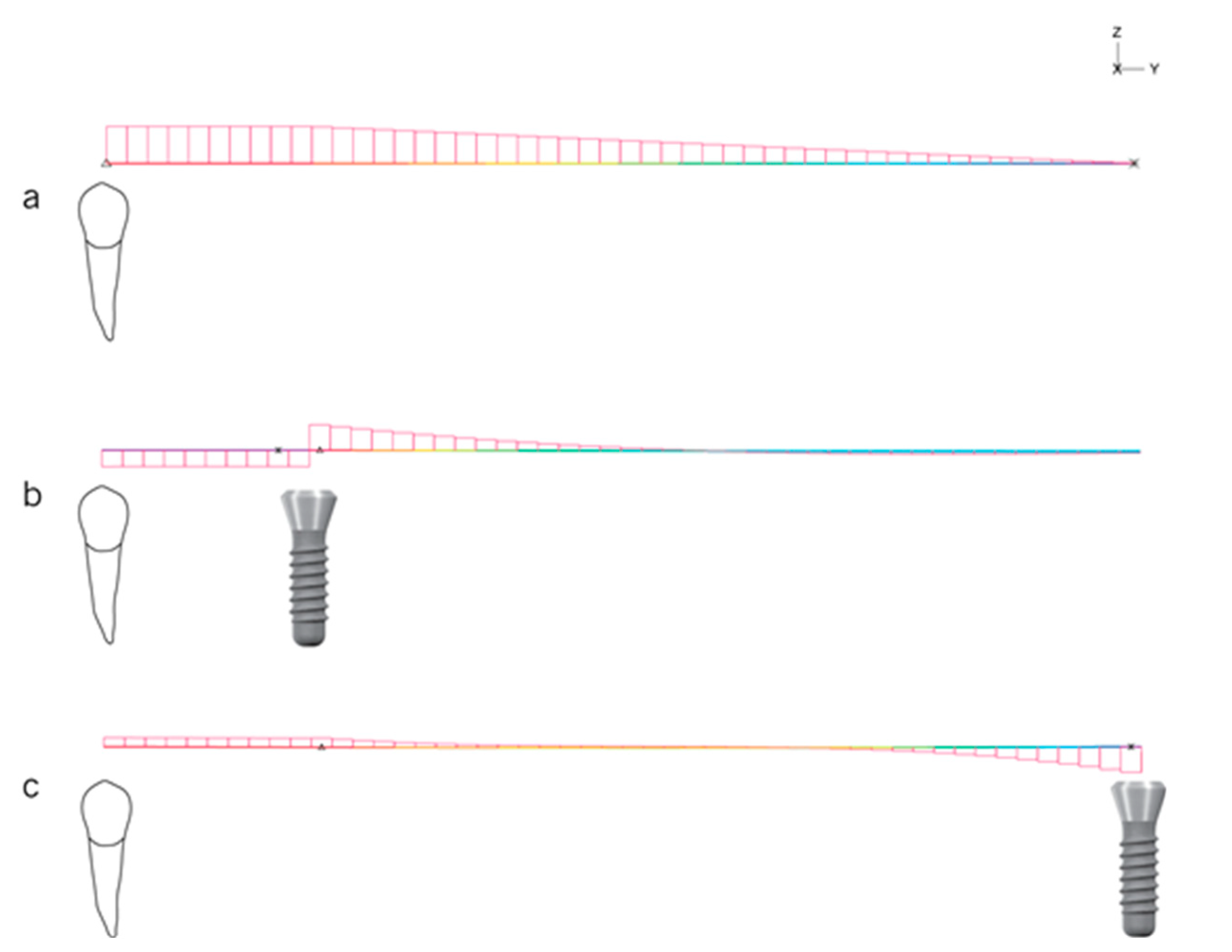
Figure 6a, but the mechanical disposition of the system might be the most important factor to consider. Indeed, when considering the adaptation of the Euler–Bernoulli beam problem, the three models generate different shear forces and bending moments in the supports (teeth and implants) and framework of mandibular extension base removable partial dentures either under concentrated or distributed loads. The use of dental implants to promote support to the framework promotes a significant reduction of the disrupting forces acting within the structure of the framework transversally to the occlusal plane, that is, the shear forces, but the effect is modified according to the position of the implant within the edentulous area, as depicted in
Figure 11.
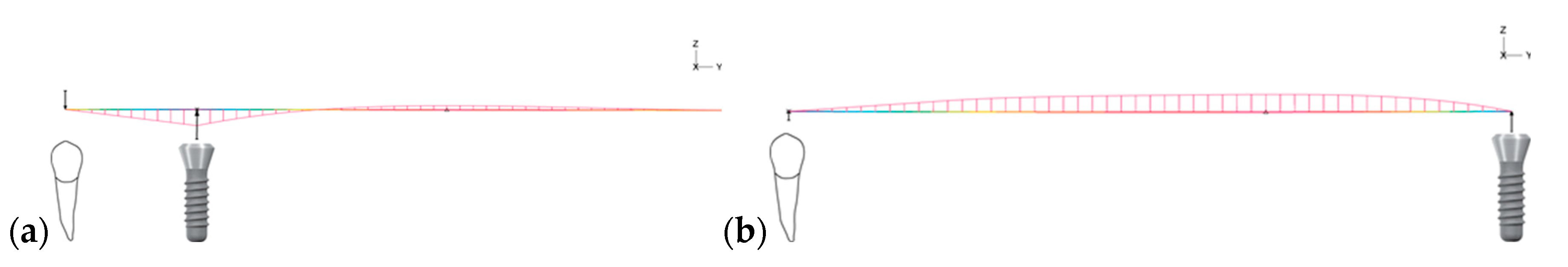
This is a similar observation to that described in the theoretical study of Oh et al. (2016). The authors reported that the peak shear forces are higher when the extension bases receive no additional implant support (CONVENTIONAL RPD model) and the least when the implant is placed distally in the edentulous span, which corresponds to the IAPRPD MO model, with a significant reduction in value of more than 90%. It is interesting to notice that in the IARPD PM model the shear forces invert the signal in the section corresponding to the implant support. Accordingly, the reaction of the structure to the bending effect of the occlusal forces (bending moment) is maximum at the implant in the IARPD PM model, indicating not only a critical point of the structure that undergoes simultaneous compressive and tensile stress but also that the implant supports most of the applied load (
Figure 12).
In fact, this peak value of the bending moment could be responsible for the higher deformations in the implants in the IARPD PM model. In this case, the most anterior portion of the structure, corresponding to the span of an overhanging beam delimited by the tooth and the implant, undergoes hogging, i.e., is subjected to tensile stress. Simultaneously, the unsupported portion of the structure undergoes sagging, that is, is subjected to compressive stress. These simultaneous effects translate into a negative bending moment on the first portion of the structure/framework, which is maximum (in absolute) over the implant (rigid support), and that explains the deflection of the ball attachment towards the distal side (towards the portion of the denture that has mucosal support). Successive cycles of deflection of the ball attachment due to loading of the prosthesis result in stress fatigue of the ball attachment, increasing the susceptibility technical problems [
51], either in the attachments or in the frameworks and implants of IARPD prosthesis with implants placed anteriorly.
The hogging effect in the anterior portion of the structure in the IARPD PM model is also responsible for the opposing forces acting at the abutment tooth and implant. The counterforce acting on the abutment tooth (downwards arrow) reflects the tensile nature of the resultant forces acting over that support, i.e., the tooth is “pulled” upwards in the contact areas between the reciprocal arm of the retentive clasp and the lingual surface of the premolars. A similar effect, presented by Chen et al. [
30], was found for the two most anterior/mesial implants in 4-implant overdentures for the rehabilitation of complete edentulous mandibles. The authors report that the anterior/mesial implants experience pull-out tensile forces to balance the bending moment at the posterior/distal implants. Conversely, in the schematic representation of the IARPD MO model the shear force is maximum at the implant support (
Figure 12, represented in c) but the bending moment is null (
Figure 12b). As observed in the deformed representation (
Figure 10), the whole span between supports is bent due to the applied vertical distributed load and the maximum bending moment is approximately at the midpoint of the span. It is easily possible to infer that the wider the span, the greater the sagging effect of the structure and the higher the risk of failure, which should be considered in the case of extensive edentulism, namely when 4 teeth are missing per edentulous span.
Limitations of the present work are mainly related to the nature of the study and possibility of transposition to the clinical setting. For instance, in this study the behavior of RPDs in the oral cavity was simulated assuming that the framework and abutment teeth were not rigidly bonded, allowing sliding, whereas the ball attachment and the matrix incorporated in the framework were rigidly attached, ensuring a total transmission of loads from the contactor to the target surfaces. This was a technical option to improve convergence of results and approximation accuracy but limited the possibility of free rotation around the ball attachment which is clinically observed [
52,
53,
54] when the acrylic teeth are loaded. Future research should address other parameters that might change the magnitude of all effects emphasized in this work, namely the type of attachment system, the height of the corresponding abutment [
55,
56,
57] and the type of implant (one or two-piece). Notwithstanding this, it is very clear that the addition of one implant to the denture bearing areas, regardless of the position, is paramount for the reduction of the displacements of the prosthesis and, consequently, of the abutment teeth mobility.


