1. Introduction
It is now generally accepted that, in order to properly assess the structural response, the seismic actions must include, besides the horizontal and vertical translational components, also the rotational components of ground motion [
1].
The ground rotations about the horizontal axes, x and y, are usually named rocking, while the rotation about the vertical axis z is called torsion. Even a small contribution of rocking excitations around any horizontal axis may dominate the vibrations of a high slender building, which are additionally magnified by P-Δ effects.
Many authors have contributed to the research on seismic rotational components (see, e.g., [
1,
2,
3,
4,
5,
6]). New procedures were developed on how to describe this seismic ground motion and how to quantify its effects on the structural response (see, e.g., [
7,
8,
9,
10,
11,
12,
13,
14]. The seismic rotational components can be deduced from:
(a) Considerations of the seismic source and wave propagation.
For example, Basu [
15,
16] uses a method of deconstructing the translational time series into body waves, which are in turn reassembled to generate rotational time series. A mathematical model based on a representation of soil impedance and contributions of body waves is presented in [
17].
(b) Records of rotational ground motion.
A simple yet effective technique is presented to explicitly recover the rotational motions from recorded horizontal accelerograms [
18]. Much progress has been made with recent developments in rotation sensors, producing direct measurements that could be compared with theoretical expectations or used to predict the responses of structures [
19].
(c) Code approximation.
One of the first worldwide standards that codifies these actions is EN 1998-6 [
20,
21]. These effects have to be taken into account in the case of tall structures situated in regions of high seismicity. The rotational component is defined in this standard as a multiplier of the horizontal response spectra. This simplification depends upon the shear-wave velocity of the top 30 m of the ground and upon the soil compliance and not on the seismological parameters of the expected earthquake and its detailed wave propagation characteristics. It is now acknowledged that it depends also on the waves with higher phase velocities associated with the deeper ground layers [
14]. These engineering code formulas should be calibrated and reconciled with the results of the latest empirical research on the rocking component of ground motion.
The rocking response spectrum proposed in Eurocode 8 Part 6 for slender structures was compared with seismic time history response analyses of an R/C chimney, yielding its substantial conservatism compared with the time history response computations using real records of 6-DOF strong ground motion [
10]. Time-history analyses with real measured seismic records are therefore very important for future calibrations of seismic design codes using response spectrum approach.
Studies show, e.g., [
13], that the contribution of rotational excitation effects in the response of slender towers is substantial and can be of the same order as horizontal excitations.
The primary factors affecting the structural response are coupled translational and rotational motion, the frequency content of these components and their interaction with dynamic characteristics of the structure and soil [
18].
The actual interaction of translational and rotational excitations in the structural response of a slender tower depends on the frequency contents and actual signs and directions of these two excitations. The proper proportion of horizontal-to-rotational intensity is crucial to properly assess the contribution of rotational effects in overall seismic structural vibrations [
9].
According to some studies [
10], the presence of seismic rotations about the horizontal axis sometimes increases the overall response (up to 30%), but sometimes it decreases the combined seismic response. The most important structural influences are the fundamental natural period and the effective height of the analyzed structure. So, the application of the familiar rule the square root of the sum of the squares (SRSS) to combine the horizontal and rocking effects may underestimate the overall seismic response.
Bonev et al. [
7] studied the determination of the sufficient number of modes considering the bending moment and shear force, the influence of a large number of degrees of freedoms and soil conditions.
A general algorithm for approximate evaluation of soil–foundation–structure interaction effects is provided by Bonev [
8].
New formulas that consider the earthquake rotational motion effects in the seismic loading of low- to medium-rise multistory buildings were presented by Falamarz and Ghafory [
11]. The effects of soil–structure interaction and foundation type was studied by Falamarz and Ghafory [
12].
In this paper, the focus is on practical and simple procedures that can be used for estimation of the measure of how the rotational components of ground motion on buildings is significant. Simple equations are developed that take into account a few parameters, e.g., estimation of the mass and stiffness of the building including soil characteristics and the type of the structural system and the height.
2. The Response Parameter Defining the Contribution of Rotational Seismic Component
The ratio of maximal seismic effects on a structure, taking into account the translational and rotational components of the earthquake motion, can be expressed as
where
is the seismic effect assuming only translational components;
is the seismic effect assuming only rotational components;
is the SRSS combination of translational and rotational components.
This ratio can as well be expressed as the ratio of the maximal design moment in the end fixity, when the structure of the mast, tower, chimney, or high-rise building is approximately considered as a cantilever
where
is the inertial force from translational effects at story ;
is the inertial force from rotational effects at story ;
is the elevation of the story from the foundation.
is a dimensionless parameter. We assume the rough estimate of the importance of the rotational effect, namely, if is up to 1.1.
3. General Simplified Procedure
The following simplified assumptions are used, which are mostly fulfilled for slender structures such as towers, masts and chimneys:
The contribution of the first vibration mode is most important;
The mass and stiffness are evenly distributed along the height, or the changes of it are gradual.
Based on these assumptions, we can express the seismic effects from translational and rotational components of ground motion by inertial forces in the particular levels (storeys).
For translational components of ground motion, it follows
where
is the maximal deflection of the -th story under vibration with frequency from the effects of translational components;
is mass concentrated in level .
Using decomposition into eigen modes, we can express
as
where
is the coordinate of the -th vibration mode shape at location ;
is the vector of the -th vibration mode;
is a unit vector;
spectral displacement coordinate;
spectral acceleration coordinate.
After substitution of Equation (4) into Equation (3)
where
is the participation factor of mode shape j under translational excitation.
Similarly, for the rotational components of ground motion
where
is the maximal deflection of the
-th story under vibration with frequency
from the effects of rotational components of ground motion;
is the maximal rotation of foundation about the horizontal axis;
is the spectrum of rotational acceleration response about the horizontal axis [rad/s
2] according to EN 1998-6 (2005), cl. A(5); with shear modulus
and soil density
;
is the shear wave velocity (11).
Inserting Equations (8)–(10) into Equation (7) we can write
where
is a vector of the heights of individual stories. After arrangement
where
is the participation factor of shape
under rotational excitation.
After substitution of Equation (10) into Equation (13), we obtain
When we substitute Equations (5) and (15) into Equation (2), we obtain
Some studies had shown that the periods estimated on simple equations provided by earthquake design codes vary significantly from the periods computed using ambient vibration records on the monitored buildings [
22,
23]. By taking the effect of the building height and the number of stories also, new improved formulas can be developed [
24]. When we use the well-known formulas of [
25], adopted also in EN 1998-1 [
26,
27], cl.4.3.3.2.2(3), the terms for the fundamental period
are
where
for space steel frames with moment transfer;
for space R/C frames and for eccentrically braced steel frames;
for other structures;
is the height of the structure from the top of a stiff basement.
Of course, the period of a structure exposed to a strong earthquake, when many plastic hinges are formed, is different from the one that is analyzed or measured by ambient vibrations.
The effects of changes in the eigen-period due to damage are more or less roughly taken into account by considering a structural system with only 1/2 of its original stiffness.
According to EN 1991-1-4 [
28], F.3(1) fundamental mode shape
of slender masts, towers or buildings can be estimated as
where
is the height from the foundation or from the top of a stiff basement;
for slender frame structures with non-bearing walls;
for buildings with a central core and peripheral columns or larger columns with shear bracings;
for slender cantilever buildings with central R/C core;
for towers and chimneys;
for lattice steel towers.
Equations (6) and (14) can be written in integral form as
where
[kg/m] is mass of unit height.
Considering the first shape and substituting Equation (19) into Equations (20) and (21), and after integration, we obtain
Substituting Equations (22) and (23) into Equation (17), we obtain
This equation was used for the calculation of the value, which reflects the contribution of rotational components of ground motion into the total seismic response based on the height of the structure, ground type and structural type.
The influence of the soil category on the fundamental period is not included in Equation (19). This is simply taken into account in the following section. It is not likely that high-rise buildings will be constructed on soil category D or worse. That is why only three soil categories were assumed further (
Table 1).
4. Influence of Soil Stiffness—Simplified Analysis
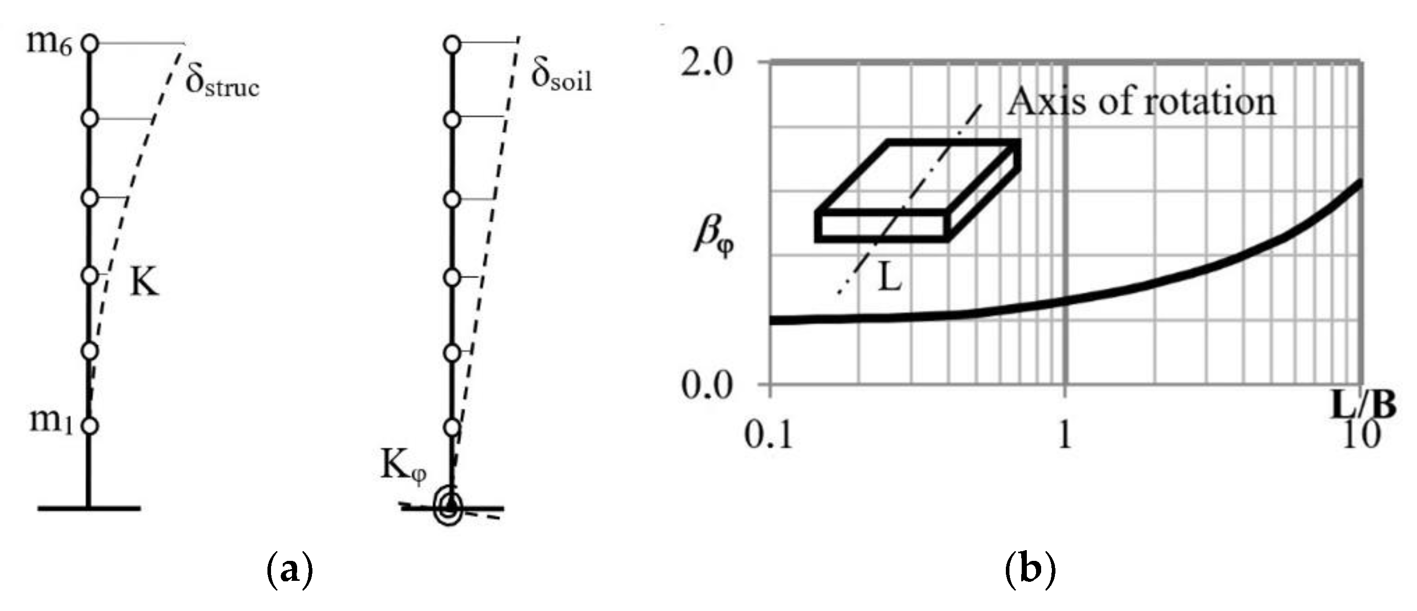
In order to assess possible changes of the soil stiffness, simple modification can be carried out. Total displacement of the system can be assumed as the sum of both flexion of the structure and rocking displacement due to foundation rotation (
Figure 1a)
Equation (18) has then been modified. The fundamental period after accounting of soil stiffness is
where
Rotational stiffness of the soil has been assumed according to [
29]
where
It is easy to express the stiffness of an SDOF system
The only difficulty is to assess the mass for the SDOF model. For simplicity reasons, it would be appropriate if this value also depends only on one parameter, namely, the total height of the building
. Assuming mainly buildings, the plan-view ground-level dimension
can be assessed as a function of the total height
where the coefficient
starts with 1/2 for low buildings and reaches the value 1/8 for tall building with the height of about 300 m,
The coefficients of the quadratic Formula (30) as well as the coefficients of the story height (31) were derived by comparing different types of structures already built with different heights. We realize that this is not a general rule and that this is only an estimate. For our purpose, it was helpful because we needed only a rough estimation. The story height
[m] depends on the total height of the building and is assessed as
Then, the total mass of the building as a function of one parameter—the height is
where
is the mass of 1 m
2 of the floor area (including dead weight), assumed by a value 700–1100 kg/m
2. Finally, the mass for the SDOF model is assumed approximately as
for regular buildings without changes of plan and
for towers and chimneys.
Inserting Equation (26) into Equation (24) (
instead of
), the formula for the response parameter can be rewritten in a new form, in which also the changes in soil stiffness are taken into account
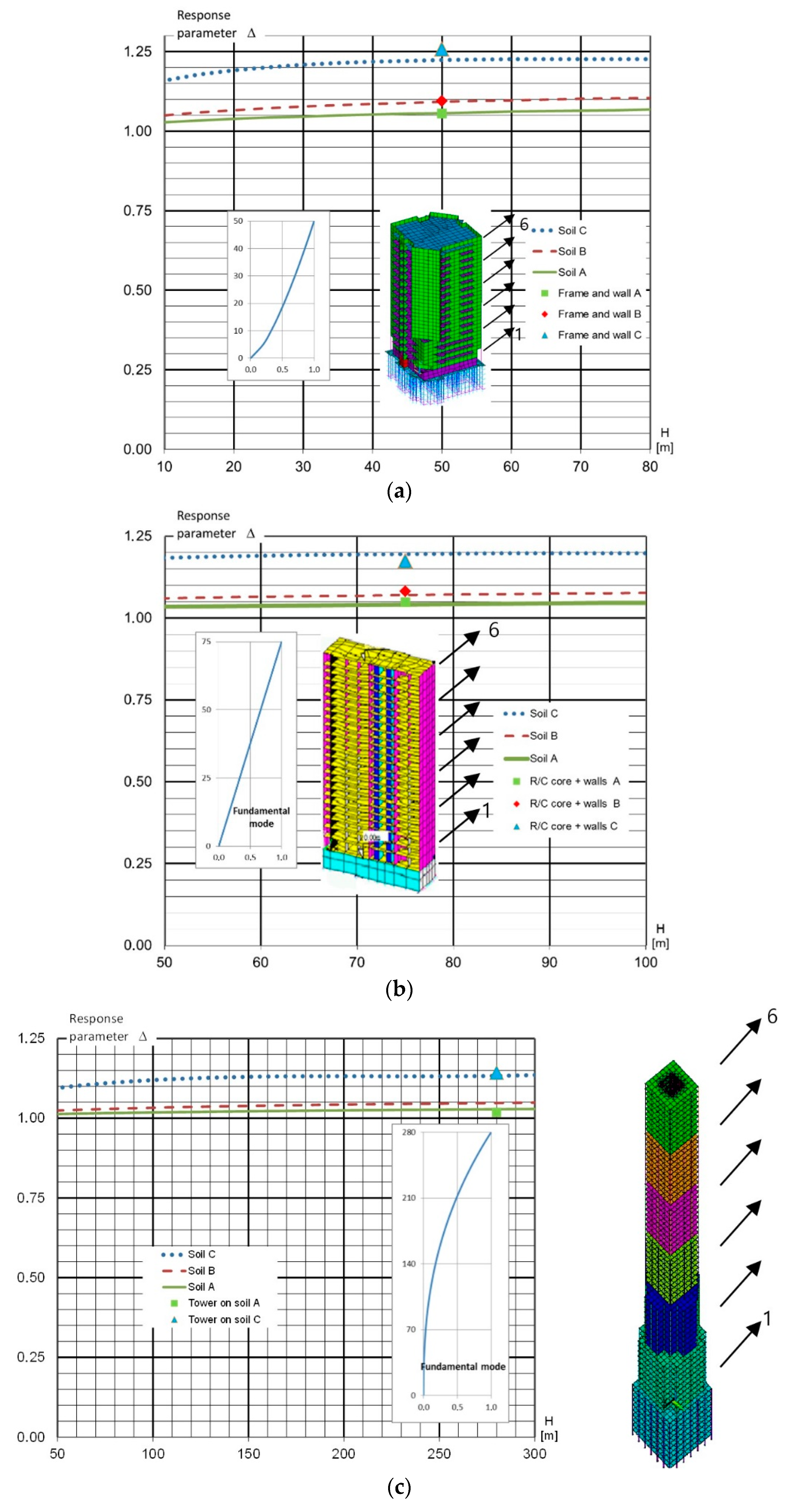
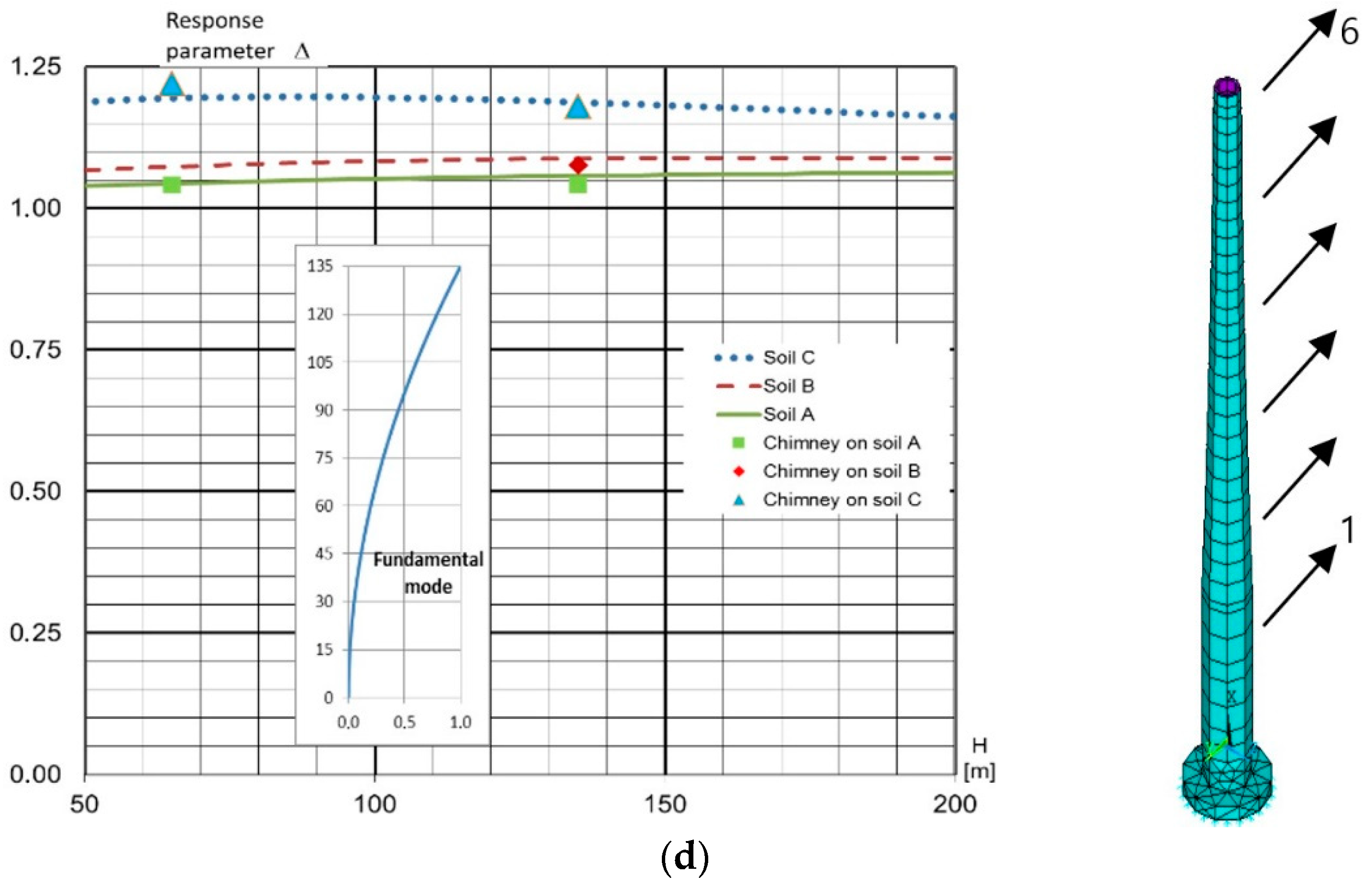
The dependence of the response parameter according to Equation (33) on the total height of the building is depicted in
Figure 2. The effect of soil parameters is also taken into account.
In order to verify these results, detailed analyses of four selected structures located on different soil types are investigated in the next section.
5. Detailed FEM Analyses
The procedure for determining the response parameters, which describe the increase in the rotational seismic components to the overall seismic response according to the previous section, is only an assessment because of its simplicity. Nevertheless, it provides an appropriate quick overview for the designers when a more complex analysis is necessary. This coefficient with a somewhat limited precision can be also used for the estimation of the error of the simplified solution. We decided to verify it on more complex structures.
Four different structural types have been assumed (
Figure 2) and analyzed using FEM ANSYS software: (a) frame + wall (
), (b) R/C core building with perimeter columns (
), (c) tower (
) and finally a special structure, (d) chimney. The last one is with two different heights,
and
.
The well-known formula Eq. (19) has been assumed with a structural coefficient = 0.03; 0.043; 0.085; 0.045 for the (a) frame + wall, (b) R/C core with perimeter columns; (c) tower and (d) chimney, respectively, according to [
26,
27], cl.4.3.3.2.2(3), respectively.
Due to the diversity of structural systems, it was necessary to choose a suitable comparative quantity. As a comparative quantity expressing the seismic effects in a simplified way, a fictitious bending moment at the fixed end calculated from the amplitudes of inertial forces according to Equation (35) was used. This variable was an appropriate benchmark for a mutual comparison of results in accordance with
Section 3 and
Section 4.
The procedure was as follows:
- (a)
Work has started with a complex 3D FEM model (
Figure 2), taking into account all relevant constructional details, including different types of foundation. In case (a), it was piles; in case (b), a foundation slab and two underground floors; in case (c), diaphragm walls; in case (d), a circular foundation slab. For these structures, the natural frequencies and the mode shapes have been calculated, from which the first two bending mode shapes in a given direction were selected (see the arrows of
Figure 2), which have to match the calculations of steps (b), (c).
- (b)
For each structure, we have prepared a simplified alternate dynamic model with six degrees of freedom representing the horizontal displacements in the considered direction of the vibrations (
Figure 2). The flexibility matrix of the simplified model was calculated using unit forces acting in places of the six degrees of freedom on the complex model
where
are the displacements of the selected six degrees of freedom, evenly distributed along the height of the building (as in
Figure 1a) in the direction
from the unit force applied in the direction
. From the flexibility matrix, the stiffness matrix
was calculated. The mass matrix was calculated as a diagonal matrix with concentrated masses (lumped mass matrix) attributable to the six degrees of freedom.
- (c)
The first two bending eigenfrequencies and mode shapes were calculated on the simplified model according to (b), and these were compared with the calculated frequencies from the complex model of (a). Since this is a linear calculation, the first two bending eigenfrequencies and mode shapes matched well. Further the following was made:
- (c1)
Calculation of the standard seismic response
with consideration of only the translational components of the seismic excitation to calculate the amplitudes of the inertial forces (Equation (5)) at the six points along the height of the building (
Table 2);
- (c2)
Calculation of the expanded seismic response considering the rotational components of ground motion (Equation (13)) combined with the standard actions of according to (c1).
The seismic effects were replaced by amplitudes of the quasi-static inertial forces, calculated in the case (c1) according to Equation (5). In the case (c2), a combination of the effects of forces according to Equation (5) and the effects of additional forces caused by the rotational components of ground motion according Equation (13) was calculated.
From these forces, fictitious bending moments in the fixed end were calculated as the resulting seismic effects for comparison purposes. For the case (c1)
and for the case (c2)
- (d)
Finally, the ratio of the response parameter was calculated from Equation (2)
Figure 2 shows the influence of the response parameter
for different structural types. The results of these complex calculations represent always only certain points identifiable by the height of the building
. The above results show that the variables correspond with the curves for each type of construction and various soil conditions with sufficient accuracy. In
Figure 2, the basic shape of the bending vibration is also displayed next to the scheme of the building or the chimney.
In case (a), a frame + wall structural system is assumed. The pile foundations have been modeled too. The soil–structure interaction was simply assumed by Winkler’s springs applied on the piles in both horizontal directions and on the foundation deck in vertical direction. Small irregularity in the plan has been considered. The total height of the building is 50 m. Three different soil categories (A, B and C) have been assumed. Both translational and rotational seismic inputs have been analyzed according to Eurocode 8, Part 6. It is easy to see that the results of the ratio of the total rocking moments (translational and rotational input) to the rocking moment, assuming translational input only, match well with the estimation factor for a height of 50 m. There is a small difference in the soil C result where estimation of reaches the value 1.23 and the value from SRSS analyses is 1.26.
In case (c), the core structural system is assumed as a tall building with a total height of 280 m. In this case, a building with more irregularity in height is assumed. It is easy to see that the results of the ratio between the total rocking moments (translational and rotational input) to the rocking moment, assuming translational input only, match quite well with the estimation factor for height 280 m, especially for soil C.
The study of irregularity in the plan and height needs to be analyzed in more detail in the future.
It can be also stated from the analyses summarized in
Figure 2 that the influence of the rotational component mainly depends on the soil category for tall buildings.
6. Conclusions
As we can see in
Figure 2, the simplified analyses according to
Section 3 provide quite satisfactory results. The corresponding values from more complex analyses for four selected types of structures (
Section 5) are close to the curves obtained from simplified analyses.
The increase in overall seismic design effects, calculated as a fictitious bending moment at the basement level, caused by horizontal inertial forces due to rotational components of seismic effects, increase the overall seismic response by not more than 10%, even for very high buildings about 250 m tall. This statement is valid only if the buildings are constructed at the site with soil classes A and B. In the case of less stiff soil, e.g., soil category C or worse, the contribution of rotational components is more important and very quickly reaches the value up to 20–25% even for relatively low buildings such as those in case (a).
The simplified analysis introduced in
Section 3 is appropriate for making decisions about whether the rotational components of the seismic effects can be neglected or whether they are so important that they have to be taken into account.
It seems that the soil category is an equally important governing parameter as the height of the building in the decision whether to prescribe the designers to consider also the rotational components of seismic movement or not. This study should serve for a future discussion on how to improve the code and it can help the designers in the phase of preparing the necessary types of analyses.
Author Contributions
Conceptualization, M.S. and R.Á.; methodology, M.S.; software, M.S. and M.M.; validation, K.L., M.M. and J.G.-S.-C.; formal analysis, R.A., J.G.-S.-C.; investigation, R.Á.; resources, R.Á., J.G.-S.-C.; data curation, M.S. and R.Á.; writing—original draft preparation M.S. and R.A.; writing—review and editing J.G.-S.-C., K.L.; visualization, K.L.; supervision, R.Á. and M.S; project administration, M.S. and R.Á. All authors have read and agreed to the published version of the manuscript.
Funding
This research has been supported by the grant nos. 1/0749/19 and 1/0773/18 provided by the VEGA Agency of Ministry of Education, Science, Research and Sport of the Slovak Republic.
Institutional Review Board Statement
Not applicable.
Informed Consent Statement
Not applicable.
Data Availability Statement
The data presented in this study are available on request from the corresponding author.
Conflicts of Interest
The authors declare no conflict of interest.
References
- Igel, H.; Brokesova, J.; Evans, J.; Zembaty, Z. Preface to the special issue on “Advances in rotational seismology: Instrumentation, theory, observations, and engineering”. J. Seismol. 2012, 16, 571–572. [Google Scholar] [CrossRef]
- Harichandran, R.S.; Vanmarcke, E.H. Stochastic variation of earthquake ground motion in space and time. J. Eng. Mech. ASCE 1986, 112, 154–174. [Google Scholar] [CrossRef]
- Lee, V.W.; Trifunac, M.D. Torsional accelerograms. Soil Dyn. Earthq. Eng. 1985, 4, 132–139. [Google Scholar] [CrossRef]
- Lee, V.W.; Trifunac, M.D. Empirical scaling of rotational spectra of strong earthquake ground motion. Bull. Seismol. Soc. Am. 2009, 99, 1378–1390. [Google Scholar] [CrossRef]
- Lee, W.H.K.; Çelebi, M.; Todorovska, M.I.; Igel, H. Introduction to the special issue on rotational seismology and engineering applications. Bull. Seismol. Soc. Am. 2009, 99, 945–957. [Google Scholar] [CrossRef]
- Loh, C.-H. Spatial variability of seismic waves and its engineering application. Struct. Saf. 1991, 10, 95–111. [Google Scholar] [CrossRef]
- Bonev, Z.; Vaseva, E.; Blagov, D.; Mladencov, K. Seismic design of slender structures including rotational components of the ground acceleration—Eurocode 8 approach. In Proceedings of the 14th European Conference on Earthquake Engineering ECEE, Ohrid, Macedonia, 30 August–3 September 2010. [Google Scholar]
- Bonev, Z.; Vasilev, G. Seismic design of tall and slender structures including rotational components of the ground motion: EN 1998-6 approach. Bauhaus Summer School 023. Model Validation and Simulation, Graduate Courses for Structural Engineering Applications. Schriftenreihe des Instituts für Konstruktiven Ingenieurbau, Bauhaus-Universität Weimar. August 2012. Available online: https://consteelsoftware.com/wp-content/uploads/2020/09/IKI23_klein.pdf (accessed on 8 January 2021).
- Bońkowski, P.A.; Zembaty, Z.; Minch, M.Y. Time history response analysis of a slender tower under translational-rocking seismic excitations. Eng. Struct. 2018, 155, 387–393. [Google Scholar] [CrossRef]
- Bońkowski, P.A.; Zembaty, Z.; Minch, M.Y. Engineering analysis of strong ground rocking and its effect on tall structures. Soil Dyn. Earthq. Eng. 2019, 116, 358–370. [Google Scholar] [CrossRef]
- Falamarz-Sheikhabadi, M.R.; Ghafory-Ashtiany, M. Approximate formulas for rotational effects in earthquake engineering. J. Seismol. 2012, 16, 815–827. [Google Scholar] [CrossRef]
- Falamarz-Sheikhabadi, M.R.; Ghafory-Ashtiany, M. Rotational components in structural loading. Soil Dyn. Earthq. Eng. 2015, 75, 220–233. [Google Scholar] [CrossRef]
- Zembaty, Z.; Boffi, G. Effect of rotational seismic ground motion on dynamic response of slender towers. Eur. Earthq. Eng. 1994, 8, 3–11. [Google Scholar]
- Zembaty, Z. Rotational seismic load definition in Eurocode 8, Part 6, for slender tower-shaped structures. Bull. Seismol. Soc. Am. 2009, 99, 1483–1485. [Google Scholar] [CrossRef]
- Basu, D.; Whittaker, A.S.; Constantinou, M.C. Estimating rotational components of ground motion using data recorded at a single station. J. Eng. Mech. ASCE 2012, 138, 1141–1156. [Google Scholar] [CrossRef]
- Basu, D.; Whittaker, A.S.; Constantinou, M.C. Extracting rotational components of earthquake ground motion using data recorded at multiple stations. Earthq. Eng. Struct. Dyn. 2013, 42, 451–468. [Google Scholar] [CrossRef]
- Li, H.N.; Sun, L.Y.; Wang, S.Y. Improved approach for obtaining rotational components of seismic motion. Nucl. Eng. Des. 2004, 232, 131–137. [Google Scholar] [CrossRef]
- Kalkan, E.; Graizer, V. Coupled Tilt and Translational Ground Motion Response Spectra. J. Struct. Eng. 2007, 133, 609–619. [Google Scholar] [CrossRef]
- Zembaty, Z.; Bernauer, F.; Igel, H.; Schreiber, U. (Eds.) Special Issue “Rotation Rate Sensors and Their Applications”. Sensors 2020, 20, 6930, ISSN 1424-8220. [Google Scholar]
- EN 1998-6, Eurocode 8—Design of Structures for Earthquake Resistance—Part 6: Towers, Masts and Chimneys; CEN: Brussels, Belgium, 2005.
- STN EN 1998-6/NA, Eurocode 8—Design of Structures for Earthquake Resistance—Part 6: Towers, Masts and Chimneys—National Annex; SÚTN: Bratislava, Slovakia, 2011.
- Chiauzzi, L.; Masi, A.; Mucciarelli, M.; Cassidy, J.F.; Kutyn, K.; Traber, J.; Ventura, C.; Yao, F. Estimate of fundamental period of reinforced concrete buildings: Code provisions vs. experimental measures in Victoria and Vancouver (BC, Canada). In Proceedings of the 15th World Conference on Earthquake Engineering 2012 (15WCEE), Lisbon, Portugal, 24–28 September 2012. [Google Scholar]
- Goel Rakesh, K.; Chopra Anil, K. Period formulas for moment-resisting frame buildings. J. Struct. Eng. ASCE 1997, 123, 1454–1461. [Google Scholar] [CrossRef]
- Salama Magdy, I. Estimation of period of vibration for concrete moment-resisting frame buildings. Hous. Build. Natl. Res. Cent. HBRC J. 2015, 11, 16–21. [Google Scholar] [CrossRef][Green Version]
- Shea, G.H. SEAOC Blue Book, Recommended Lateral Force Requirements and Commentary, 7th ed.; Seismology Committee Structural Engineers Association of California: Sacramento, CA, USA, 1999. [Google Scholar]
- EN 1998-1, Eurocode 8—Design of Structures for Earthquake Resistance—Part 1: General Rules, Seismic Actions and Rules for Buildings; CEN: Brussels, Belgium, 2004.
- STN EN 1998-1/NA, Eurocode 8—Design of Structures for Earthquake Resistance—Part 1: General Rules, Seismic Actions and Rules for Buildings, National Annex; SÚTN: Bratislava, Slovakia, 2009.
- EN 1991-1-4, Eurocode 1—Actions on Structures—Part 1-4: General Actions—Wind Actions; CEN: Brussels, Belgium, 2005.
- Whitman, R.V.; Richart, F.E. Design Procedures for Dynamically Loaded Foundations; IP-766; Industry program of the College of Engineering, The University of Michigan: Ann Arbor, MI, USA, 1967; Available online: https://deepblue.lib.umich.edu/bitstream/handle/2027.42/8273/bad6985.0001.001.pdf?sequence=5 (accessed on 8 January 2021).
| Publisher’s Note: MDPI stays neutral with regard to jurisdictional claims in published maps and institutional affiliations. |
© 2021 by the authors. Licensee MDPI, Basel, Switzerland. This article is an open access article distributed under the terms and conditions of the Creative Commons Attribution (CC BY) license (http://creativecommons.org/licenses/by/4.0/).

 ,
, 


