A Method of Two-Stage Pressure Control Based on Multistage Orifices
Abstract
:Featured Application
Abstract
1. Introduction
2. Theoretical Analysis
- (1)
- If the diameters of orifices connected in series are equal, the pressure-drop value of each orifice is also equal.
- (2)
- If the diameter difference between the orifices in series is large and satisfies prerequisites d1 ≥ 2d2, d2 = d3, the pressure drop of the orifice with the largest diameter is very small.
3. Engineering Implementation of Two-Stage Pressure-Control Method
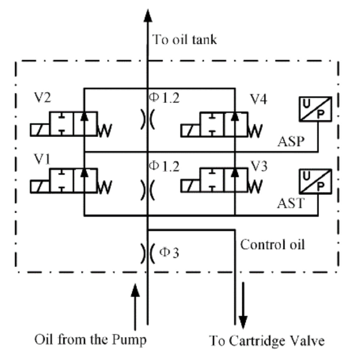
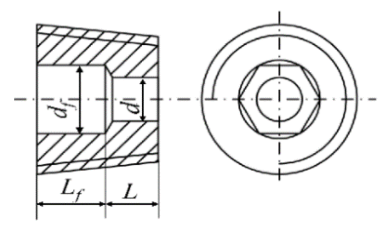
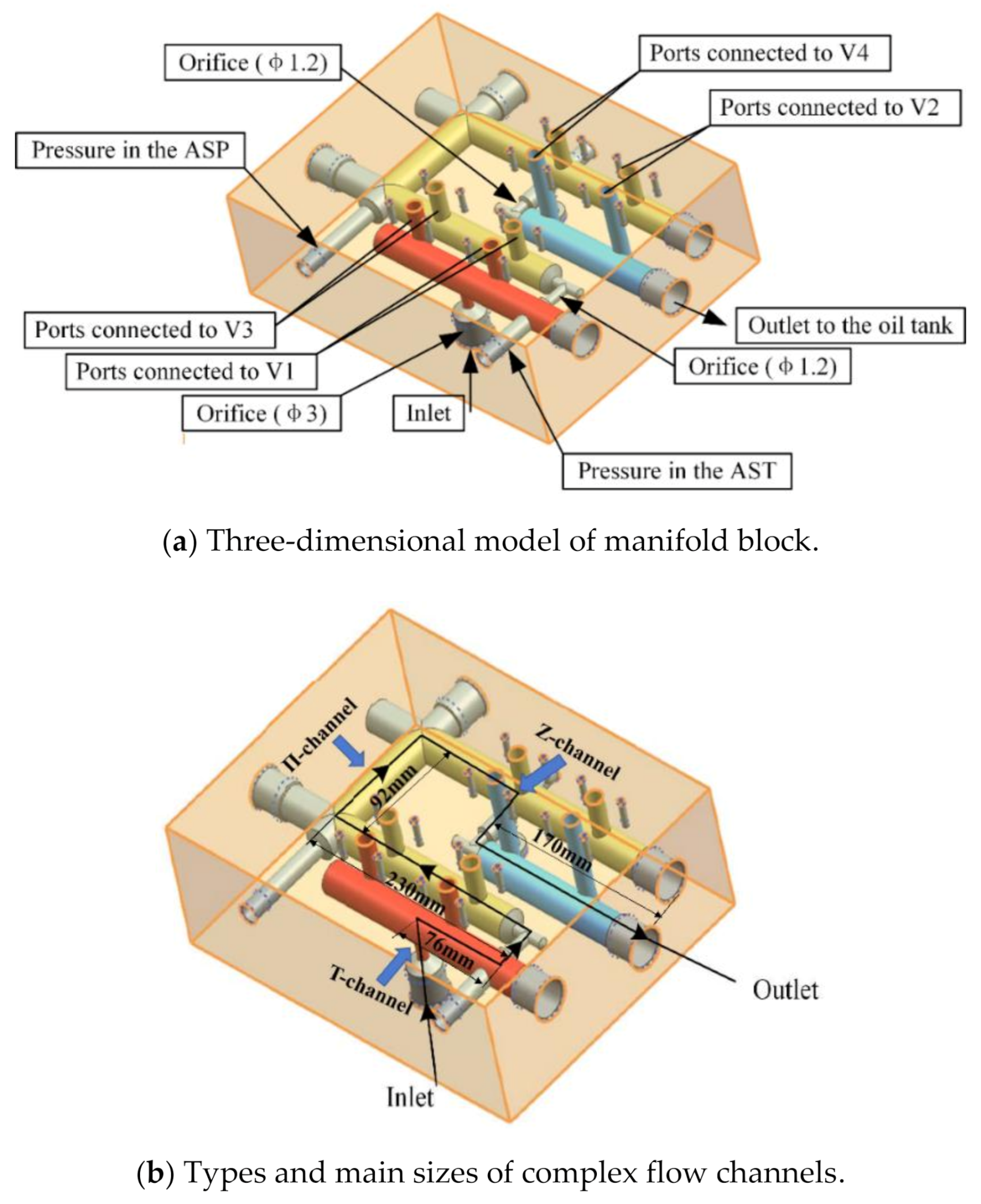
3.1. Implementation Principle of Engineering Scheme
3.2. Reliability Analysis of Pilot Pressure Control
- (1)
- The abnormal working state of the directional valve can be forewarned according to the pressure value of Pasp when three orifices are in series. If pressure Pasp suddenly rises, the electromagnet of the solenoid valve V1 or V3 is in the power-off state, and the second orifice is “short-circuited” (as shown in Figure 2b). If pressure Pasp suddenly drops, the electromagnet of solenoid valve V2 or V4 is in the power-off state, and the third orifice is “short-circuited” (as shown in Figure 2c).
- (2)
- The scheme that two orifices are connected in series to realize high control pressure has no warning function.
4. Test Verification and Engineering Application
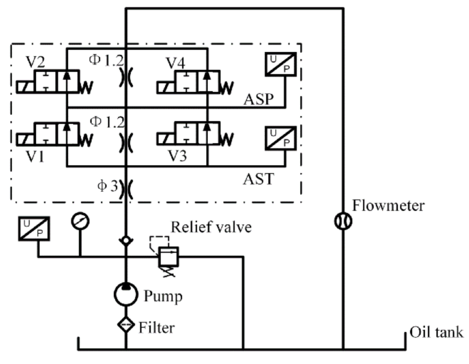
4.1. Test Verification
4.2. Application in Turbine Electrohydraulic Control System
5. Results and Discussion
5.1. Pilot Control Pressure
5.2. Reliability Verification of Pilot Pressure Control
6. Conclusions
Author Contributions
Funding
Institutional Review Board Statement
Informed Consent Statement
Data Availability Statement
Conflicts of Interest
References
- Cioncolini, A.; Cassineri, S.; Duff, J.; Curioni, M.; Scenini, F. Micro-orifice single-phase flow at very high Reynolds number. Exp. Therm. Fluid Sci. 2018, 91, 35–40. [Google Scholar] [CrossRef]
- Peng, J.; Youn, C.; Takeuchi, T.; Kagawa, T. Stabilization of pilot valve system using linear flow resistance. Adv. Mech. Eng. 2017, 9, 1687814017719421. [Google Scholar] [CrossRef]
- Kiaoulias, D.N.; Travis, T.A.; Moore, J.D.; Risha, G.A. Evaluation of orifice inlet geometries on single liquid injectors through coldflow experiments. Exp. Therm. Fluid Sci. 2019, 103, 78–88. [Google Scholar] [CrossRef]
- Hu, Y.P.; Peng, Y.D.; Wu, G.M. Hydraulic Resistance Network Systems; Machinery Industry Press: Beijing, China, 2002. [Google Scholar]
- Araoye, A.A.; Badr, H.M.; Ahmed, W.H. Investigation of flow through multistage restricting orifices. Ann. Nucl. Energy 2017, 104, 75–90. [Google Scholar] [CrossRef]
- Haimin, W.; Shujuan, X.; Qingyi, S.; Caimin, Z.; Hao, L.; Eryun, C. Experiment study on pressure drop of a multistage letdown orifice tube. Nucl. Eng. Des. 2013, 265, 633–638. [Google Scholar] [CrossRef]
- Ju, D.; Huang, Z.; Jia, X.; Qiao, X.; Xiao, J.; Huang, Z. Macroscopic characteristics and internal flow pattern of dimethyl ether flash-boiling spray discharged through a vertical twin-orifice injector. Energy 2016, 114, 1240–1250. [Google Scholar] [CrossRef]
- Luo, Y.L.; Wang, Q.; Zhang, M.L. Study on damping characteristics of flow control circuit of bypass pressure compensation valve. Chin. J. Mach. Tool Hydraul. 2018, 46, 31–34. [Google Scholar]
- Shuichi, T.; Yang, W.J. Thermal-fluid transport phenomena in an axially rotating flow passsge with twin concentric orifices of different radii. Int. J. Energy Res. 2005, 12, 331–342. [Google Scholar]
- Lichtarowicz, A.; Duggins, R.K.; Markland, E. Discharge coefficients for incompressible non-cavitating flow through long orifices. J. Mech. Eng. Sci. 1965, 7, 210–219. [Google Scholar] [CrossRef]
- Schrank, K.; Murrenhoff, H. CFD Simulations and Experiments of the Dispersed Two-phase Flow through Hydraulic Orifices. In Proceedings of the ASME 2013 Fluids Engineering Division Summer Meeting, Incline Village, NV, USA, 7–11 July 2013; pp. 1–8. [Google Scholar]
- Gao, J.X.; Wu, F.H. Investigation of flow through the two-stage orifice. Eng. Appl. Comput. Fluid Mech. 2019, 13, 117–127. [Google Scholar] [CrossRef] [Green Version]
- Silvaa, E.A.A.; Ochoa, A.A.V.; Henríquez, J.R. Analysis and runners length optimization of the intake manifold of a 4-cylinder spark ignition engine. Energy Convers. Manag. 2019, 188, 310–320. [Google Scholar] [CrossRef]
- Gu, P.; Hashemian, M.; Sosale, S.; Rivin, E. An Integrated Modular Design Methodology for Life-Cycle Engineering. CIRP Ann. 1997, 46, 71–74. [Google Scholar] [CrossRef]
- Yamada, T.; Hasegawa, S.; Kinoshita, Y.; Yamada, S.; Inoue, M.; Rosebrock, C.; Bracke, S. Process integration concept for waste reduction among manufacturing planning, modularization and validation. Procedia Manuf. 2018, 21, 337–344. [Google Scholar] [CrossRef]
- Huang, R.H. Based on MINISO Compact Two-way Cartridge Valves, a New Generation of Modular, with the Group and Open Electric-Hydraulic Control Technology Combined. Hydraul. Pneum. Seals 2012, 1, 78–81. [Google Scholar]
- Hu, J.J.; Chen, J.; Quan, L.X.; Zhang, J.; Kong, X.D. Turbulence Model Correction and Internal Flow Characteristics Analysis of Hydraulic Manifold Blocks. Chin. J. Mech. Eng. 2017, 28, 1708–1713. [Google Scholar]
- Gao, X.P.; Zhang, H.; Liu, J.J.; Sun, B.W.; Tian, Y. Numerical investigation of flow in a vertical pipe inlet/outlet with a horizontal anti-vortex plate: Effect of diversion orifices height and divergence angle. Eng. Appl. Comput. Fluid Mech. 2017, 12, 182–194. [Google Scholar] [CrossRef]
- Grabe, C.V.; Riedel, C.; Stammen, C.; Murrenhoff, H. An Analytic Thermodynamic Model for Hydraulic Resistances Based on CFD Flow Parameters. Int. J. Fluid Power 2013, 14, 17–26. [Google Scholar] [CrossRef]
- Mohan, K.H.M.; Yogesh, K.K.J.; Seshadri, V. CFD Analysis of Flow through Dual Orifice Plate Assembly. Int. J. Emerg. Technol. Adv. Eng. 2015, 5, 136–144. [Google Scholar]
- Rito, G.D. Experiments and CFD Simulations for the Characterisation of the Orifice Flow in a Four-Way Servovalve. Int. J. Fluid Power 2007, 8, 37–46. [Google Scholar] [CrossRef]
- Shah, M.S.; Joshi, J.B.; Kalsi, A.S.; Prasad, C.S.R.; Shukla, D.S. Analysis of flow through an orifice meter: CFD simulation. Chem. Eng. Sci. 2012, 71, 300–309. [Google Scholar] [CrossRef]
- Singh, V.K.; Tharakan, T.J. Numerical Simulations for Multi-hole Orifice Flow Meter. Flow Meas. Instrum. 2015, 45, 375–383. [Google Scholar] [CrossRef]
- Cao, Y.N.; Tian, S.J.; Wang, Y.A.; Zhang, H. HMB Duct Nets’ Dynamic Characteristic Simulation Based on Typical Flow-resistance. J. Syst. Simul. 2009, 21, 3460–3463. [Google Scholar]
- Xie, G.Q.; Li, Y.C. Simulation and Analysis for Flow Field of Typical Channel Inside Hydraulic Manifold Block Based on Fluent. Chin. J. Hydr. Pneum. 2013, 12, 44–47. [Google Scholar]
- Backe, W. Hydraulic Resistance Loop Systems; Machinery Industry Press: Beijing, China, 1980. [Google Scholar]
- Tamburrano, P.; Plummer, A.R.; Distaso, E.; Amirante, R. A review of electro-hydraulic servovalve research and development. Int. J. Fluid Power 2019, 20, 53–98. [Google Scholar] [CrossRef]
- Merritt, H. Hydraulic Control System; John Wiley and Sons: New York, NY, USA; London, UK; Sydney, Australia, 1967. [Google Scholar]
- Johansen, F.C. Flow through Pipe Orifices at Low Reynolds Numbers. Proc. R. Soc. A 1930, 126, 231–245. [Google Scholar]
- Sheng, J.C. Hydraulic Fluid Dynamics; Machinery Industry Press: Beijing, China, 1982. [Google Scholar]
- Shan, F.; Fujishiro, A.; Tsuneyoshi, T.; Tsuji, Y. Particle image velocimetry measurements of flow field behind a circular square-edged orifice in a round pipe. Int. J. Heat Mass Transf. 2013, 73, 542–550. [Google Scholar] [CrossRef]
- Modi, P.P.; Jayanti, S. Pressure losses and flow maldistribution in ducts with share bends. Chem. Eng. Res. Des. 2004, 82, 321–331. [Google Scholar] [CrossRef]


| d 1 | df 2 | L | Lf |
|---|---|---|---|
| 3 | 4.7 | 3.5 | 4.5 |
| 1.2 | 4.7 | 3.5 | 4.5 |
| Conclusion | Normal | V1 or V3 Abnormal | V2 or V4 Abnormal | |
|---|---|---|---|---|
| Pressure | ||||
| Past | 0.98Ps | 0.975Ps | 0.975Ps | |
| Pasp | 0.49Ps | 0.975Ps | 0 | |
| Conclusion | Solenoid Valve | Oil Block | Theoretical Value | |
|---|---|---|---|---|
| Pressure | ||||
| Past (bar) | 1.4 | 0.3 | 0 | |
| Pasp (bar) | 0.7 | 0.3 | 0 | |
| Conclusion | Normal | V1 or V3 Abnormal | V2 or V4 Abnormal | |
|---|---|---|---|---|
| Pressure | ||||
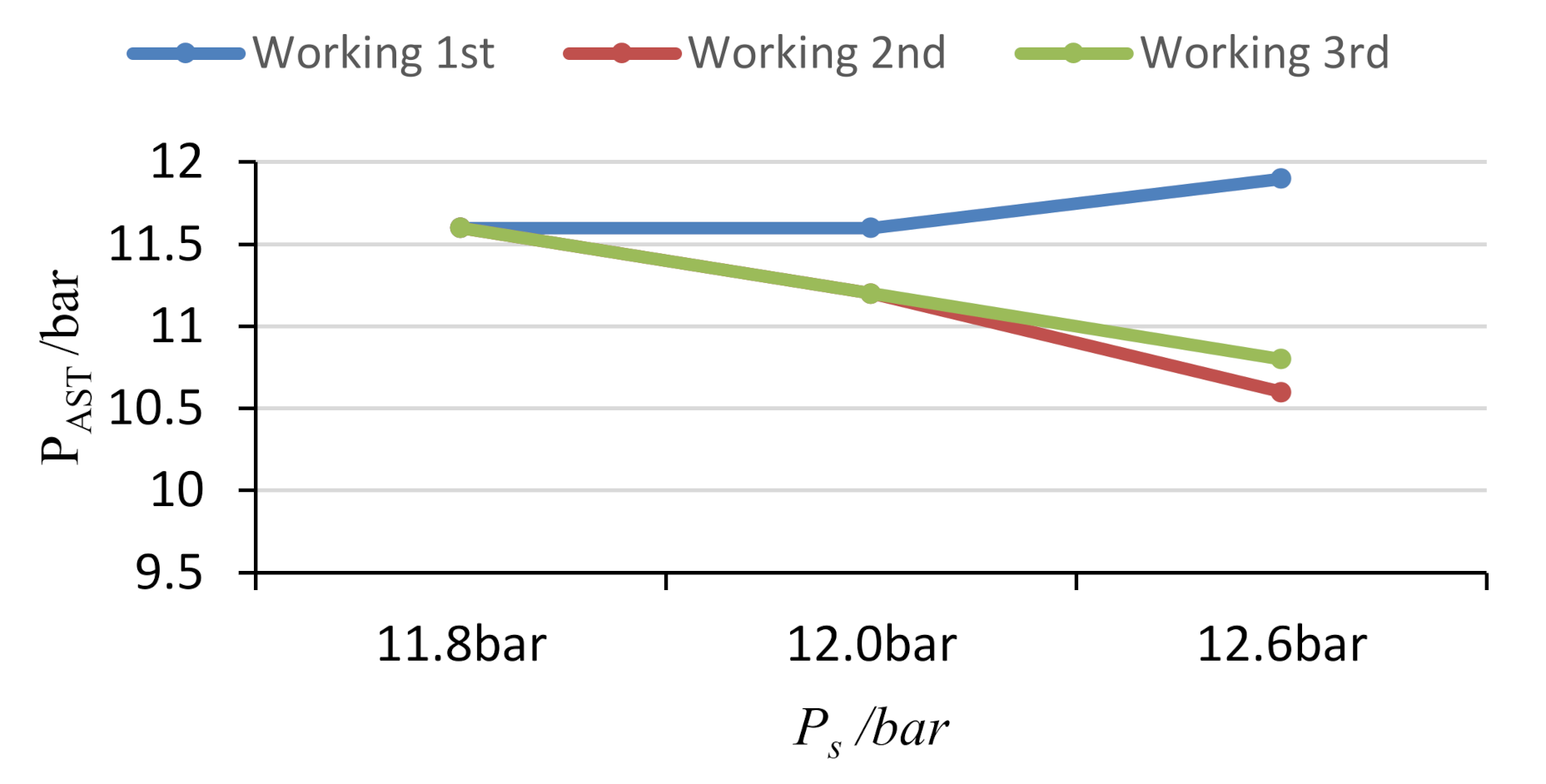
| Past (bar) | 11.6 | 11.2 | 11.2 | |
| Pasp (bar) | 5.3 | 10.5 | 0.6 | |
Publisher’s Note: MDPI stays neutral with regard to jurisdictional claims in published maps and institutional affiliations. |
© 2021 by the authors. Licensee MDPI, Basel, Switzerland. This article is an open access article distributed under the terms and conditions of the Creative Commons Attribution (CC BY) license (http://creativecommons.org/licenses/by/4.0/).
Share and Cite
Gao, J.; Wu, F.; Tang, J.; Geng, Z. A Method of Two-Stage Pressure Control Based on Multistage Orifices. Appl. Sci. 2021, 11, 589. https://doi.org/10.3390/app11020589
Gao J, Wu F, Tang J, Geng Z. A Method of Two-Stage Pressure Control Based on Multistage Orifices. Applied Sciences. 2021; 11(2):589. https://doi.org/10.3390/app11020589
Chicago/Turabian StyleGao, Junxia, Fenghe Wu, Jun Tang, and Zichun Geng. 2021. "A Method of Two-Stage Pressure Control Based on Multistage Orifices" Applied Sciences 11, no. 2: 589. https://doi.org/10.3390/app11020589
APA StyleGao, J., Wu, F., Tang, J., & Geng, Z. (2021). A Method of Two-Stage Pressure Control Based on Multistage Orifices. Applied Sciences, 11(2), 589. https://doi.org/10.3390/app11020589


