Abstract
The numerical simulation and analysis of the ejection of an ink droplet through a nozzle as well its motion through air until its contact with a surface and taking up of a stable form is performed. The fluid flow is modeled by the incompressible Navier–Stokes equations with added surface tension. The presented model can be solved using either a level set or a phase field method to track the fluid interface. Here, the level set method is used to determinate the interface between ink and air. The presented work concentrates on the demonstration how to check the suitability of ink for inkjet printhead nozzles, for instance, for the use in printers. The results such as velocity, change of size, and volume dependence on time of an ink droplet are presented. Recommendations for the use of specific inks are also given.
1. Introduction
Nowadays, inkjet printing has become relevant besides application for brochures, flyers, and other paper-based products, also in areas such as shirt printing or personalized production while thereby satisfying increasing quality demands. In this way, inkjet printing is continuously enhancing its capabilities. According to Smithers Pira’s [1] report, the inkjet printing market will grow at least till 2023, both by deepening its penetration into existing markets, and exploiting new emergent market opportunities. In doing so, there are three main markets where inkjet technology will increase in relevance: book printing, commercial printing, and packaging printing. With the printing market is expected to grow, there are many propositions to improve the productivity of inkjet processes. Nowadays, inkjet printing is worldly used in many manufacturing applications. It shows the same quality and speed as many other traditional printing methods such as flexography or lithography (Castrejon-Pita et al. [2]).
Of relevance for inkjet printing is the drop-on-demand (DOD) inkjet technology. DOD technology is to eject small droplets of ink from a printing head nozzle onto a substrate only when required to form the image. Drops are generated by quick pressure increase inside a nozzle to eject the ink. The most popular technology to increase pressure is to use a piezoelectric element in every nozzle chamber. When a voltage is applied to the actuator, the piezoelectric element changes its shape to displace the chamber wall or roof into the chamber to generate the required pressure for the drop ejection, Hoath [3]. The main advantage in inkjet printing is the possibility to deposit different sized droplets one by one on many different materials with predetermined locations on the substrate without any contact. To perfectly fulfill its demand, inkjet printing is required to produce small quantity prints with low cost and high-resolution quality at tolerable requirements. Every year, inkjet printing is increasing in popularity and progressing in different using areas.
Inkjet printing technology has been extensively used due to its advantages regarding flexible droplet formation. There are various areas where inkjet technologies can be applied. As a consequence, there are many investigations on inkjet printing addressing things such as nozzle configurations (parameters), different jetting velocities, droplet sizes, and frequency of jets (Stringer and Derby [4], Wijshoff [5], Bos et al. [6]). Inkjet technology also can be adjusted by making microlenses for optical devices, Yuzo et al. [7]. Furthermore, inkjet technology can be used as a manufacturing technique for producing ceramic parts (Ainsley et al. [8]) or making collagen scaffolds (biomaterials) with a predefined internal morphology, Sachlos et al. [9].
It is found that a nozzle configuration affects droplet shape and velocity which is beneficial for the enhanced printing quality and high-throughput printing rate, Aqeel et al. [10].
In case of ink-jet printing technology which is non-contacting, material can be printed layer-on-layer to configure 3-D structures. This capability enabled the first use of ink-jet printing to build active microelectromechanical systems (MEMS), Fuller [11]. Despite such progress, for the moment, there are not many works to define how ink will perform over its lifetime and how ink structure changes over time. Such experiments are in progress at different universities and research institutes, Korvink et al. [12]. Nonetheless, the so far performed research places inkjet technology as the key focus for technology developers.
In the past, DOD printhead nozzle droplet ejection and the settling process were investigated with regard to the printing quality. The ability of modeling the jetting process and droplet settling parameters is important as it can be used as a tool for future ink and printing device developments. In the past, much research addressing the inkjet printing process was done by slow motion cameras (Martin, et al. [13]). Thereby pictures are examined, and droplet parameters can be calculated from 2D views. In addition, it is possible to address droplet motion by numerical simulations, Wu et al. [14]. Many authors (Bos et al. [6], Tan et al. [15]) have conducted research to compare differences between numerical simulations and slow motion camera observations. Obtained results are in agreement and based on the numerical simulations performed, of which we can base our inkjet droplet model.
It should be noted the current state of art, which may be related to the work presented here. Various ways of implementation of DOD technology and related investigations can be found in scientific literature. The development of drop-on-demand electrohydrodynamic jet (DoD E-Jet) printing to enhance print control and to achieve stable micro-structures on a flexible insulating substrate were analyzed by Abbas et al. [16]. The theoretical design of the inkjet process to improve delivery efficiency was investigated by comparing numerical investigations and physical experiments by Zhong et al. [17]. A high temperature drop-on-demand droplet generator for metallic melts was analyzed by Imani Moqadam et al. [18]. Microstructure adjustment of spherical micro-samples for high-throughput analysis using a drop-on-demand droplet generator were also analyzed by the latter authors [19]. Electro-hydrodynamic drop-on-demand printing of aqueous suspensions of drug nanoparticles were introduced by Elele et al. [20]. The effect of meniscus damping ratio on drop-on-demand electrohydrodynamic jetting was analyzed by Kim et al. [21].
The analysis of droplet motion is still relevant. A one-dimensional model for the droplet ejection process in inkjet devices was introduced by Jiang and Tan [22]. They showed that a 1D model can significantly reduce the computational time (usually less than one minute) yet with acceptable accuracy. The calculation of the critical point regarding the distribution of the droplets generated by various materials in the dimensionless plane considering piezoelectric print-heads (PPHs) were investigated by Wang et al. [23]. Ejection state prediction for a pneumatic micro-droplet generator by backpropagation (BP) neural networks was analyzed by Wang et al. [24]. The simulation and validation of the droplet generation process for revealing three design constraints in electrohydrodynamic jet printing is given by Pan and Zeng [25]. Printed strain sensors based on an intermittent conductive pattern filled with resistive ink droplets were presented by Zymelka et al. [26]. Dynamics of electrowetting droplet motion in digital microfluidic systems was analyzed by Cui et al. [27].
The use of “Jet” technologies offers a variety of technical implementation options. A theoretical model for an electrostatic lens that is incorporated into an e-jet system to shape the electric field inside the printhead was introduced by Liu and Huang [28]. Controlling the voltage applied to electrodes located around the jet, its trajectory can be continuously adjusted by lateral accelerations which was investigated by Liashenko et al. [29]. Aerosol-jet printed nanocomposites for flexible and stretchable thermoelectric generators were analyzed by Ou [30]. A model and calculations referring to the shear rate of ink in an inkjet printer nozzle were given by Dybowska-Sarapuk et al. [31]. A review of the issues that come along with preparing and printing carbon nanotube ink was given by Tortorich et al. [32]. Inkjet printing of drug-loaded mesoporous silica nanoparticles was analyzed by Wickström et al. [33]. They suggest that inkjet printing technology could function as a flexible deposition method of pharmaceutical suspensions.
The printing can be applied even for biological structures. Mechanical properties of 3D-printed blood vessels were analyzed by Wang et al. [34]. Drop-on-demand (DOD) 3D bioprinting technology was introduced by Grottkau et al. [35].
Based on the good agreement of numerical and experimental investigations regarding the DOD printing process, our droplet simulation model has been developed with the modeling program COMSOL to investigate the different droplet parameters of the DOD printing process. This simulation model can be used to predict the behavior of the droplets in the printing process. The parameters of the droplet ejection, flight, and impact with the substrate will be analyzed to also elaborate on improved printing conditions.
The numerical simulations are initiated using a laminar-two-phase flow function setting and a level set interface. All stages from the main nozzle reservoir where the droplet is forming to the final interaction with the substrate are considered.
With the derived model, it is possible to configure inkjet nozzle properties such as the geometry of the nozzle, the inlet velocity, as well as parameters to study the influence on the size and the speed of the ejected droplet. With the current model, it becomes also possible to investigate how the printing process would perform under changes of the inkjet inks.
2. Problem Formulation
There are many investigations available, focused on drop impact with different surfaces, different jetting parameters, and different Weber and Reynolds numbers (definitions provided later on), Son et al. [36], Bussmann et al. [37]. But there is growing interest on variable fluid drop impact with hydrophobic surfaces in reflecting many practical applications such as printing on polymers.
Researchers are thereby paying close attention to studying the parameters of the nozzle. Many works examine the properties of the nozzle (shape, dimensions, orifice parameters, piezoelectric excitation) that determine the size and velocity of the droplet formed and the circumstances of satellite droplets, Driessen [38]. Satellites are several times smaller droplets than the primary droplet. They can appear if unsuited parameters of ejection or unsuited inks are used. For high-quality printing, they should not appear.
The aim of this work is to provide a numerical model that can help evaluate the shape-changing droplet motion, various initial parameters, and effects/causes influencing this motion, which is an important key component in the inkjet process needed to predict difficult moments or even issues at an early state of the ink developing process. The typical process of DOD droplet formation consists of several stages. This study examines the vertical fall/movement of a droplet formed at the inkjet printing nozzle in air onto a substrate while changing its shape (Figure 1). Droplet status is changing at different instances in time, which are represented by the considered points from A through F. These basic points help to define how a droplet forms and how parameters change over time.
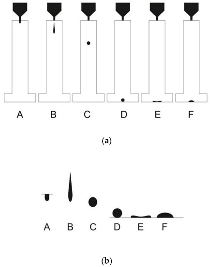
Figure 1.
Droplet fall/movement. (a) During the inkjet printing processes, the droplet is ejected from the inkjet nozzle and settles while changing its shape at different stages (A–F); (b) Highlighted inkjet droplet phases at different stages (A–F). Phases from the left: A—ejection and formation of the droplet; B—droplet pinch off from the nozzle; C—droplet sphere forming; D—droplet before the interaction with the surface; E—droplet spreading at the surface; F—droplet in final stable form.
At point A, the ejection and formation of the droplet comes along with the maximum droplet velocity, then pressure inside the nozzle reaches its maximum and the droplet is ejected from the nozzle. At point B, the droplet thread is pulled off from the printhead nozzle, at this point the droplet has its maximum length and final droplet mass and volume. Point C represents the droplet at almost spherical form when the droplet is formed. Before point C and D, the droplet does not change shape and loses velocity during its settling. Point D represent the instance where droplet interaction with the surface begins, and view E represents the droplet at maximum diameter while spreading. Final point F represents the droplet while oscillating to its final stable form.
In all six phases, different phenomena occur. It can be noticed that the changing forms of the droplet over time can be better explained by considering different instances in time. In the next sections, the different parameters and time sections will be discussed. An overview of the numerical experiment will be given while an insight into the methods used in the investigation is given along with the final parameters. In this research, a closer look is taken at the droplet shape, size, and volume formation and velocity turnover for three different ink parameters. Droplets are generated to perform particularly a vertical fall/movement in air on the substrate. The droplet formation, movement, and impact are modeled by applying a level set function and the Navier–Stokes equations by the commercial finite element package COMSOL Multiphysics. The modeling as part of COMSOL Multiphysics allows similar to the experimental methods; we have used the plotting of flight path as well as the determination of droplet dimensions, velocity, and mass. Additionally, the drag and gravity forces can be also evaluated.
3. Methodology for the Simulation
To represent the fluid interface and convection with air as part of a laminar two-phase flow, the level set method was considered (Olsson and Kreiss [39], Sun and Beckermann [40]). Inkjet inks are treated as Newtonian fluid. According to COMSOL Module User’s Guide [41], the level set function defines the interface, where represents air and is ink. In a transition layer close to the interface, goes smoothly from 0 to 1. The interface moves together with the fluid velocity, u, at the interplay. The following equation describes the convection of the reinitialized level set function, it thereby describes the interface between the 2 phases, ink and air:
Here, ε is corresponding with the thickness of the transition layer. For this model, ε = hc/2, where hc is the representative mesh size in the area passed by the falling droplet. As default, this interface thickness controlling parameter hc it generated automatically and for the current simulation is set to hc = 2.5 μm.
The parameter γ determines the amount of reinitialization or stabilization of the level set function, Olsson and Kreiss [39]. A suitable value for γ is the maximum magnitude occurring in the velocity field. As default, this reinitialization parameter γ is generated automatically and for the current simulation set to γ = 10 m/s.
Beside defining the fluid interface, the level set function is used to smooth the density and viscosity across the interface. Density and dynamic viscosity depend on the interface coefficient . Thereby changes in density and pressure during the calculations are considered, Olsson and Kreiss [39]. Density can be calculated as follows:
Here, 1 denotes the air density while 2 denotes the ink density. For the numerical simulation, the dynamic viscosity (shear viscosity) μ must be taken into account (3). It describes the relationship between the shear rate and the shear stresses in the fluid. Dynamic viscosity is calculated by:
Here, μ1—is the air viscosity and μ2—is the ink viscosity. The transportation of mass and momentum are described by the incompressible Navier–Stokes equations. Both ink and air can be considered as incompressible if the fluid velocity is small compared to the speed of sound.
We investigate ink and air as fluid whose viscous stresses arise from its flow at every point. The Navier–Stokes equations describe the transfer of mass and impulses to an uncompressible fluid, including surface tension and gravity forces. The ink motion including mass conservation is calculated by the following differential equations (Sohr [42]):
Here, denotes the density, μ is the dynamic viscosity, u represents the fluid velocity, p denotes pressure, and Fst is the surface tension force. To capture the effect of the surface tension, a volume force is added at the phase interface in the computational domain where the phase interface is at present. The force depends on the surface tension coefficient and the curvature of the phase interface.
The surface tension force is computed by:
where n is the unit vector in the normal direction, σ is the surface tension coefficient which varies according to the curve, and δ equals a Dirac delta function that is nonzero only at the fluid interface, is the curvature. The unit vector in the normal direction is given by:
while the delta function is approximated by:
To solve Equations (4) and (5), the adaptive mesh refinement functionality for inkjet nozzle modeling as part of COMSOL Multiphysics [41] is used to locally refine the mesh around the ink and air interface. This functionality will essentially divide the simulation into several time intervals, and locally refine the mesh in the region where the phase interface is present in each interval to increase calculation accuracy.
Applying this, the droplet mass can be calculated by:
There are two dimensionless parameters which characterize droplets: the Reynolds number and the Weber number, Hoath [3]. The Reynolds number Re represents the ratio between inertial and viscous forces in a moving fluid and the Weber number, we commutate on the ratio of the inertia to the surface tension. These dimensionless numbers are defined by:
where d is a length parameter—typically, the diameter of the jet, nozzle, or drop and is the droplet velocity. In this research, the nozzle diameter will be used for calculating Re and We numbers. σ is the surface tension coefficient. The influence of velocity in these two dimensionless numbers can be removed by forming a further number, the Ohnesorge number Oh defined by:
The value of the Ohnesorge number Oh, which reflects only on the physical properties of the liquid and the size scale of the jet or drop, is independent of the driving conditions (which control the velocity). Oh turns out to be closely related to the behavior of a jet emerging from a nozzle and, thus, to the conditions in DOD printing, Derby [43,44]. If the Ohnesorge number is too high (Oh ≥ 1.0), then viscous forces will prevent the separation of a drop, while if it is too low (Oh ≤ 0.1), the jet will form a large number of satellite droplets. Satisfactory performance of a fluid in DOD inkjet printing requires an appropriate combination of physical properties, which will also depend on the droplet size and velocity (through the value of the Reynolds or Weber number).
Some authors use the symbol Z as inversed of the Ohnesorge number, Hoath [3]:
Ink printability is considered to be appropriate for ink jet printing if Z in its original definition is between 1–10. Today’s research shows that this range can be adjusted and there are variations possible as higher numbers than 10 can also show good printing characteristics. In this sense, several exceptions were found and reported to the initial range suggested by Derby [43,44].
Ink parameters of the different inks considered in this investigation were aligned with those of ink manufacturers and are assignable to the good printability range (Magdassi [45]). Considered digital ink parameters in this investigation as well as those of air are shown in Table 1.

Table 1.
Physical parameters of ink and air used in modeling the inkjet nozzle.
Because of nozzle symmetry, an axisymmetric 2D model is used to simplify the calculations performed here. The true 3D inkjet nozzle geometry is shown in Figure 2. Thereby, the distance from the nozzle outlet to the substrate is 1 mm.
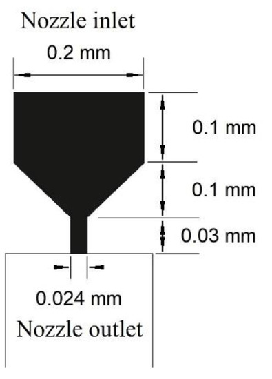
Figure 2.
Geometric parameters of the inkjet nozzle.
Initially, the space between the inlet and the nozzle outlet is filled with ink. Then, ink is ejected through the nozzle during a period of 2.0 μs and it is consequently forced to flow out of the nozzle. When the ejection stops, a droplet volume still grows for a while and snaps off the nozzle. After that, the droplet is changing form and continues to travel until it hits the target. During this process, gravity is considered, having a value 9.8066 m/s2.
To control the droplet size and velocity during the ejection, a rectangular function is applied (Figure 3) for the inlet velocity that forces a pressure increase inside the modeled nozzle. It helps to set the length of the pulse and the value of the maximum nozzle inlet fluid velocity magnitude (maximum value 0.2 m/s which is a realistic value to increase pressure in the inkjet nozzle for inkjet printing). Both parameters can affect the resulting velocity of the ejected droplet, but the magnitude (depends on the time of the droplet formation) has a larger influence on the droplet velocity.
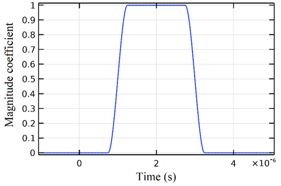
Figure 3.
Rectangle function of the increasing pressure in the nozzle.
4. Obtained Results
The droplet status considered at different instances in time will help to demonstrate the change of parameters of an ejected droplet which are represented by the considered points from A through F (Table 2; Figure 1 and Figure 2). Here, Dd.max determinates the droplet max diameter in the horizontal direction, while Dh determinates the droplet height in vertical direction. These basic points help to define the droplet status over time t.
Table 2.
Parameters of the considered inks at different points in time.
While analyzing the different ink parameters, firstly were calculated Reynolds, Weber, Ohnesorge, and Z numbers. Inks droplet parameter space with axes showing the Reynolds and Weber numbers are shown in Figure 4. Based on these numbers, all inks are suitable for inkjet printing, according to Derby [43,44] and Hoath [3]. But we can see some clear differences in droplet behavior, see Table 2.
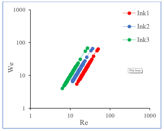
Figure 4.
Representation of the Reynolds and Weber numbers, showing the ink properties.
Droplet propagation parameters were obtained by COMSOL software. The related graphics can help to understand the behavior and properties of the droplet during ejection, progression in air, and surface interaction, whereby no wettability is considered. Droplet velocity after ejection is not bigger than 10 m/s and compared to Wijshoff [46,47] varies uniformly. Firstly, the droplet velocity during ejection, during the flight, and during impact is outlined in Figure 5.
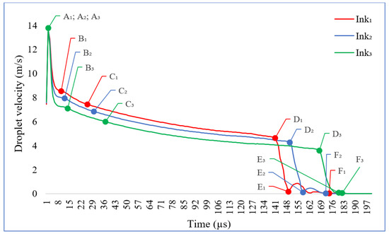
Figure 5.
Representation of the droplets (Ink1, Ink2, Ink3) velocity turnover. Velocity versus time.
At point A, the droplets of the different inks reach the same maximum velocity at the maximum pressure in the nozzle chamber leading to the ejection of the droplet. The B point corresponds to the droplet thread pulled off from the printhead nozzle—here, different inks have different starting velocities for droplet formation—-to assuming spherical form at point C where velocities do not change much.
Point D represents the beginning of the droplet interaction with the surface, the different inks reach various velocities before impact with the surface. At point E, the spreading moment, inks with bigger density and viscosity take final sphere form faster and do not oscillate much. Lower density and viscosity inks rebound more, which is possible to observe by the increasing velocity after the impact. Ink3 does not rebound and deposits least. Final point F represent the droplet in final-stable form which is reached at different times after the ejection: F1-174 µs (from D1 to F1-25 µs.), F2-172 µs (from D2 to F2-14 µs), F3-181 µs (from D3 to F3-2 µs). Droplets from Ink1 are not so viscous and after the impact, they rebound a few times up and down. That is why these inks reach stable phase later than Ink2. Ink3 does not oscillate and takes final form very fast after the impact with the surface.
In addition, we can address differences in the droplet forming parameters depending on time (Figure 6). Here, in Figure 6, Dd.max (Table 2) is the maximum droplet diameter (horizontal cross section); Dh (Table 2) is droplet height (vertical cross section).
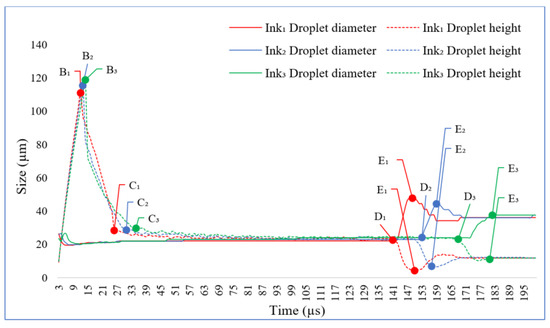
Figure 6.
Representation of the droplet size of Ink1, Ink2, Ink3 versus time.
If we compare the jets of the different inks regarding length and maximum diameter (horizontal cross section), few main differences can be noticed. Ink1 with lowest density and viscosity parameters has the smallest jet length and reveals the biggest oscillations. The droplet maximum spreading diameters is E1 = 47.7 µm. The droplet sphere diameter during flight is ~22 µm. The minimum spreading diameter has Ink3 which does not oscillate at all. The latter depends on droplet density and viscosity parameters—the droplet takes its final form then it touches the substrate.
It is important to know all these parameters if, for example, the use of UV curable inks is intended. Furthermore, after the droplet is generated, it is important to know the time period when the droplet reaches its final state on the surface. If we collate inks in this type of view, Ink2 reveals the best suitable result. Droplet from Ink2 does not oscillate much and has the smallest time period to reach a stable form on the surface. Droplets from Ink1 reach the surface faster but, in case of too low viscosity and density parameters, oscillate more strongly before they take their final form on the surface. For UV curable inks, it is very important to undergo this step in the stable phase of the droplet.
In the next graph (Figure 7), droplet mass change is demonstrated.
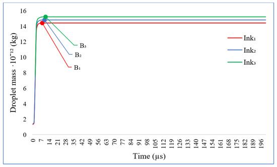
Figure 7.
Representation of the mass of the droplets (Ink1, Ink2, Ink3) versus time.
Droplet mass is integrated over the computational domain. At point A, the droplet reaches its maximum velocity and the droplet mass starts to increase during the first period till it reaches point B. At point B, the droplet thread is pulled off from the printing nozzle and mass is fully given. Droplets of different inks increase very similarly (Ink1 fully formed at 11 µs, Ink2-13 µs, Ink3-14 µs). When the liquid droplet is ejected, it needs a certain time and distance to reach the full spherical form and during the impact, it will lose its spherical shape and take final form on the surface. All these depend on the ejecting parameters, droplet velocity, nozzle configurations, and liquid characteristics. In order to examine the differences between ink droplets, their mass can be addressed, which are: Ink1 droplet = 14.4·10−12 kg, Ink2 droplet = 14.8·10−12 kg, Ink3 droplet = 15.2·10−12 kg. From this graphic, we can see that droplet mass stays fixed after point B when the droplet thread is pulled off.
In the next graphic (Figure 8), droplet volume formation is demonstrated.
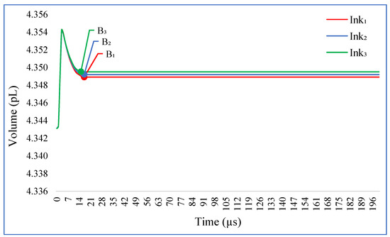
Figure 8.
Representation of the volume versus time of droplets of Ink1, Ink2, and Ink3.
Droplets reach their final volume at the same instance as already obtained for the mass. Inks with highest density and viscosity reach the largest volume: Ink1 droplet = 4.3491 pL, Ink2 droplet = 4.3493 pL, and Ink3 droplet = 4.3495 pL.
5. Discussion
The considered initial physical parameters, presented in Table 1, are the physical parameters of ink and air used in modeling the inkjet nozzle. These data allowed the replication of the physical behavior of the droplet. In addition, there are known guidelines within which the printing process can be performed. Droplet formation limits were evaluated and selected in the numerical investigation. Comparing to Dijksman [48], the droplet formation (point A) has similar manner, here velocity is increasing, until the droplet starts to separate from the nozzle (point B). Various formed droplet structures can be expected (Zhong et al. [17]). Physical experiments show that this is the case when a droplet is moving with high speed (up to 20 m/s), while having a speed variance with a large span from 0 to 19.414 m/s, Zhong et al. [17]. In our simulation, we had a lower speed variance up to 14 m/s and satellites were not observed. Our droplet therefore could be classified as a single droplet (Class 1, Zhong et al. [17]). But until it is formed, it changes its shape as well, which can be represented easily by applying COMSOL Multiphysics which allows modeling the change in speed, volume, and mass of the droplet.
The main aim of this research is to find the best modeling method for further investigations of different printing nozzle parameters, for printable fluid development and droplet ejection impulse parameters. This research should help to investigate printing technologies for broadening the new horizons of printing processes modeling. This work may be useful for further research to discover the best print head settings for printing with different inks or other chemical or biological fluids. It is important to mention that the work is focused on further research by modernizing the printing inks and print head parameters as well as the droplet printing parameters. It is important to note that inks that may now be unsuitable for printing can adapt perfectly if the shape of the print head shape and the pulse of irritation are properly selected.
In addition to the basics of known experiments, data were sufficient to perform a numerical experiment. In the future, by introducing more parameters and deepening into the droplet behavior, a physical experiment may be necessary. As a first step in revealing the fundamental properties of the droplet shape, moving to different forms, different units of time are sufficient for characterization. The numerical fulfilment itself is also important, as an implementation study with COMSOL. Such study will be useful for scientists who would like to carry out/to repeat and improve this study as well. By using COMSOL, the numerical modeling of the motion of inkjet droplets has been achieved. Using the software, the length of the drop thread, the moment when the drop is pulled out of the thread, when the droplet forms a spherical shape, droplet mass, droplet volume, droplet conditions on impact, and the final state of the droplet was found. In addition, it is now possible to configure different nozzle parameters, different ejection pressures, and test different inks. In addition, future investigations will be dedicated to considering different types of materials, e.g., [31,49].
6. Conclusions
It is known that during inkjet printing processes, it is important to know how fast the droplet forms a sphere; which speed it will have before interacting with the surface and what form it will have in the stable phase. It is also important to predict the interaction of the droplet with the surface. Technically, all of this has been obtained and implemented in the COMSOL Multiphysics software in the context of an improved inkjet nozzle application. Droplet ejection, motion, and impact were analyzed using the COMSOL CFD module. Numerical experiments were performed on this basis. The presented results on the inkjet printing process can accurately predict characteristic moments or even issues at an early state of the ink developing process. By the numerical model, all important key aspects of the inkjet printing process were assessed. These can directly affect printing quality. Known effects in physical printing have been observed and presented in a numerical experiment, such as:
- The droplet reaches its maximum velocity at the ejection moment when the pressure inside the nozzle is at the highest level.
- When the thread of the drop is detached from the nozzle, its speed is much lower and during flight, the speed of the drop decreases further.
- After impact, it is observed, that the drop loses its spherical shape and takes on a different form on the surface.
After the numerical experiments, it was observed that further research is needed to analyze the behavior of different inks with categorically different parameter settings, different ejection settings, different nozzle parameters and droplet impact with different surface parameters to further improve the printing process.
Author Contributions
T.T., V.T., H.K.-E. and R.J. conceived the presented idea; processed and analyzed the data, wrote the paper. All authors have read and agreed to the published version of the manuscript.
Funding
The research was funded by the Vilnius Gediminas Technical University (VGTU).
Institutional Review Board Statement
The study was conducted according to the guidelines of theDeclaration of Helsinki, and approved by the Ethics Committee of UNIVERSITAT POLITÈCNICADE VALÈNCIA (date of approval: 23 October 2018).
Informed Consent Statement
Informed consent was obtained from all subjects involved in the study.
Data Availability Statement
The data presented in this study are available on request from the corresponding author. The data are not publicly available due to privacy.
Conflicts of Interest
The authors declare no conflict of interest.
Nomenclature
| Roman | |
| d | the diameter of the nozzle (mm); |
| Dd.max | maximum droplet diameter (µm); |
| Dh | droplet height (µm); |
| DOD | drop-on-demand; |
| Fst | surface tension force (N); |
| gconst | acceleration due to gravity (m/s2); |
| md | droplet mass (kg); |
| n | the unit vector in the normal direction; |
| Oh | dimensionless coefficient; |
| p | pressure (Pa); |
| r | droplet radius (mm); |
| g | gravitational constant (m/s2); |
| Re | dimensionless coefficient; |
| t | time (s); |
| u | fluid velocity (m/s); |
| vd | droplet velocity (m/s); |
| Vd | droplet volume (pL); |
| We | dimensionless coefficient; |
| Z | dimensionless number. |
| Greek | |
| β | maximum spreading factor; |
| γ | parameter which determines the repetition of initiations; |
| δ | Dirac delta function; |
| ε | is the representative mesh size in the area passed by the falling droplet; |
| ĸ− | is the curvature; |
| η | is fluid viscosity (m/s); |
| μ | dynamic viscosity (N·s/m2); |
| ρ | density (kg/m3); |
| σ | surface tension coefficient (mN/m); |
| ϕ | coefficient of level set interface between air and ink. |
References
- The Future of Inkjet Printing to 2023 Report; SMITHER PIRA: Akron, OH, USA, 2018; Available online: https://www.smithers.com/services/market-reports/printing/the-future-of-inkjet-printing-to-2023 (accessed on 18 June 2018).
- Castrejon-Pita, J.R.; Baxter, W.R.S.; Morgan, J.; Temple, S.; Martin, G.D.; Hutchings, I.M. Future, opportunities and challenges of inkjet technologies. At. Sprays 2013, 23, 541–565. [Google Scholar] [CrossRef]
- Hoath, S.D. Fundamentals of Inkjet Printing: The Science of Inkjet and Droplets. John Wiley & Sons: Hoboken, NJ, USA, 2016; p. 472. [Google Scholar] [CrossRef]
- Stringer, J.; Derby, B. Limits to feature size and resolution in ink jet printing. J. Eur. Ceram. Soc. 2009, 29, 913–918. [Google Scholar] [CrossRef]
- Wijshoff, H. The dynamics of the piezo inkjet printhead operation. Phys. Rep. 2010, 491, 77–177. [Google Scholar] [CrossRef]
- Bos, A.V.D.; Meulen, M.J.V.D.; Driessen, T.; van den Berg, M.; Reinten, H.; Wijshoff, H.; Versluis, M.; Lohse, D. Velocity profile inside piezoacoustic inkjet droplets in flight: Comparison between experiment and numerical simulation. Phys. Rev. Appl. 2014, 1, 014004. [Google Scholar] [CrossRef]
- Yuzo, I.; Shinji, K.; Yoshimitsu, A.; Yasuhiro, A. Inkjet fabrication of polymer microlens for optical-i/o chip packaging. Jpn. J. Appl. Phys. 2000, 39, 1490–1493. [Google Scholar] [CrossRef]
- Ainsley, C.; Reis, N.; Derby, B. Freeform fabrication by controlled droplet deposition of powder filled melts. J. Mater. Sci. 2002, 37, 3155–3161. [Google Scholar] [CrossRef]
- Sachlos, E.; Reis, N.; Ainsley, C.; Derby, B.; Czernuszka, J.T. Novel collagen scaffolds with predefined internal morphology made by solid freeform fabrication. Biomaterials 2003, 24, 1487–1497. [Google Scholar] [CrossRef]
- Aqeel, A.B.; Mohasan, M.; Lv, P.; Yang, Y.; Duan, H. Effects of nozzle and fluid properties on the drop formation dynamics in a drop-on-demand inkjet printing. Appl. Math. Mech. 2019, 40, 1239–1254. [Google Scholar] [CrossRef]
- Fuller, S.B.; Wilhelm, E.J.; Jacobson, J.M. Ink-jet printed nanoparticle microelectromechanical systems. J. Microelectromechanical Syst. 2002, 11, 54–60. [Google Scholar] [CrossRef]
- Korvink, J.G.; Smith, P.J.; Shin, D.H. Inkjet-Based Micromanufacturing; John Wiley & Sons: Hoboken, NJ, USA, 2012; p. 388. [Google Scholar] [CrossRef]
- Martin, G.D.; Hoath, S.D.; Hutchings, I.M. Inkjet Printing-the Physics of Manipulating Liquid Jets and Drops. J. Phys. Conf. Ser. 2008, 105, 012001. [Google Scholar] [CrossRef]
- Wu, H.C.; Lin, H.J.; Kuo, Y.C.; Hwang, W.S. Simulation of droplet ejection for a piezoelectric inkjet printing device. Mater. Trans. 2004, 45, 893–899. [Google Scholar] [CrossRef]
- Tan, H.; Torniainen, E.; Markel, D.P.; Browning, R.N. Numerical simulation of droplet ejection of thermal inkjet printheads. Int. J. Numer. Methods Fluids 2015, 77, 544–570. [Google Scholar] [CrossRef]
- Abbas, Z.; Wang, D.; Du, Z.; Quian, J.; Zhao, K.; Du, Z.; Wang, Z.; Cui, Y.; Zhang, X.; Liang, J. Numerical simulation of electrohydrodynamic jet and printing micro-structures on flexible substrate. Microsyst. Technol. 2020. [Google Scholar] [CrossRef]
- Zhong, Y.; Dong, X.; Yin, Z.; Fang, H. Theoretical design of inkjet process to improve delivery efficiency. J. Appl. Fluid Mech. 2020, 13, 275–286. [Google Scholar] [CrossRef]
- Imani Moqadam, S.; Mädler, L.; Ellendt, N. A high temperature drop-on-demand droplet generator for metallic melts. Micromachines 2019, 10, 477. [Google Scholar] [CrossRef]
- Imani Moqadam, S.; Mädler, L.; Ellendt, N. Microstructure adjustment of spherical micro-samples for high-throughput analysis using a drop-on-demand droplet generator. Materials 2019, 12, 3769. [Google Scholar] [CrossRef]
- Elele, E.; Shen, Y.; Boppana, R.; Afolabi, A.; Bilgili, E.; Khusid, B. Electro-hydrodynamic drop-on-demand printing of aqueous suspensions of drug nanoparticles. Pharmaceutics 2020, 12, 1034. [Google Scholar] [CrossRef]
- Kim, S.H.; Kang, H.; Kang, K.; Lee, S.H.; Cho, K.H.; Hwang, J.Y. Effect of meniscus damping ratio on drop-on-demand electrohydrodynamic jetting. Appl. Sci. 2018, 8, 164. [Google Scholar] [CrossRef]
- Jiang, H.; Tan, H. One dimensional model for droplet ejection process in inkjet devices. Fluids 2018, 3, 28. [Google Scholar] [CrossRef]
- Wang, J.; Huang, J.; Zhang, J. A method for calculating the critical velocity of microdroplets produced by circular nozzles. 3D Print. Addit. Manuf. 2020, 7, 338–346. [Google Scholar] [CrossRef]
- Wang, F.; Bao, W.; Wang, Y.; Wang, X.; Ren, K.; Wang, Z.; Li, J. Ejection state prediction for a pneumatic micro-droplet generator by BP neural networks. J. Adv. Mech. Des. Syst. Manuf. 2020, 14, JAMDSM0001. [Google Scholar] [CrossRef]
- Pan, Y.; Zeng, L. Simulation and validation of droplet generation process for revealing three design constraints in electrohydrodynamic jet printing. Micromachines 2019, 10, 94. [Google Scholar] [CrossRef]
- Zymelka, D.; Yamashita, T.; Sun, X.; Kobayashi, T. Printed strain sensors based on an intermittent conductive pattern filled with resistive ink droplets. Sensors 2020, 20, 4181. [Google Scholar] [CrossRef]
- Cui, W.; Zhang, M.; Duan, X.; Pang, W.; Zhang, D.; Zhang, H. Dynamics of electrowetting droplet motion in digital microfluidics systems: From dynamic saturation to device physics. Micromachines 2015, 6, 778–789. [Google Scholar] [CrossRef]
- Liu, Y.; Huang, Y. Theoretical and experimental studies of electrostatic focusing for electrohydrodynamic jet printing. J. Micromech. Microeng. 2019, 29, 065002. [Google Scholar] [CrossRef]
- Liashenko, I.; Rosell-Llompart, J.; Cabot, A. Ultrafast 3D printing with submicrometer features using electrostatic jet deflection. Nat. Commun. 2020, 11, 753. [Google Scholar] [CrossRef]
- Ou, C. Aerosol-Jet Printed Nanocomposites for Flexible and Stretchable Thermoelectric Generators. Ph.D. Thesis, University of Cambridge, Cambridge, UK, 2020. [Google Scholar] [CrossRef]
- Dybowska-Sarapuk, L.; Kielbasinski, K.; Arazna, A.; Futera, K.; Skalski, A.; Janczak, D.; Sloma, M.; Jakubowska, M. Efficient inkjet printing of graphene-based elements: Influence of dispersing agent on ink viscosity. Nanomaterials 2018, 8, 602. [Google Scholar] [CrossRef]
- Tortorich, R.P.; Choi, J.-W. Inkjet printing of carbon nanotubes. Nanomaterials 2013, 3, 453–468. [Google Scholar]
- Wickström, H.; Hilgert, E.; Nyman, J.O.; Desai, D.; Şen Karaman, D.; De Beer, T.; Sandler, N.; Rosenholm, J.M. Inkjet printing of drug-loaded mesoporous silica nanoparticles—A platform for drug development. Molecules 2017, 22, 2020. [Google Scholar] [CrossRef]
- Wang, J.; Krishnamoorthy, S.; Song, H.; Ma, C. Mechanical properties of 3D-printed blood vessels. DYNA Ing. Ind. 2020, 9, 541–545. [Google Scholar] [CrossRef]
- Grottkau, B.E.; Hui, Z.; Pang, Y. A novel 3D bioprinter using direct-volumetric drop-on-demand technology for fabricating micro-tissues and drug-delivery. Int. J. Mol. Sci. 2020, 21, 3482. [Google Scholar] [CrossRef] [PubMed]
- Son, Y.; Kim, C.; Yang, D.H.; Ahn, D.J. Spreading of an inkjet droplet on a solid surface with a controlled contact angle at low Weber and Reynolds numbers. Langmuir 2008, 24, 2900–2907. [Google Scholar] [CrossRef] [PubMed]
- Bussmann, M.; Chandra, S.; Mostaghimi, J. Modeling the splash of a droplet impacting a solid surface. Phys. Fluids 2000, 12, 3121–3132. [Google Scholar] [CrossRef]
- Driessen, T. Drop Formation from Axi-Symmetric Fluid Jets. Ph.D. Thesis, University of Twente, Enschede, The Netherlands, 2013. [Google Scholar]
- Olsson, E.; Kreiss, G. A conservative level set method for two phase flow. J. Comput. Phys. 2005, 21, 225–246. [Google Scholar] [CrossRef]
- Sun, Y.; Beckermann, C. Sharp interface tracking using the phase-field equation. J. Comput. Phys. 2007, 220, 626–653. [Google Scholar] [CrossRef]
- CFD Module User’s Guide; COMSOL: Burlington, MA, USA, 2018.
- Sohr, H. The Navier-Stokes Equations: An Elementary Functional Analytic Approach; Springer Science & Business Media: Berlin, Germany, 2012; p. 367. [Google Scholar] [CrossRef]
- Derby, B. Inkjet printing of functional and structural materials: Fluid property requirements, feature stability, and resolution. Annu. Rev. Mater. Res. 2010, 40, 395–414. [Google Scholar] [CrossRef]
- Derby, B. Additive manufacture of ceramics components by inkjet printing. Engineering 2015, 1, 113–123. [Google Scholar] [CrossRef]
- Magdassi, S. The Chemistry of Inkjet Inks; World Scientific: Singapore, 2010. [Google Scholar] [CrossRef]
- Wijshoff, H. Drop dynamics in the inkjet printing process. Curr. Opin. Colloid Interface Sci. 2018, 36, 20–27. [Google Scholar] [CrossRef]
- Wijshoff, H. Structure- and Fluid-Dynamics in Piezo Inkjet Printheads. Ph.D. Thesis, University of Twente, Enschede, The Netherlands, 2008. [Google Scholar]
- Dijksman, J. Hydro-acoustics of piezoelectrically driven ink-jet print heads. Flow Turbul. Combust. 1999, 61, 211–237. [Google Scholar] [CrossRef]
- Venezia, E.; Viviani, M.; Presto, S.; Kumar, V.; Tomov, R.I. Inkjet Printing Functionalization of SOFC LSCF Cathodes. Nanomaterials 2019, 9, 654. [Google Scholar] [CrossRef]
Publisher’s Note: MDPI stays neutral with regard to jurisdictional claims in published maps and institutional affiliations. |
© 2021 by the authors. Licensee MDPI, Basel, Switzerland. This article is an open access article distributed under the terms and conditions of the Creative Commons Attribution (CC BY) license (http://creativecommons.org/licenses/by/4.0/).