Abstract
Currently, new housing in city centers is more and more often developed on small plots of land, or existing buildings on such plots are rebuilt to such an extent that only their façade walls remain. In both cases, as a rule, a deep excavation is also made, either at the existing object or within its area. Serious damage often occurs because of the carried out work. It is not possible to accurately determine the response of a building to the deformation associated with the excavation due to the variability of many factors that influence it. As a result, the response of the building must be estimated on the basis of constant monitoring and approximate calculations. Depending on the size of the predicted ground displacements and the technical condition of buildings, it is often necessary to protect or strengthen their structural elements. In the paper, the authors analyzed various risk factors for the implementation of infill buildings and the revitalization of historic buildings using only their façade walls. In addition, examples of contemporary solutions for securing the walls of existing buildings, and the method of monitoring vertical deformations using the Hydrostatic Levelling Cell (HLC) system, are presented.
1. Introduction
It has recently become general practice to use small building plots located in dense urban housing. In such places, infill buildings are constructed, or historic buildings are revitalized using their façade walls for the construction of new objects [1,2]. In both cases, the construction projects involve deep excavation work. During the construction of infill buildings, these excavations can cause serious damage to existing buildings located in the surrounding neighborhood. However, when erecting a building that uses historic façade walls, the excavations have an impact on the structure of these walls and their foundations [3]. As a result of ground deformations additional forces are generated in the elements and their connections as well as additional deformations and displacements. It is the horizontal and vertical displacements of existing structures that are an important factor when assessing the degree of risk of structural collapse. The inclination of the building from the vertical axis is usually allowed up to a value of 3 per mille [4], and its settlement to a value ranging from 5 to 15 mm [5]. Inclinations of existing buildings from their vertical axis cause additional horizontal forces (which are the components of vertical loads) in the elements of the structures. The horizontal forces that act on the entire structure must be transferred by its load-bearing systems under the required conditions of stability and strength, or by external designed supports.
In general, an investment in a dense downtown housing development, in order to ensure the stability of existing buildings, should include [6]:
- -
- the identification of soil and water conditions under the designed building structure and in the zone of its impact on surrounding buildings;
- -
- the defining of the requirements for functional and spatial solutions of the underground part of the investment;
- -
- the determination of the zones of impact of the designed object on neighboring buildings;
- -
- the protecting and strengthening of the walls of existing buildings;
- -
- the monitoring of the vertical deformations of existing buildings.
The article presents examples of the innovative support (protection) of the walls of existing buildings in dense urban housing, and also presents the system of monitoring vertical deformations with the use of the hydrostatic levelling cell (HLC) system.
2. Methods
In dense urban developments, a common problem is deep excavations which are adjacent to existing buildings. In this case, it is important to assess the impact of excavation construction on the surrounding soil and adjacent buildings, and also to estimate soil settlement for the proper design of the new structure. From a technical point of view, the condition of adjoining buildings is usually critical due to the weakness of the structural system or the shallow depth of the foundations. As a result of deep excavations, lateral and vertical soil displacements occur. Lateral loads cause bending moments and foundation deflections, which can lead to dangerous increases in stress or damage to the structure. Many failures have occurred due to the inadequately supported excavations, walls and foundations of existing buildings. The choice of the support system is affected by many factors. These include, for example, the type of soil, the type of foundation, the height of the building under construction, the level of foundation of neighboring buildings, as well as the budget of the investment. In order to limit soil displacement and deformation as a result of deep excavation, various support systems are used. The authors of this paper present recommendations for the implementation of a deep excavation in the form an innovative system for supporting the walls of existing buildings and for monitoring them, which is especially important from the point of view of the engineers responsible for the construction of the object. The article uses a method that includes the following elements:
- -
- collecting information on the implementation of infill buildings and the revitalization of historic buildings with the use of façade walls in the vicinity of deep excavations;
- -
- interpretation and synthesis of collected information on the basis of literature and the authors’ own design experience related to the applied protection and monitoring systems.
3. Methodology for Determining the Impact of Deep Excavation on Existing Buildings, the Designing of Their Protection, and the Monitoring of Their Technical Condition
When designing buildings that require a deep excavation in the surrounding neighborhood of existing urban housing, it is necessary to estimate the range of the excavation impact zone, as well as to determine which buildings are located in this zone. For these buildings, expert opinions regarding the technical condition of their structures should be made. This will enable the possibility of transferring additional loads by the structure of these buildings (due to the anticipated uneven ground movement in the area of their foundation) to be determined. The expert opinions should also define the permissible displacements for these buildings. There are many methods in the literature of determining ground movements. Some of these methods are empirical and include all the interactions involved in the erection of a building [7,8], wheras others only describe a specific aspect in which individual interactions combine [9,10,11]. Different approach represents numerical methods which concern the displacement-induced damages to existing structures located in the vicinity of excavation [12,13,14]. Most recently design methodologies were proposed to estimate the damage to buildings adjacent to deep excavations using probabilistic or semi probabilistic analyses [15,16,17,18].
The measures of the displacements of buildings that are adjacent to the construction of deep excavations include tilts, deflections, and cracks of structural elements [19]. The value of the vertical displacements of the terrain surface and the shape of the settling basin depend primarily on the type of used excavation casing and the type of ground foundation. The range of impact of the excavations depends on the deformability of the soil, the depth of the excavations, the dimensions of the plan of the excavations, the possible presence of groundwater and the stiffness of the excavation casing. The scopes of the applied construction protections are different and depend on a specific situation [20,21,22]. The most common external protections are in the form of a diaphragm wall, i.e., a Berliner wall (lagging wall), a sheet pile wall, and a retaining column wall made by jet grouting and mixed technologies (Figure 1). The stability of deep excavation casing made with one of these technologies is additionally ensured by bracing struts, ground anchors (Figure 2), or the floor slabs of underground storeys [23]. If there are relatively small spans, the bracing struts can be made of wide-flange I-sections. Larger spans require bracing that uses steel tubes with a diameter of 400–800 mm [24]. In addition to the compressive forces and the bending moment derived from excavation support load, very large impact on the axial forces comes from the thermal effects. In order to determine the real effect of temperature on the bracing strut, the susceptibility of their props needs to be determined.
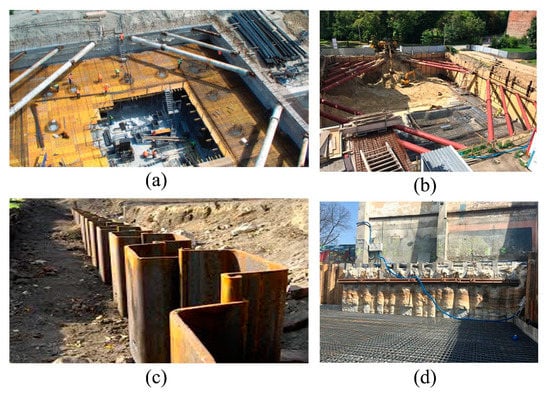
Figure 1.
Various structural solutions for deep excavation support: (a) diaphragm wall, (b) Berliner wall (lagging wall), (c) sheet pile wall, (d) retaining column wall made by jet grouting (developed by authors).
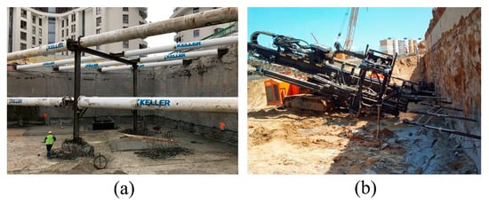
Figure 2.
Structural solutions to ensure the stability of a deep excavation: (a) bracing struts, (b) ground anchors (developed by authors).
In the case when the building structure is not able to transfer these additional loads, it is necessary to design the structure’s reinforcement and ground foundation [25].
Various methods can be used to increase the bearing capacity of foundations. One commonly used method is the classical method, which involves the excavating of the foundations followed by the underpinning of them, or the extending of the foundations while assuming that there is no water at the depth of the intended works, with the height of the underpinning not exceeding 3 m.
The walls of existing buildings can also be reinforced using injection micro piles and statically pressured micro-piles, as well as drill and screw micro-piles, the advantage of which is their high rigidity. These elements are shown in Figure 3.
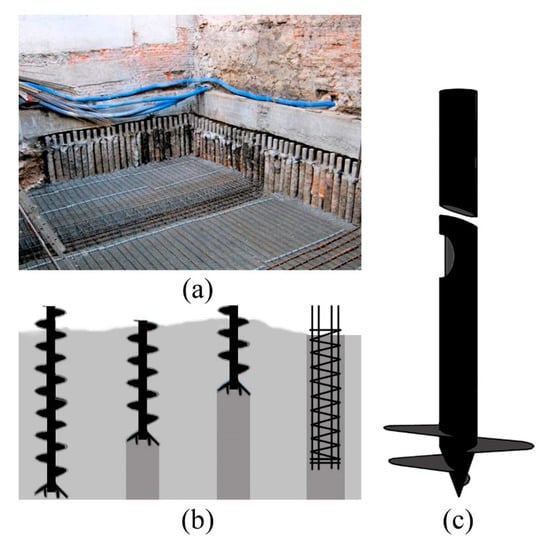
Figure 3.
Additional structural elements that are used to transfer loads from the deeper layers of soil with a higher load-bearing capacity: (a) injection micro-piles, (b) drill micro-piles, (c) screw micro-piles (developed by authors).
Currently, the most common method of strengthening existing building, especially historic ones is underpinning by means of jet grouting injections (Figure 4).
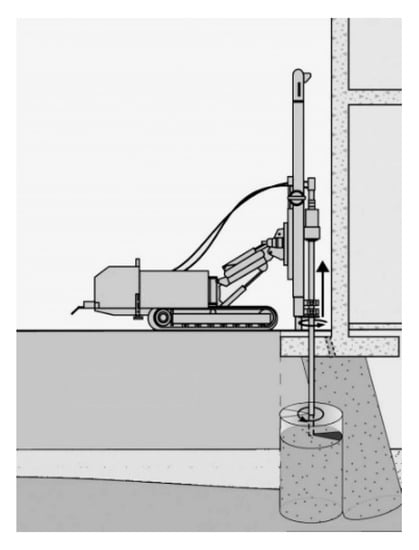
Figure 4.
Increasing the bearing capacity of a foundation by means of jet grouting (developed by authors).
Estimating the impact of an excavation on neighboring buildings involves:
- -
- the determination of the impact range of the excavation (impact zone),
- -
- the determination of the vertical and horizontal displacements of the excavation casing and the adjacent area,
- -
- the determination of the expected horizontal and vertical displacements of adjacent buildings;
- -
- making sure that the expected displacements of existing buildings are lower than their maximum limit displacements.
The range of the excavation impact zone is determined with regards to the type of soil and the depth of the excavation. According to various studies presented in the literature, this range is a multiple of the excavation depth H and depends on the type of soil and the excavation casing, as shown in Table 1. The impact zone can also be determined with regards to the shape and width of the foundation of the erected building, the amount of pressure at its base, and the average value of the deformation modulus in the settling soil layer. The forecasted vertical displacements of the ground surface in the close vicinity of the excavations, which can be found in literature, are summarized in Table 2.

Table 1.
The range of the excavation impact zone [23].
Table 2.
Summary of the values of vertical displacements [23].
Vertical displacements of the soil in the zone adjacent to an erected building are the result of the superposition of displacements from individual stages of works, including the execution of the casing, the deepening of the excavation and the supporting of its casing, the implementing of the underground part of the building, the erecting of the entire aboveground structure, and also the impact of the conditions of using the building. For existing buildings, two types of allowable limit displacements are defined-the first [sk]u due to the serviceability limit state, and the second [sk]n due to the ultimate limit state. For the first condition, cracks of a small width are allowed, which may then be painted or smoothed. In the second condition, the appearance of cracks and failures that require repair are allowed, but they must not threaten the safety of the building. Approximate values of the maximum limit displacements for buildings according to [5] are given in Table 3.
Table 3.
Approximate values of the maximum limit displacements for buildings according to [5].
4. Monitoring of the Technical Condition of Existing Buildings
Monitoring of the technical condition of existing buildings is the most important element when controlling construction works and ensuring the safety of these objects [33,34]. The scope of observation of the structures of existing buildings depends on their location and the distance from a new investment. It usually includes the geodetic measurements of horizontal and vertical displacements for walls in the direct vicinity of the executed excavation, building observation, and possibly the measuring of the width of existing cracks with feeler gauges. An exemplary instrument for measuring the width of cracks is shown below in Figure 5. Other less frequently used monitoring methods are strain gauge, which measures deformation using foil strain gauges, and piezometric which is installed to control groundwater levels.
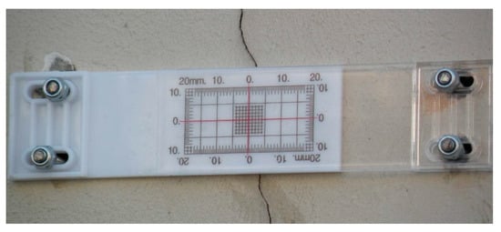
Figure 5.
An exemplary instrument used to measure the width of cracks (photograph by authors).
The frequency of measurements should be adapted to the course of the construction works and the current technical condition of the building. Conducting traditional geodetic measurements allows the results of displacements to be obtained in quite significant time intervals, which is often insufficient in relation to the significant dynamics and the speed of the phenomena occurring in the excavation. Therefore, systems that allow for the continuous measurement of displacements of existing buildings and the obtaining of measurement results on-line are becoming more and more popular. One of them is the innovative hydrostatic leveling cells system, which measures the vertical displacements of structures in real time with high accuracy using a network of connected sensors [35].
The system is characterized by high accuracy measurement and was designed to measure the vertical movement of structural elements. Its measuring range applies to displacements of up to ±500 mm. The mounted sensors create a map of the 2D measurement network, which can then monitor the vertical displacements of the structure over the entire surface. Contour line plots can be generated over time to directly detect which area should be analyzed. All the sensors of the system are connected to each other with the same liquid pipe and then connected to the liquid expansion tank, which is located above the entire measuring system. This method of system construction allows the appropriate pressure to be forced inside. The vertical displacements of individual sensors mounted on the structure cause pressure changes inside the system, which are measured in the place of the installed sensors. When the sensor moves vertically, the corresponding liquid height changes accordingly, independent of all the other sensors. As liquid pressure can be measured very accurately at each sensor, vertical movement can be calculated from the density of the used liquid. Each sensor is also connected to each other sensor by an air pipe in order to normalize the reference pressure between the sensors. When the structure settles down, the measuring cells settle with the structure, in turn increasing the pressure in the system. Therefore, a settlement measurement can be performed. Lifting of the structure is similarly detected, i.e., when the liquid pressure in the system is reduced. The HLC system is fully integrated with the software system, e.g., the Quickview interface. Data is streamed online within minutes, so movements of the structure can be monitored in real time. Supervision over the measured structure is clearly achieved by means of a simple graphic visualization and automatically generated reports. If the measurement shows that the displacements of the structure have exceeded the previously set alarm thresholds, the system can send automatic notifications. An example of an HLC system application is shown in Figure 6, Figure 7 and Figure 8. This system was installed along the facades of buildings and around the planned earthworks (excavations) related to the revitalization of a historic hotel building in the center of Wroclaw.
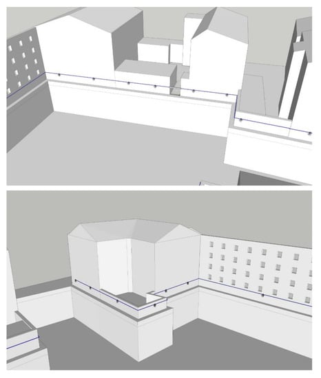
Figure 6.
Automatic measurement of vertical deformations (settlements) using a hydrostatic leveling cell system (HLC) in installed along façades of buildings around the planned earthworks (developed by authors).
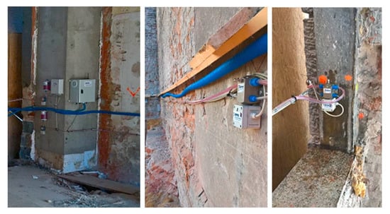
Figure 7.
HLC system for baseline measurements with data transfer to the GETEC server (photograph by authors).
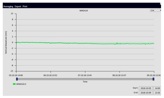
Figure 8.
Graph of vertical displacements from monitoring and Quickview GETEC software (developed by the authors).
An additional system for monitoring a building’s geometry is a system of wireless inclinometers installed on the façades of the building (Figure 9 and Figure 10). This system consists of a control and monitoring module, and also sensor modules to which an inclinometer and a thermometer are connected. The inclinometer is a high-precision measuring device that is used in the construction of cranes, wind turbines and ships. Temperature measurement is used to assess its influence on the operation of the inclinometer and the measured structure. The sensor modules record data from the inclinometer and thermometer and save them in random access memory. On the command sent from the monitoring and control module, they perform the required calculations and send their results to the database.
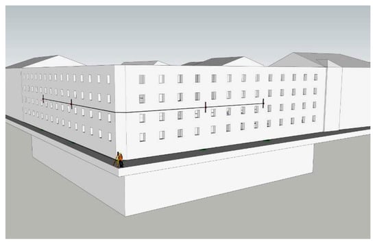
Figure 9.
Automatic measurement of changes in façade inclinations using wireless, automatic inclinometers (developed by authors).
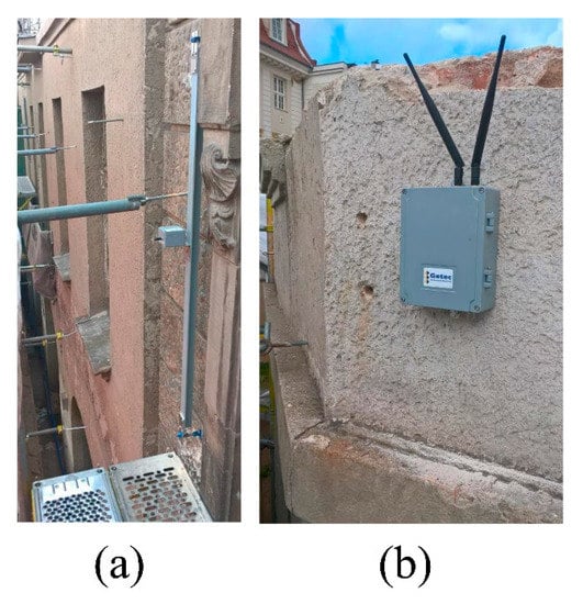
Figure 10.
The wireless inclinometer system: (a) installation on two façades of the building, (b) a control computer for transmitting measurement data located on the top storey at the corner point between two façades (photograph by authors).
5. Protection of the Walls of Existing Buildings
In many building revitalization projects, the existing brick or stone façade is kept and is temporarily supported by a steel structure while the rest of the building is demolished. In the internal space, a new supporting structure of the building is erected, and then adapted to the modern technical requirements and the expectations of future users. The façade walls are anchored to the new support structure and carefully restored. In this way, the appearance of the building does not change, but its usability is significantly improved. However, before this happens, the stability of the walls, often of considerable height, must be supported during the process of construction. The support may be realized by means of horizontal steel ties made of bars and located on several levels, or by means of stiffening or bracing elements [36,37].
Examples of supporting an existing masonry façade wall with an external temporary steel framework are shown in Figure 11, Figure 12, Figure 13 and Figure 14. Figure 11 shows the temporary supporting structure for the façade of a revitalized textile factory building that is having its function changed into a cultural, recreational, and commercial center. The supporting structure is anchored to concrete blocks.
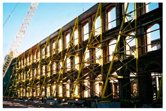
Figure 11.
Temporary protection for the façade wall in the form of a strut-and-tie steel structure [3].
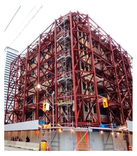
Figure 12.
Temporary protection for the façade wall in the form of a steel frame structure [1].
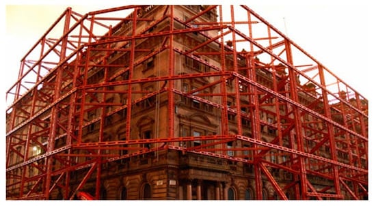
Figure 13.
Temporary protection for a façade wall in the form of a steel frame structure [22].
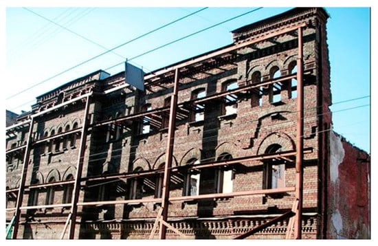
Figure 14.
Temporary protection for a façade wall in the form of a steel buttresses (photograph by authors).
The temporary protection for façade walls in the form of a steel spatial frame is shown in Figure 12. This design required the strengthening of the foundations using micro piles. In this case, the façade walls were adapted to the new architectural concept, which involved incorporating the historic building into a complex of two high-rise residential towers.
Another example of the application of the temporary protection of façade walls with the use of a steel space frame is shown in Figure 13.
Figure 14 shows temporary protection in the form of steel buttresses with horizontal sections attached to them, which are fixed to the wall with steel connectors Steel buttresses can be constrained to the ground with the use of piles or concrete blocks that operate as a ballast.
The main disadvantage of the above-mentioned typical solutions for supporting façade walls is the very high consumption of steel for the buttresses, as well as the occupation of the area around the walls. In dense downtown housings, especially for buildings located on busy streets, it is often impossible to support the walls on the side of the street or sidewalk. On the other hand, the arrangement of the steel supporting structure from the inside of the building makes it impossible to carry out excavation work or erect new foundations. An innovative method of supporting walls, which is used for the reconstruction of a historic hotel in the center of Wroclaw, is presented below. Figure 15 shows the Push-Pull Props support structure used for the remaining façade walls of the modernized building. This structure is extendable with an extension length of up to 14 m.
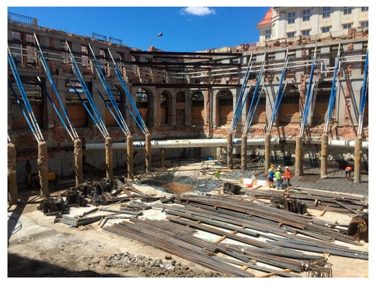
Figure 15.
Temporary protection for a façade wall made of the PERI Push-Pull Props support structure (photograph by authors).
The PERI Push-Pull Props system was used for bracing the walls and was anchored in points in specially made micro piles. Due to the large height of the remaining walls, the support was made in 3 levels, as shown in Figure 16.
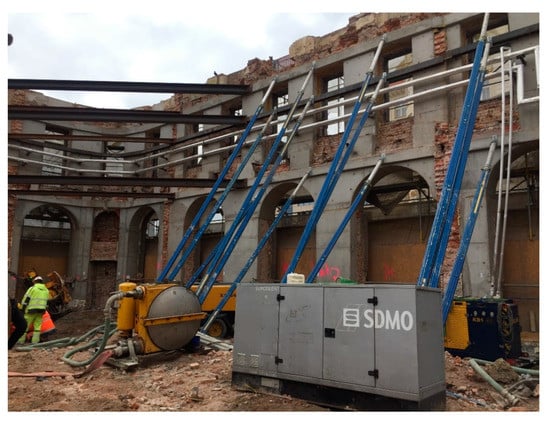
Figure 16.
Supporting the walls of the existing building in 3 levels with the PERI Push-Pull Props system (photograph by authors).
The steel support structures were anchored in the previously made heads of reinforced concrete piles. This enabled the appropriate load-bearing mounting of these supports, and at the same time, collision-free work related to the excavation and construction of the foundation slab. After the slab floors in the new building are finished, the support will be dismantled. Then, after sealing the pile contact with the foundation slab, they will be cut out. Figure 17 shows the details of anchoring the PERI Push-Pull Props system to the pile head.
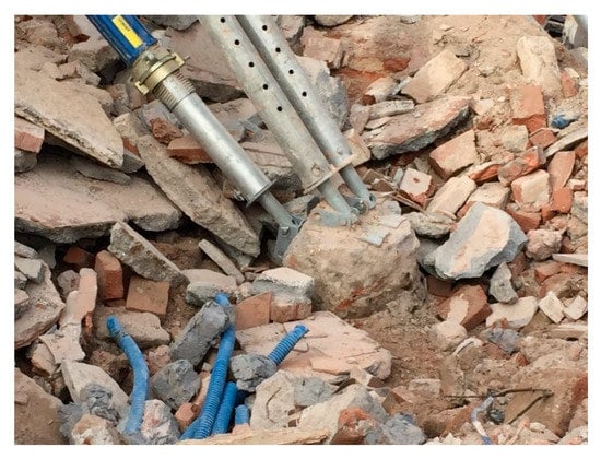
Figure 17.
Anchoring of the PERI Push-Pull Props system to the pile head (photograph by authors).
During construction works in the vicinity of existing buildings, especially deep excavations for garages designed in new buildings, excessive movements of these objects, despite the applied protection systems described in Section 2, often occur. This results in significant damage and excessive deflection of the walls, which may lead to the collapse of the construction. In this case, it is necessary to quickly support the walls in order to stabilize them. In such cases, a common solution is to use temporary steel braces of the strut-cantilever or tie type. An example of this type of bracing is shown in Figure 18.
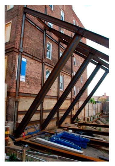
Figure 18.
Temporary steel bracing of the strut-cantilever type (photograph by the authors).
A disadvantage of such solutions is the high consumption of steel, but also the time-consuming implementation, which can be essential when you need to quickly support a wall. An alternative solution that can be used in such cases is presented below. It also uses the PERI Push-Pull Props system [38], which is fastened on one side to the supported wall, and on the other to e.g., reinforced concrete road slabs laid at the bottom of the excavation. The proposed solution, which is currently being implemented at a historic tenement house in a city center location, is shown schematically in Figure 19. This solution enables the wall support to be made almost immediately.
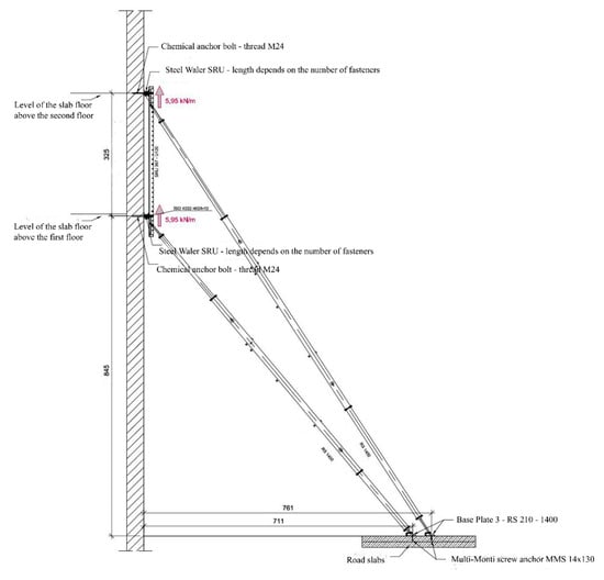
Figure 19.
An exemplary way of supporting an existing wall with the use of the PERI Push-Pull Props system (picture courtesy of PERI).
6. Case Study
The numerical analysis of the supporting structure–using PERI Push-Pull Prop system–of the walls of the rebuilt, historical building, situated around a deep foundation excavation, was presented in the paper (Figure 20 and Figure 21). The building undergoing modernization, erected at the end of the 19th century was rebuilt in the fifties of the 20th century. In plan, the building has dimensions 23.55 m × 16.10 m. The building has a basement, four overground storeys and an attic. On the south-west side, a corner building is adjacent to the gable wall of the analyzed building, while on the north-eastern side there is an empty area, where construction works of another residential development have started. The structural system of the building is longitudinal, with floor slabs supported at its front, rear and internal longitudinal walls.
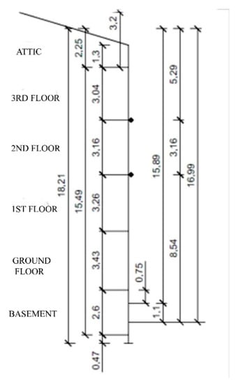
Figure 20.
The geometry of the gable wall.
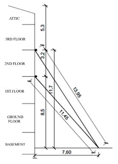
Figure 21.
Scheme of the gable wall support (PERI Push-Pull Props system).
In the conducted calculations loads from the wind suction, acting on the entire surface of the gable wall, as well as the horizontal component of the wall self-weight, resulting from the assumed 50 mm displacement at its top level, were applied (Figure 22). As a result of the numerical analysis optimal wall support was obtained at the level of the first and second floors using PERI RS 1400 brace struts with maximum reach of 14.00 m. Reinforced road-slabs, stabilized by their self-weight, were used to support the bracing struts.
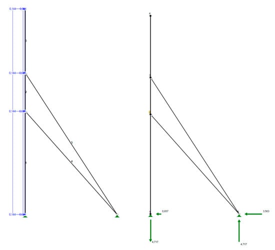
Figure 22.
The numerical model of the supporting structure of the gable wall.
7. Discussion
The search for space in the conditions of dense urban development sets the trend for deep excavations near densely arranged objects. Additionally, the presence of underground utilities and the necessity to limit the lateral movements of the soil make it extremely difficult to properly protect such a trench. Therefore, it requires combination of geotechnical, hydrological, structural, civil engineering and waterproofing expertise. The protections are implemented with diaphragm walls, steel sheet pile walls, large-diameter struts, walls made of columns by jet grouting, etc. These solutions are designed so that the protections are stable and that they limit the deformation caused by excavations to levels acceptable for neighboring buildings. To achieve this, computer simulations using the finite element method (PLAXIS 2D, MIDAS/GTS) are performed to demonstrate the behavior of these protections in terms of stress distribution and soil deformation characteristics under adjacent buildings in sensitive areas [39,40,41]. The model used for soil simulation is the Mohr-Coulomb model for an elastic-perfectly plastic material.
Another important aspect of this type of construction is the optimal reinforcement and protection of the walls and foundations of existing buildings. This reinforcement can be executed, e.g., using injection, drilled and screwed micro-piles. Traditionally, temporary steel spatial frames or strut-and-beam structures are used to support the walls of existing buildings. These solutions are not optimal due to the high consumption of steel and the large space around the building, which makes construction work very difficult. The recommended solution by the authors of the article is the Push-Pull Props system (PERI, Wroclaw, Poland), which, in combination with its fastening to reinforced concrete piles, is characterized by low steel consumption, quick assembly and disassembly, and no restriction of construction works inside the building. Monitoring is a very important issue related to the technical problems of construction near deep excavations and the ensuring of safety. Currently, the most innovative monitoring system is the hydrostatic leveling cell (HLC) system connected with a recording computer and an LTE modem for data transmission, which is used to measure the movement of structural elements. On the basis of real, continuous measurements made on-line, with the help of this system it is possible to create a database and develop accurate theoretical models of the response of existing buildings to construction works carried out nearby. The use of these models in the future will optimize the methods of protecting of existing buildings, and by introducing complete automation of deformation measurement, it will increase the safety of works.
8. Conclusions
The paper focuses on the problem of soil-structure interaction mechanisms for buildings located in the vicinity of deep excavations, as well as finding appropriate methods of designing their protection and reinforcements and monitoring their vertical deformations. During the realization of a new investment in the area of a dense housing development, in the case of infill buildings or revitalizing historic buildings using only their façade walls, there are always complex technical problems related to the safety of both the new and old buildings. The main purpose of using temporary steel bracing is to enable safe construction works and to prevent the uncontrolled collapse of a building or its parts. The main problem is that old buildings in new investments are not designed to transfer the loads associated with the implementation of these investments. The assessment of the reaction of buildings to deformations caused by deep excavations is influenced by the accuracy of determining the deformations and stress changes caused by these excavations. The interaction of the deep excavation and the existing building is bilateral. The movement of the soil causes deformation of the building and the possibility of cracks and other types of damage. Moreover, existing buildings modify the displacement of the ground directly below them. In this situation, geodetic measurements are very important, and in particular the monitoring of vertical displacements of existing buildings, which enables the objective determination of changes related to the safety of both old and new structures. The correct assessment of the impact of new buildings on the neighboring existing objects enables the use of appropriate protections and new technologies that allow the damage and failures of adjacent buildings to be eliminated. Currently, the leading solutions used in the modern structures of temporary bracings are steel bar braces of the Push-Pull Props system. A particularly innovative solution for supporting the walls of existing buildings is use of this system and its anchoring on reinforced concrete or steel micro-piles. The Push-Pull Props are characterized by a high ratio of strength to self-weight, thanks to which relatively small dimensions of both the bar sections and the supporting structures are obtained. In addition, their versatility is determined by the possibility of quick assembly and disassembly, a high degree of prefabrication, a high accuracy of matching individual elements to the dimensions of the existing structure, and the possibility of full recycling, which is in line with modern environmental protection requirements [42].
Author Contributions
Both authors contributed the same to the analysis of the problem, discussion and writing the paper. Both authors have read and agreed to the published version of the manuscript.
Funding
This research received no external funding.
Institutional Review Board Statement
Not applicable.
Informed Consent Statement
Not applicable.
Data Availability Statement
Not applicable.
Conflicts of Interest
The authors declare no conflict of interest.
References
- Gordon, A.; Sousa, M.; Isherwood, B. Heritage Facade Support and Excavation Shoring—A Micropile Case History. In Proceedings of the 13th International Workshop on Micropiles, Vancouver, BC, Canada, 29 March–1 April 2017; pp. 1–19. [Google Scholar]
- Highfield, D. The Construction of New Buildings behind Historic Façades; CRC Press: Boca Raton, FL, USA, 1991. [Google Scholar]
- Seruga, T.; Płachecki, M.; Seręga, S. Structural Problems of Adaptation of Historic Post-Industrial Buildings to New Function. Tech. Trans. 2009, R. 106, z.2_B, 317–325. (In Polish) [Google Scholar]
- Runkiewicz, L. Wzmacnianie i zabezpieczanie istniejących obiektów w sąsiedztwie realizowanych budynków plombowych. Prz. Bud. 2008, 4, 28–38. (In Polish) [Google Scholar]
- Kotlicki, W.; Wysokiński, L. Protection of buildings adjacent to deep excavations. ITB Recomendations 2002. (In Polish) [Google Scholar]
- Runkiewicz, L.; Sieczkowski, J. Problemy techniczne budowy obiektów na terenie istniejącej gęstej zabudowy. Prz. Bud. 2015, 9, 18–23. [Google Scholar]
- Peck, R.B. Deep excavations and tunneling in soft ground (State of the Art Report). In Proceedings of the 7th International Conference of Soil Mechanics, Mexico City, Mexico, 25–29 August 1969; Volume 7, pp. 225–290. [Google Scholar]
- Goldberg, D.T.; Jaworsky, W.E.; Gordon, M.D. Lateral Support Systems and Underpinning. Volume I: Design and Construction. In Federal Highway Administration; Report No. FHWA-RD-75-128; Bureau of Transportation Statistics, U.S. Department of Transportation: Washington, DC, USA, 1976; Volume 1. Available online: https://rosap.ntl.bts.gov/view/dot/14528 (accessed on 15 September 2020).
- Clough, G.W.O.; Rourke, T.D. Construction induced movements of in-situ walls. In Design and Performance of Earth Retaining Structures; ASCE Special Publication No. 25; 1990; pp. 439–470. Available online: faculty.uml.edu/spaikowsky/14.533 Adv Found Eng/Documents/Const Induced Moments_Clough&O’Rourke_1990.pdf (accessed on 15 October 2020).
- Moorman, C.; Moorman, H.R. A study of wall and ground movements due to deep excavations in soft soil based on worldwide experiences. In Geotechnical Aspects of Underground Construction in Soft Ground, Kastner, Emeriault, Dias, Guilloux (eds); 2002; pp. 477–482. Available online: https://www.issmge.org/uploads/publications/6/10/2002_070.pdf (accessed on 15 October 2020).
- Konstantakos, D.C.; Regalado, A.J.W.C.; Scharner, B. Control of Ground Movements for a Multi-Level-Anchored, Diaphragm Wall During Excavation. In Proceedings of the Fifth International Conference on Case Histories in Geotechnical Engineering, New York, NY, USA, 16 April 2004; Paper No. 5.58. pp. 1–7. [Google Scholar]
- Boscardin, M.D.; Cording, E.J. Building Response to Excavation-Induced Settlement. J. Geotech. Eng. 1989, 115, 1–21. [Google Scholar] [CrossRef]
- Bentler, D.J. Finite Element Analysis of Deep Excavations. Ph.D. Thesis, Faculty of Virgnia Polytechnic Institute and State University, 1998. Available online: https://vtechworks.lib.vt.edu/bitstream/handle/10919/30767/ETD.PDF?sequence=19&isAllowed=y (accessed on 15 October 2020).
- Roboski, J.; Finno, R.J. Distributions of ground movements parallel to deep excavations in clay. Can. Geotech. J. 2006, 43, 43–58. [Google Scholar] [CrossRef]
- Hsiao, E.C.L.; Schuster, M.J.; Juang, C.H.; Kung, G.T.C. Reliability analysis and updating of excavation-induced ground settlement for building serviceability assessment. J. Geoenviron. Eng. 2008, 134, 1448–1458. [Google Scholar] [CrossRef]
- Schuster, M.J.; Kung, G.T.C.; Juang, C.H.; Hashash, Y.M.A. Simplified model for evaluating damage potential of building adjacent to a based excavation. J. Geotech. Environ. Eng. ASCE 2009, 135, 1823–1835. [Google Scholar] [CrossRef]
- Boone, S.J. Ground-Movement-Related Building Damage. J. Geotech. Eng. 1996, 122, 886–896. [Google Scholar] [CrossRef]
- Castaldo, P.; Calvello, M.; Palazzo, B. Structural safety of existing buildings near deep excavations. Int. J. Struct. Eng. 2014, 5, 163–187. [Google Scholar] [CrossRef]
- Bryson, L.S.; Kotheimer, M. Cracking in Walls of a Building Adjacent to a Deep Excavation. J. Perform. Constr. Facil. 2011, 25, 491–503. [Google Scholar] [CrossRef]
- Matysiak, A.; Grochowska, E. Zabezpieczenie stateczności ścian zabytkowych budynków mieszkalnych z XVIII wieku za pomocą przypór. Mod. Rewit. 2014, 3, 43–46. (In Polish) [Google Scholar]
- Laskowski, J.; Dankowski, M. Przykład utraty stateczności ściany frontowej pozostawionej po rozebraniu kamienicy. Bud. Arch. 2018, 17, 119–124. [Google Scholar] [CrossRef]
- Eschenasy, D. Development Along Old Party Walls. Structure 2017, 12–15. Available online: https://www.structuremag.org/wp-content/uploads/2017/05/C-StrucPractices-Eschensay-Jun17.pdf (accessed on 10 October 2020).
- Jermołowicz, P. Roboty Ziemne Przy Realizacji Obiektów Budowlanych i Instalacji Podziemnych—Zabezpieczenie Wykopów. 2014. Available online: https://docplayer.pl/46189190-Roboty-ziemne-przy-realizacji-obiektow-budowlanych-i-instalacji-podziemnych-zabezpieczenie-wykopow.html (accessed on 15 September 2020).
- Filip, R.K. Temporary Works Toolkit: Part10: Propping and needling. Struct. Eng. 2017, 95, 30–35. [Google Scholar]
- Dachowski, R.; Gałek, K. Selection of the Best Method for Underpinning Foundations Using the Promethee II Method. Sustainability 2020, 12, 5373. [Google Scholar] [CrossRef]
- Breymann, H.; Freiseder, M.; Schweiger, H.F. Deep excavations in soft ground, in situ measurements and numerical predictions. In Proceedings of the XIV International Conference on Soil Mechanics and Foundation Engineering, Hamburg, Germany, 6–12 September 1997; pp. 589–594. [Google Scholar]
- Simpson, B. Retaining structures: Displacement and design. Geotechnique 1992, 42, 541–576. [Google Scholar] [CrossRef]
- O’Rourke, T.D. Base stability and ground movement prediction for excavations in soft clay. In Proceedings of the Conference Retaining Structures; Thomas Telford: London, UK, 1993; pp. 131–139. [Google Scholar]
- Burland, J.B.; Simpson, B.; St. John, H.D. Movements around excavations in London Clay. In Proceedings of the 7th European Conference on Soil Mechanics and Foundation Engineering, Brighton, UK, September 1979; Volume 1, pp. 13–19. Available online: https://www.researchgate.net/profile/John_Burland/publication/307234163_Movements_around_excavations_in_London_Clay/links/56b65bc808ae44bb3307a93d/Movements-around-excavations-in-London-Clay.pdf (accessed on 10 September 2020).
- Michalak, H. Budynki głęboko posadowione a przemieszczenia podłoża i zabudowy w sąsiedztwie. Geoinżynieria Drogi Mosty Tunele 2008, 66–76. [Google Scholar]
- Long, M. Database for retaining wall and ground movement due to deep excavations. J. Geotech. Geoenvironmental Eng. 2001, 127, 203–234. [Google Scholar] [CrossRef]
- Smoltczyk, U. Geotechnical Engineering Handbook; Ernst & Sohn, A Wiley Company: Berlin, Germany, 2002; Volume 1–3. [Google Scholar]
- Mrowczynska, M.; Grochowska, E.; Gibowski, S. Monitoring Vertical Displacements of an Engineeriong Object with Masonry Walls. J. Civil Eng. Environ. Arch. 2018, XXXV, z. 65, 53–62. [Google Scholar]
- Yang, K.; Yan, L.; Huang, G.; Chen, C.; Wu, Z. Monitoring Building Deformation with InSAR: Experiments and Validation. Sensors 2016, 16, 2182. [Google Scholar] [CrossRef] [PubMed]
- Meier, E.; Geiger, A.; Ingensand, H.; Licht, H.; Limpach, P.; Steiger, A.; Zwyssig, R. Hydrostatic levelling systems: Measuring at the system limits. J. Appl. Geod. 2010, 4, 91–102. [Google Scholar] [CrossRef]
- Eschenasy, D.; Sirakis, G.; Gami, B. Protection of Existing Buildings During Construction. In Proceedings of the Build Safe, Life Safe Conference, New York, NY, USA, 21–25 September 2016. [Google Scholar]
- Rosa, A.M.; Lehigh, S. Shoring up the Past New York City Style. Structure 2014, 25–28. [Google Scholar]
- RS and RSS Push-Pull Props. Instructions for Assembly and Use—Standard Configuration. 2020. Available online: http://www.peri.ltd.uk (accessed on 10 October 2020).
- Abdallah, M.; Hussein, F. Interaction Deep Excavation—Adjacent Structure: Numerical Two and Three Dimensioning Modeling. Adv. Mater. Res. 2011, 324, 344–347. [Google Scholar] [CrossRef]
- Zhang, D.D.; Zhang, W.G.; Zhou, J.F.; Zhu, C.B. The Finite Element Analysis of the Excavation on Adjacent Buildings Based on Mohr Coulomb Model. Adv. Mater. Res. 2011, 374–377, 2171–2175. [Google Scholar] [CrossRef]
- Just, M. Analysis of a Deep Excavation in Diaphragm Walls, on Surrounding Buildings. Arch. Inst. Civil Eng. 2018, 86–104. [Google Scholar] [CrossRef]
- Kuchta, K. Stalowe stężenia tymczasowe w budynkach o konstrukcji murowej i żelbetowej. Inż. Bud. 2015. Available online: https://inzynierbudownictwa.pl/stalowe-stezenia-tymczasowe-w-budynkach-o-konstrukcji-murowej-i-zelbetowej/ (accessed on 10 September 2020).
Publisher’s Note: MDPI stays neutral with regard to jurisdictional claims in published maps and institutional affiliations. |
© 2021 by the authors. Licensee MDPI, Basel, Switzerland. This article is an open access article distributed under the terms and conditions of the Creative Commons Attribution (CC BY) license (http://creativecommons.org/licenses/by/4.0/).