Article

Mechanical and Thermo-Physical Performances of Gypsum-Based PCM Composite Materials Reinforced with Carbon Fiber

1
College of Civil and Transportation Engineering, Shenzhen University, Shenzhen 518060, China
2
Department of Architecture and Civil Engineering, City University of Hong Kong, Hong Kong, China
3
School of Civil Engineering, Guangzhou University, Guangzhou 510006, China
4
School of Architecture and Built Environment, The University of Newcastle, Callaghan, NSW 2308, Australia
*
Author to whom correspondence should be addressed.
Appl. Sci. 2021, 11(2), 468; https://doi.org/10.3390/app11020468
Submission received: 3 December 2020 / Revised: 28 December 2020 / Accepted: 28 December 2020 / Published: 6 January 2021
(This article belongs to the Section Civil Engineering)

Abstract

:

Featured Application

Building energy storage wall.

Abstract

Phase change materials (PCMs) have received extensive attention due to their high latent heat storage density and isothermal behavior during heat charging and discharging processes. The application of PCMs in buildings would match energy supply and demand by using solar energy effectively, thereby reducing building energy consumption. In this study, a diatomite/paraffin (DP) composite was prepared through a vacuum-impregnated process. The thermo-physical performance, thermal stability, chemical structure and thermal reliability of the DP composite were evaluated. To develop a structural–functional integrated energy storage building material, carbon fibers (CF) were chosen as the reinforcing material. The mechanical and thermal properties of CF-reinforced DP/gypsum were examined. It is evident that the flexural strength and thermal conductivity of DP/gypsum containing 1 wt. % CF increased by 176.0% and 20.3%, respectively. In addition, the results of room model testing demonstrated that the presence of CF could enhance the overall thermal conductivity and improve the thermo-regulated performance of DP/gypsum. Moreover, the payback period of applying CF-reinforced DP/gypsum in residential buildings is approximately 23.31 years, which is much less than the average life span of buildings. Overall, the CF reinforced DP/gypsum composite is promising for thermal energy storage applications.

1. Introduction

In recent years, the global issues of excessive energy consumption and high greenhouse gas emissions have threatened the human living environment [1,2,3]. The energy consumption of the construction sector (residential and commercial) currently accounts for more than 30% of total global energy consumption, and this figure is up to 40% in developed countries [4]. At the same time, the increasing demand for energy used in the cooling and heating of residential and commercial buildings to maintain human comfort has hugely impacted natural resources and the environment. As such, improving the energy efficiency in buildings is crucial to solving the problems.
Solar energy is the most important source of renewable energy available today. Different technologies such as solar photovoltaic systems have been developed to apply solar energy in buildings to ease the current shortage of energy, but their efficiency is not satisfactory. Phase change materials (PCM), having a high latent heat energy storage and isothermal behavior during heat charging and discharging processes, can be used as thermal energy storage materials in buildings to reduce temperature variations, as well as to regulate the indoor temperature to coincide with the human comfort zone (20–28 °C) [5,6]. Apparently, incorporating PCM into gypsum [7] or the cement-based building elements [8,9,10,11] is a simple and effective way to improve the energy efficiency of buildings.
Paraffins are the most studied PCMs for building applications because they have several advantages, such as being non-corrosive and non-supercooling, and having high latent heat, small volume changes in phase change process and good thermal stability [1,12]. They are also available over a wide range of phase change temperatures, ranging from approximately 20 °C up to 70 °C. However, they cannot be incorporated directly into building elements because leakage may occur during phase transition process [13]. Therefore, several incorporation techniques, such as shape-stabilized PCM (SSPCM), have been developed to address the leakage issue. Porous materials, such as diatomite [14], expanded graphite [15], porous aggregate [16,17,18] and kaolin [19], as well as synthetic porous materials [20,21,22], are often chosen as the supporting materials to store PCM. In particular, diatomite is a promising carrier because of its high storage capacity, special pores structure, light weight, thermo-stability property and chemical inertness [23,24]. Rao et al. [25] reported that the adsorptive capacity of diatomite could reach up to 47%, and the thermal properties of the diatomite/magnesium nitrate hexahydrate composite remained stable after 2000 cooling/heating cycles. Besides this, Konuklu et al. [26] stated that the thermal stability of diatomite/paraffin (DP) remained stable up to 95 °C, and no paraffin leakage was observed because of the high capillary force of diatomite. So, diatomite/PCM is appropriate to use as a thermal energy storage material in buildings.
Nevertheless, it is worth noting that diatomite belongs to the group of pozzolanic materials with high amorphous silica contents [24,27,28], which can react with the portlandite in cement to generate calcium silicate hydrates (C-S-H). If DP is mixed with cement-based materials directly without covering [29,30], the pozzolanic reaction between diatomite and cement would destroy the porous structure of diatomite, and consequently leakage of PCM would happen. However, most studies using DP in cement-based materials did not consider or recognize this problem. To utilize DP successfully in buildings, suitable bulk building materials as alternative matrix materials must be sought.
Gypsum is a versatile building material used in partitions, interior walls, soil [31], and decoration [32]. More importantly, gypsum and diatomite are compatible. So, an energy storage building material can be developed by incorporating DP into gypsum. However, the low thermal conductivity of gypsum (0.5 W/(m·K)) would inevitably restrict the heat transfer efficiency of PCM. Besides this, the interface between DP and the gypsum matrix is considered the weak link in gypsum with respect to durability and strength. To solve these problems, carbon-based materials with high thermal conductivity, such as expanded graphite (EG) [33], carbon nanotubes (CNT) [34] and graphite [35], have been used to improve the thermal conductivity as well as the thermal performance of gypsum-based DP composites. Tang et al. [33] stated that the thermal conductivity of diatomite/fatty acid eutectics increased by 26.3% and 53.7% after adding 3% and 5% EG, respectively. The small addition of carbon materials is enough to raise the thermal conductivity to a desired level. On the other hand, the excellent tensile strength of carbon fiber could restrain the cracks’ growth and contribute to the improvement in the flexural strength of the cementitious materials. Cui et al. [36] reported that 1 wt. % CF could significantly improve the 28-day flexural strength of cement paste and alkali-activated slag paste by 130.8% and 302.6%, respectively.
The purpose of this study is to develop a kind of structural–functional integrated energy storage building material, which could have a good thermo-regulated performance and high mechanical properties. CF was innovatively used as the reinforcing material for improving the mechanical and thermo-regulated properties of the DP/gypsum system. An analysis of the feasibility of applying the DP/gypsum composite in buildings in terms of economic, practical, and environmental aspects was carried out. The results of this study can contribute to filling the knowledge gap pertaining to the design and preparation of a structural–functional integrated gypsum-based building material.

2. Materials and Methods

2.1. Materials

The characteristics and appearances of the main materials used in this study are shown in Table 1. Paraffin (25#) was purchased from Sinopec Group. Its melting temperature and latent heat were approximately 22 °C and 120 J/g, respectively. The gypsum (SZ-GY2000) with an initial setting time of 8–10 min was purchased from Bosheng Gypsum Products Co., Ltd. in Guangzhou, China. Diatomite (SD 301#) was purchased from Fuchen Chemical Reagent Factory in Tianjin, China. Polyacrylonitrile-based short carbon fibers (PAN-CF, 700 SC-12 K), with an average diameter of 7 μm and length of 3 mm, were purchased from Kaben Composite Materials Co., Ltd. in Guangzhou, China. Carboxymethyl cellulose (CMC) purchased from Macklin Inc. was used as a dispersant to disperse the CF in gypsum slurry.

2.2. Preparation of the DP Composite

The preparation procedures of the DP composite were as follows.
First, 50 g diatomite and 200 g liquid paraffin were put into a 500 mL beaker and stirred for 2 min. Then, the mixture was placed into a vacuum chamber with a pressure of less than 0.1 MPa for two hours of impregnation time while the paraffin was kept in liquid state. Once the impregnation was completed, the excess paraffin from the DP composites was filtered out under a vacuum atmosphere. Afterwards, the DP was dried in an oven of 60 °C and the remaining paraffin on the surface of the DP that was not absorbed by the diatomite was removed by the highly lipophilic papers. This process was repeated continuously until the paper was shown with no wet marks. Finally, the DP composite was prepared and ready for use.

2.3. Characterization of the DP Composite

An FESEM (field emission scanning electron microscope, SU-70, Japan) was used to observe the microstructure of diatomite and the DP composite. The magnification was up to 5700 times, and the testing voltage was 15 kV. An EDS (energy-dispersive spectrometer) was also employed to characterize the change in the chemical elements of diatomite before and after absorbing the paraffin.
A BET (Brunauer Emmett Teller, NOVA1200e, America) was used to identify the pore size distribution and the total pore volume of diatomite.
DSC (differential scanning calorimetry, DSC-200F3, America) was used to determine the melting and solidification temperatures of paraffin and the DP composite, as well as their corresponding latent heat values. The samples were heated/cooled at 2 °C/min over the temperature range of 0–60 °C. Besides this, the specific heat capacities of the diatomite/paraffin/gypsum composites were measured by DSC with the operating temperatures ranging from 0 to 60 °C. Meanwhile, the impregnation ratio of paraffin in the DP composite was calculated using the following equation:
γ 1 = Δ H D P Δ H P C M
where γ 1 is the impregnation ratio of paraffin in the composite. Δ H D P and Δ H P C M represent the measured heat enthalpy of DP and pure paraffin through DSC, respectively.
TGA (thermogravimetric analysis, TGA Q50, America) was used to evaluate the thermal stability of DP. The sample was heated at 10 °C/min over the temperature range of 0–600 °C. The mass percentage of paraffin in diatomite was computed using the formula below:
γ 2 = Δ m D P Δ m P C M
where γ 2 is the mass percentage of paraffin. Δ m D P refers to the DP’s weight expressed with unit mass (100%); Δ m P C M represents the mass of paraffin.
An FT-IR (Fourier transform infrared spectrometer, Perkin Elmer Spectrum 100, America) was used to verify the chemical structures of paraffin, diatomite and the DP composite. The wavelengths used ranged from 500 cm−1 to 4000 cm−1.
A thermal cycle test (Temp & Humi Programmable Chamber, BE-TH-150, China) was performed to assess the thermal reliability of DP. The DP was placed in a thermal cycling chamber and underwent up to 600 thermal cycles of melting and solidification. In each thermal cycle, the temperature was increased from 10 °C to 40 °C at a rate of 2 °C/min. Then the temperature was kept at 40 °C for 40 min. After that, the temperature was decreased from 40 to 10 °C at the same rate, and finally the temperature was kept at 10 °C for 30 min. Each thermal cycle took 190 min to complete. Any changes in phase change temperatures and latent heats before and after the thermal cycling tests (300 and 600 cycles) were revealed by the DSC analyses.

2.4. The Preparation of the DP/Gypsum Composites

Different proportions of DP and carbon fiber were used to prepare the structural–functional integrated gypsum-based building material. The detailed sample preparation was performed as follows: Firstly, all the materials were poured into the mixer and stirred for 2 min to achieve homogeneity. Then, the mixtures were poured into the three different steel molds with dimensions of 40 mm × 40 mm × 160 mm (for mechanical test), 40 mm × 200 mm × 200 mm (for room model test) and Φ30 mm × 40 mm (for thermal conductivity test). After 1 h, the samples were unmolded and kept in an indoor environment (20 ± 1 °C and 60% RH) for 7 days until testing. The mix proportion of DP/gypsum is shown in Table 2. G-C represents the control group, and G-xx%DP-x%CF represents that XX% diatomite/paraffin composite and X% carbon fiber were added to gypsum.

2.5. The Characterization of the DP/Gypsum Composites

2.5.1. The Testing of Mechanical Strengths

The compressive and flexural strength tests were conducted according to the requirements of the China national standard of GB/T 176167.3-1999 (Test methods of strength of gypsum). The loading rates of flexural strength and compressive strength tests were 50 ± 10 N/s and 2.4 ± 0.2 kN/s, respectively. Each strength result was the average of three identical samples.

2.5.2. The Testing of Thermal Conductivity

The thermal conductivity was measured with a thermal conductivity meter (XIATECH, TC3000, China) based on the hot wire method [25]. Each value was the average of three identical samples and the standard deviation was kept less than 0.002 W/(m·K). The measuring temperature ranged from 19 to 21 °C.

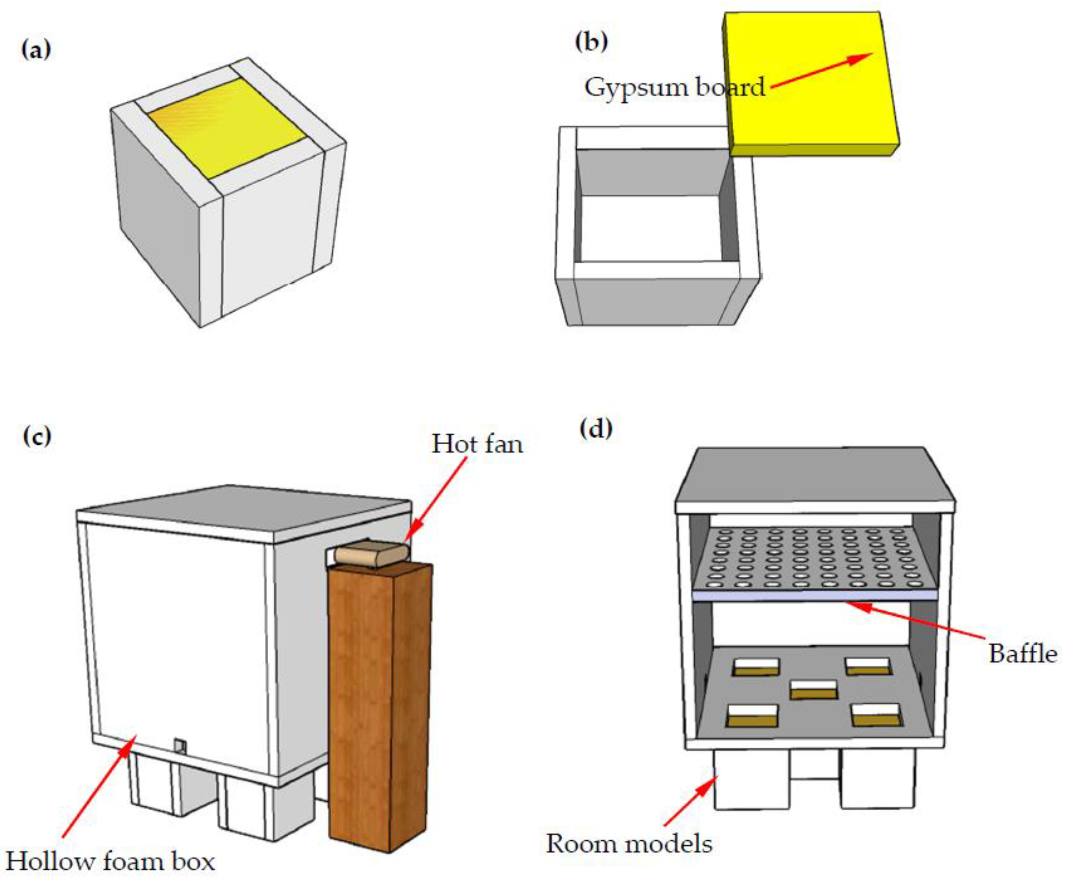
2.5.3. The Testing of Thermo-Regulated Performance

The thermal-regulated performance of the gypsum-based composite with different DP and CF contents was studied using self-designed room models. Five test room samples were made, and each consisted of six panels out of which five were made up of foam boards with a thickness of 45 mm, while the top panel was made with a gypsum-based composite. The size of the models was 290 mm × 290 mm × 285 mm with an internal dimension of 200 mm × 200 mm × 200 mm (as shown in Figure 1a,b). The dimensions of the gypsum panels were 200 mm × 200 mm × 40 mm. A thermocouple (Type K resolution ±0.3 °C) connected to a data-logger was placed in the center of the room model to record the temperature variation during the heating and cooling processes.
A hollow foam box with dimensions of 1000 mm × 1000 mm × 1000 mm and connected with a hot fan was used to create a stable temperature environment as shown in Figure 1c,d. A baffle, consisting of 64 evenly distributed holes each with a diameter of 60 mm (Figure 1d), was placed at a position of 400 mm below the top of the foam to create uniform heat flow. Five identical square openings with sizes of 200 mm × 200 mm at the bottom of the foam box were made, allowing the heat flow through the test panels, as shown in Figure 1d. This setup could enable the room models to be tested under the same experimental conditions. The ambient temperature was maintained at approximately 18 °C during the test, and each room model was heated for 170 min by the hot fan and then cooled down for another 220 min. The inner temperature readings of the room models were recorded and compared.

3. Results and Discussion

3.1. Characterization of the DP Composite

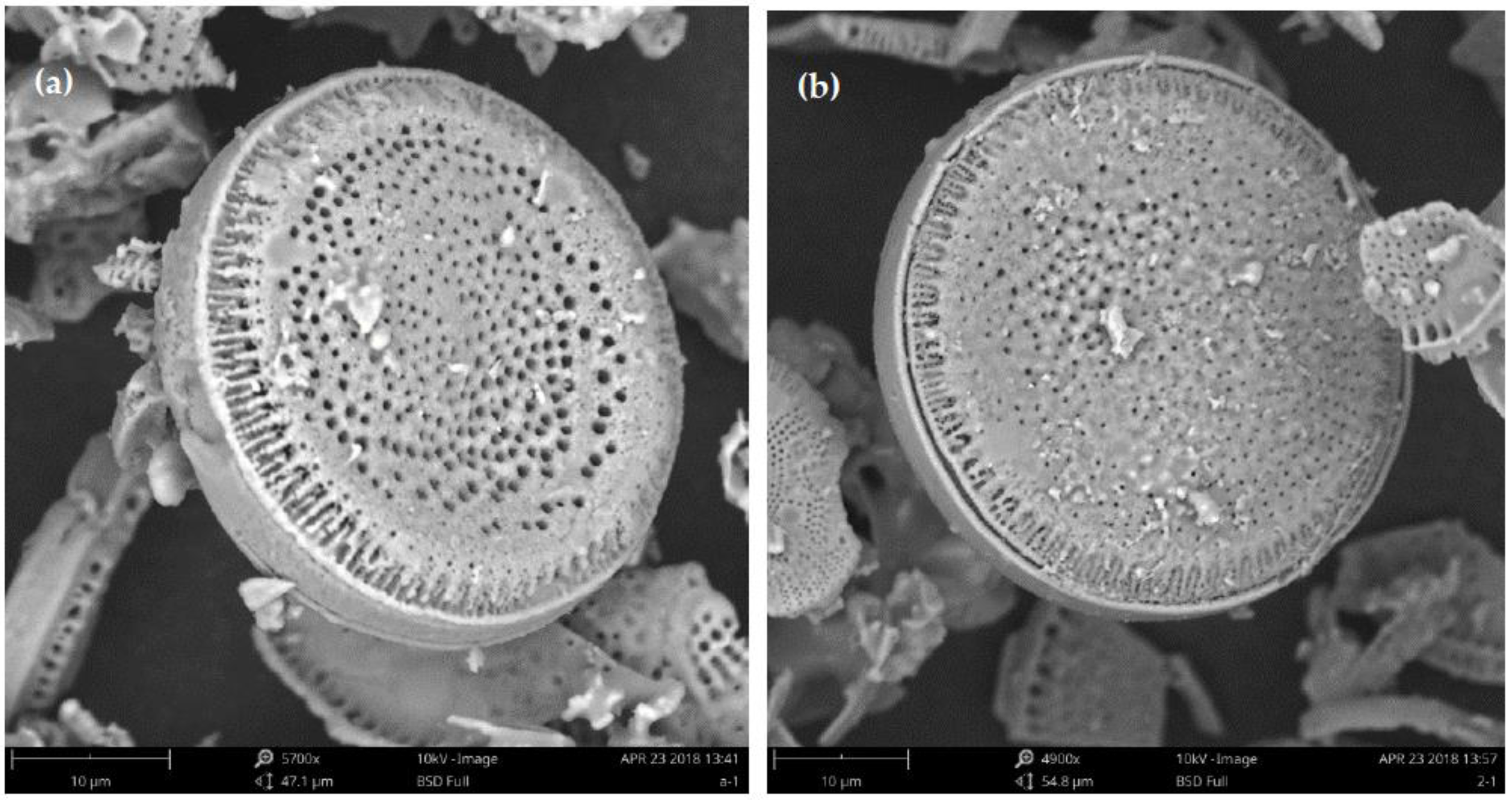
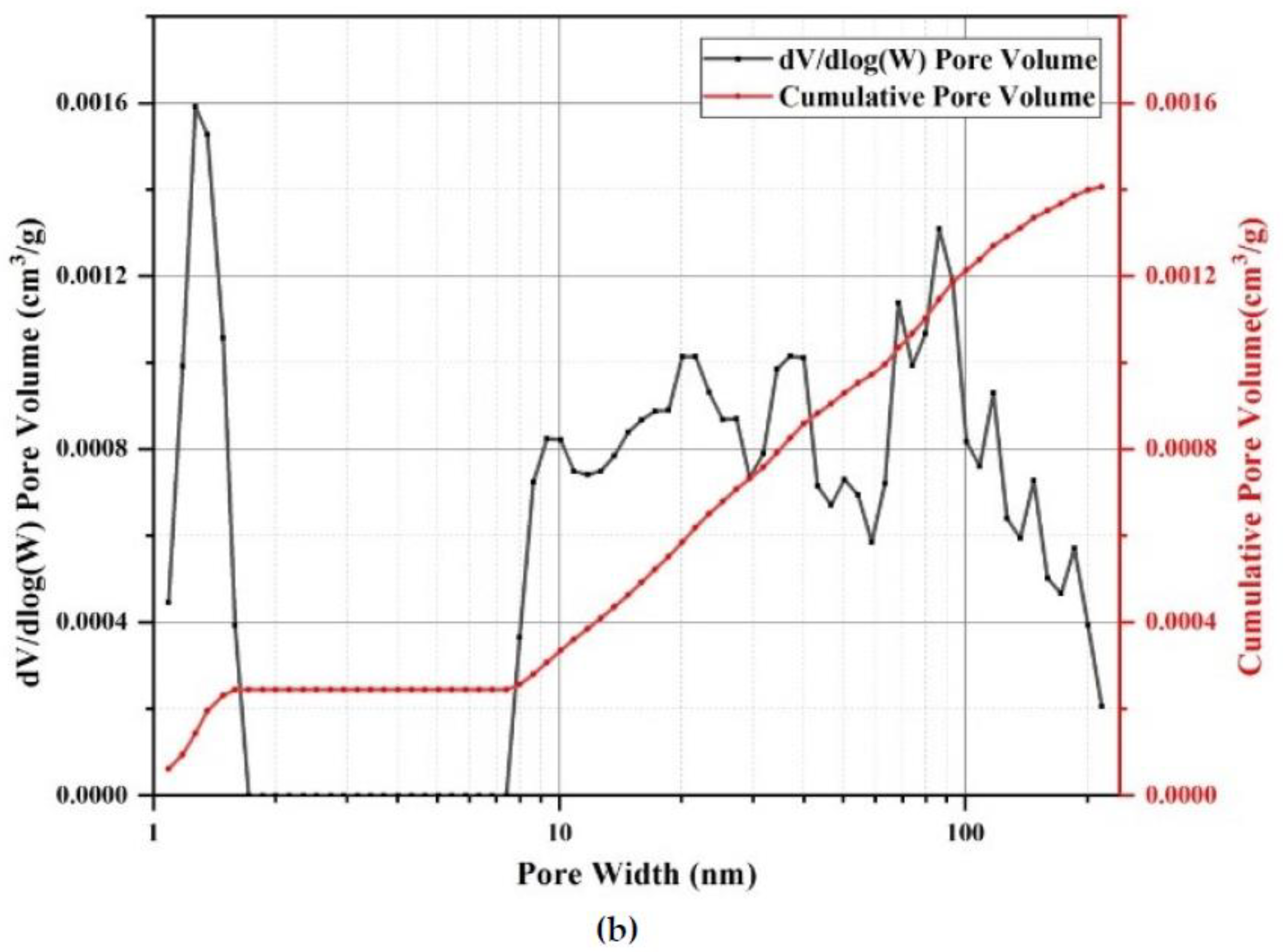
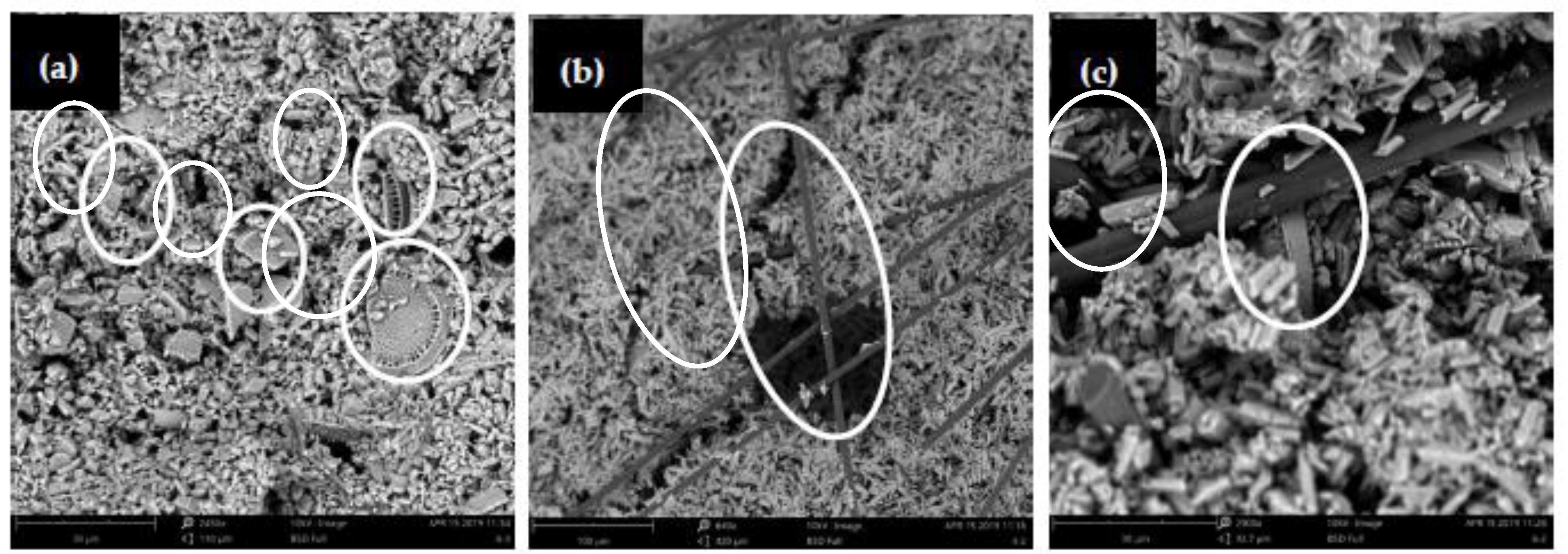
3.1.1. Microstructure of the Diatomite and DP Composite

As shown in Figure 2a, the diatomite exhibited a disc-shaped structure with many unconnected pores on its surface, while some of the pores were blocked by impurities. Figure 2b shows the microscopic morphology of diatomite after adsorbing the paraffin, in which the number and size of pores were significantly reduced compared with the pure diatomite. It can be inferred that the pores were filled up by paraffin. The relative pressure (P/P0) range of 0.4–0.8, as shown in Figure 3a, can be attributed to the capillary condensation during mesoporous adsorption, which shows that the majority of pores were mesopores [37]. Besides this, it can be seen from Figure 3b that the pore size of diatomite was generally below 220 nm, and the macropores (larger than 50 nm), mesopores (2–50 nm) and micropores occupied 17.26%, 48.66% and 34.08% of the total volume, respectively. Due to the significant amounts of mesopores and micropores, it can be stated that the absorption capacity of diatomite is high enough to store paraffin, as these pore structures have a high surface tension and capillary force.

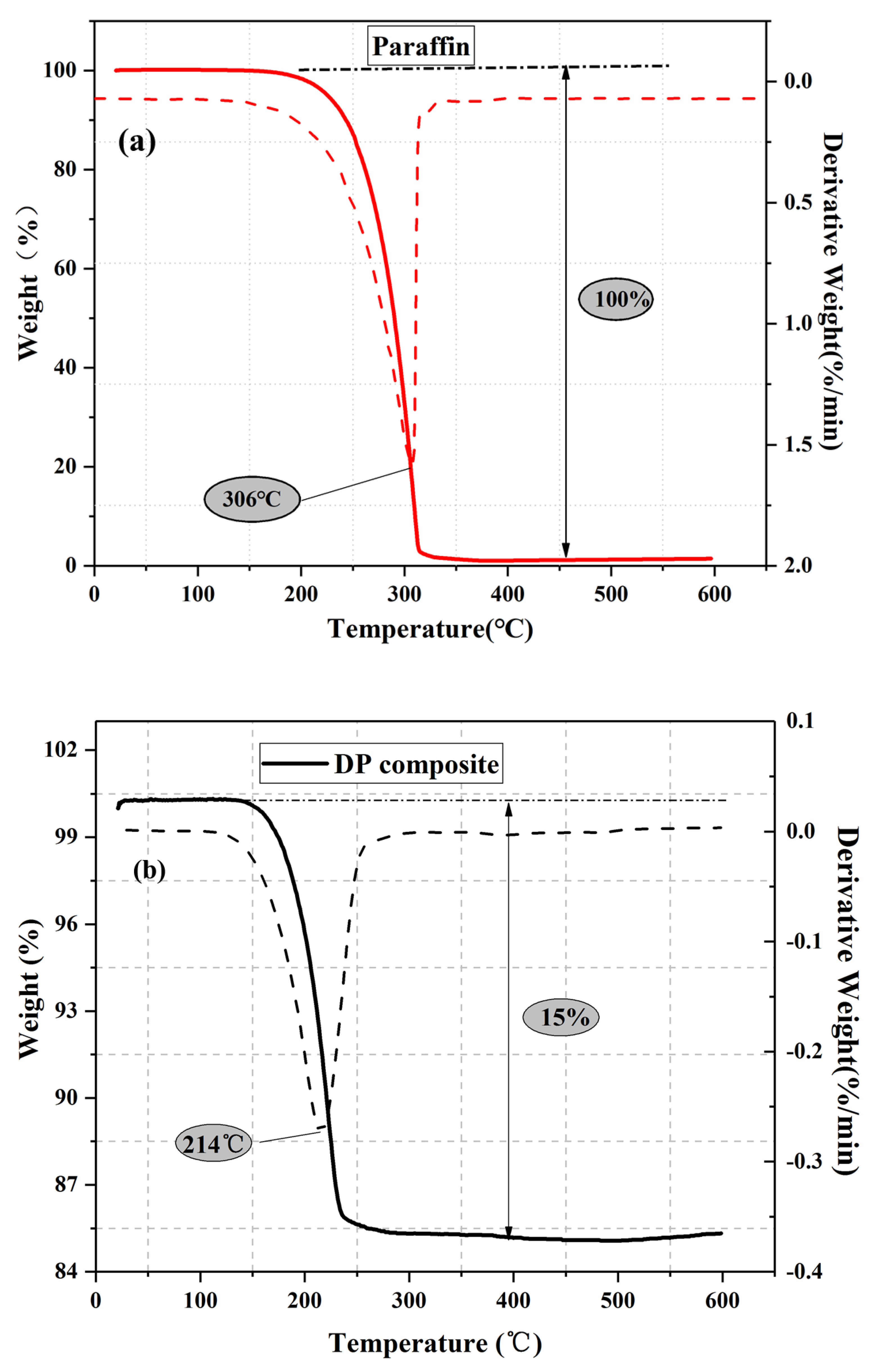
3.1.2. Thermo-Physical Properties of the DP Composite

Figure 4 shows the DSC curves of paraffin and the DP composite. The melting and solidification temperatures of paraffin were 21.75 °C and 19.85 °C, and the corresponding thermal latent heat values were 110.7 J/g and 121.6 J/g, respectively. The melting and solidification temperatures of the DP composite were 22.94 °C and 21.75 °C, and the corresponding latent heat values were 13.75 J/g and 18.75 J/g, respectively. According to Equation (1), we can calculate that the impregnation ratio of paraffin in the DP composite was 14%. These results are consistent with those of Guo et al. [24]. In their study, the paraffin was encapsulated by diatomite and high-density polyethylene to prepare SSPCM, and the melting and solidification enthalpy were approximately 14.75 J/g and 16.95 J/g, respectively.
It is worth noting that the melting temperature of DP is higher than that of pure paraffin. This might be related to the special pore structure and natural convection of paraffin. For pure paraffin, when the ambient temperature is higher than the melting temperature of pure paraffin, the paraffin surrounding and in contact with the environment will melt at first, and then the heat will flow to the unmelted paraffin by the driving force of natural convection, which could accelerate the melting of the pure paraffin. However, when the paraffin distributes evenly in the pores of diatomite, the flow of the paraffin is limited, especially in the unconnected pores, so the natural convection phenomenon is greatly weakened when paraffin is stored in the unconnected pores of diatomite [38].
Figure 5 shows the TGA curves of paraffin and DP. The paraffin began to decompose at around 180 °C and then volatilized completely at 315 °C. In contrast, the decomposition of DP occurred at temperatures ranging from 160 °C to 230 °C. The DP composite was more sensitive to temperature change during the heating process than the pure paraffin due to the higher thermal conductivity of DP. Although the DP has a lower decomposition temperature, it still meets the requirements of thermal stability for practical applications. According to the results shown in Figure 5b, the content of paraffin within DP was approximately 15 wt. %, which is close to the result of DSC (14 wt. %).

3.1.3. Chemical Structure of the DP Composite

Figure 6 shows the FT-IR curves of paraffin, diatomite and DP. Paraffin shows obvious absorption peaks at positions of 718 cm−1, 1466 cm−1, 1473 cm−1, 2849 cm−1 and 2918 cm−1. The absorption peak at 718 cm−1 is related to the rocking vibration of CH2 [39]. The asymmetric stretching vibration of the C = O functional group causes a peak at 1466 cm−1, and the peak at 1473 cm−1 is related to the asymmetric stretching vibration of the CH2 group [30]. The weak absorption peaks at 2345 cm−1 and 2461 cm−1 are caused by the CO2 antisymmetric stretching mode [40], which is affected by the atmospheric CO2, and the absorption peaks at 2849 cm−1 and 2918 cm−1 are ascribed to the stretching vibrations of CH2 and CH3, respectively [30]. Diatomite has four distinct absorption peaks at 455 cm−1, 791 cm−1, 1092 cm−1, and 3444 cm−1, and the first three are related to the bending vibration of Si-O (455 cm−1), the bending vibration of Si-O-H (791 cm−1), and the asymmetric stretching vibration of Si-O-Si (1092 cm−1), respectively [25,41]. The broadband of 3444 cm−1 corresponds to the vibration of the O-H mode in the physical adsorption of H2O, and the bending vibration of the water molecules retained in the diatomaceous silica matrix [42]. The absorption peaks of DP distribute at positions of 455 cm−1, 791 cm−1, 1092 cm−1, 1465 cm−1, 2354 cm−1, 2850 cm−1 and 2916 cm−1, which are contained within the peaks of paraffin or diatomite. This indicates that there is only a simple physical adsorption between paraffin and diatomite. Therefore, the DP composite is chemically compatible.

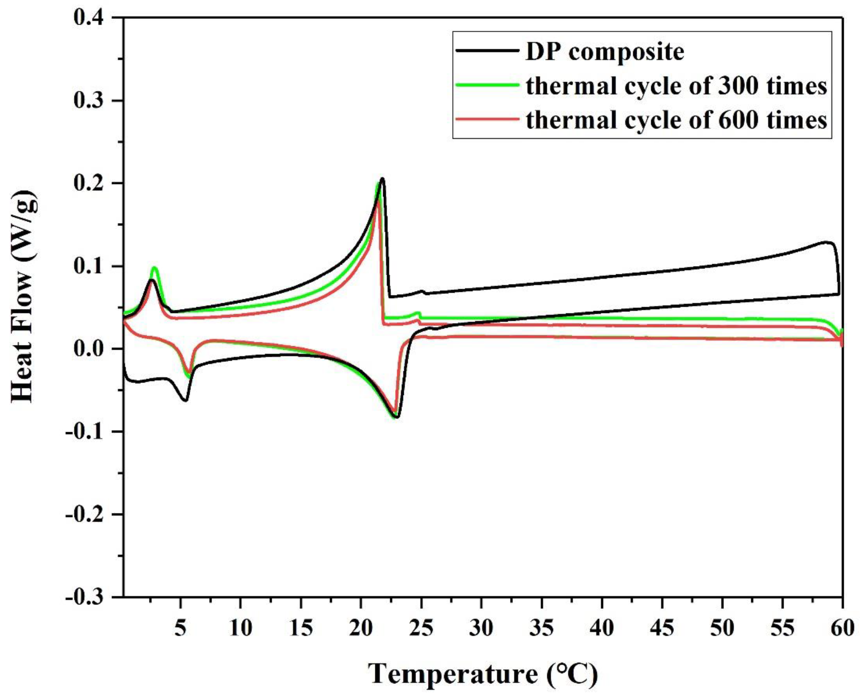
3.1.4. Thermal Cycle Test

Figure 7 and Table 3 show that the changes in the phase change temperature and enthalpy of DP after 300 cycles and 600 cycles are not significant. It can be seen that the melting temperature and solidification temperature of DP were basically the same before and after the thermal cycles, and that the average thermal latent heat value decreased by 0.79 J/g only. This indicates that the newly prepared DP is thermally stable and reliable over a long period of time, and is considered a good potential candidate for practical application.

3.2. Mechanical Properties of the DP/Gypsum Composite

Figure 8 shows the compressive strength results of all samples at 7 days. The compressive strength of the control mix (G-C) was 18.80 MPa. When 10% and 20% DP was added, the compressive strengths of the G-10%DP and G-20%DP samples decreased by 3.7% and 10.6%, respectively, when compared to the control (G-C). Although the flexural strength of G-10%DP is higher than the control (see Figure 9), it seems that the strength of gypsum generally decreased with increasing DP content. This may be due to the change in the microstructure of the materials. Figure 10 shows the microstructure of the composite materials. As shown in Figure 10a, DP is a discontinuous phase in the gypsum matrix, while diatomite is a porous material (see Figure 2). Additionally, the interfaces between diatomite and gypsum are weak. Therefore, the mechanical strengths of DP/gypsum decreased with the increase in DP content.
CF, with high tensile modulus values ranging from 230 to 500 GPa, can improve the mechanical properties of the DP/gypsum composites. When 1 wt. % carbon fiber was added, the compressive strengths of G-10%DP-1%CF and G-20%DP-1%CF increased by 29.8% and 9.0%, respectively, compared to the control (G-C). The effect of CF on flexural strength is much more significant. As seen in Figure 9, the flexural strengths of G-10%DP-1%CF and G-20%DP-1%CF increased by 176.0% and 56.0%, respectively, when compared to the control. This remarkable improvement is mainly due the high strength and toughness of CF, as well as its pull-out effect on the gypsum matrix that restrains the crack development. Specifically, as shown in Figure 10b,c, the CF, with an average diameter of 7 μm and length of 3 mm, can cross the pores or defects (<100 μm) that exist in the cement matrix, and thus it is able to restrain the crack development and separation under high tension and compression strengths. According to the test results, CF is considered effective in enhancing the mechanical properties of DP/gypsum, and the G-10%DP-1%CF composite displayed the best mechanical properties among the samples tested.

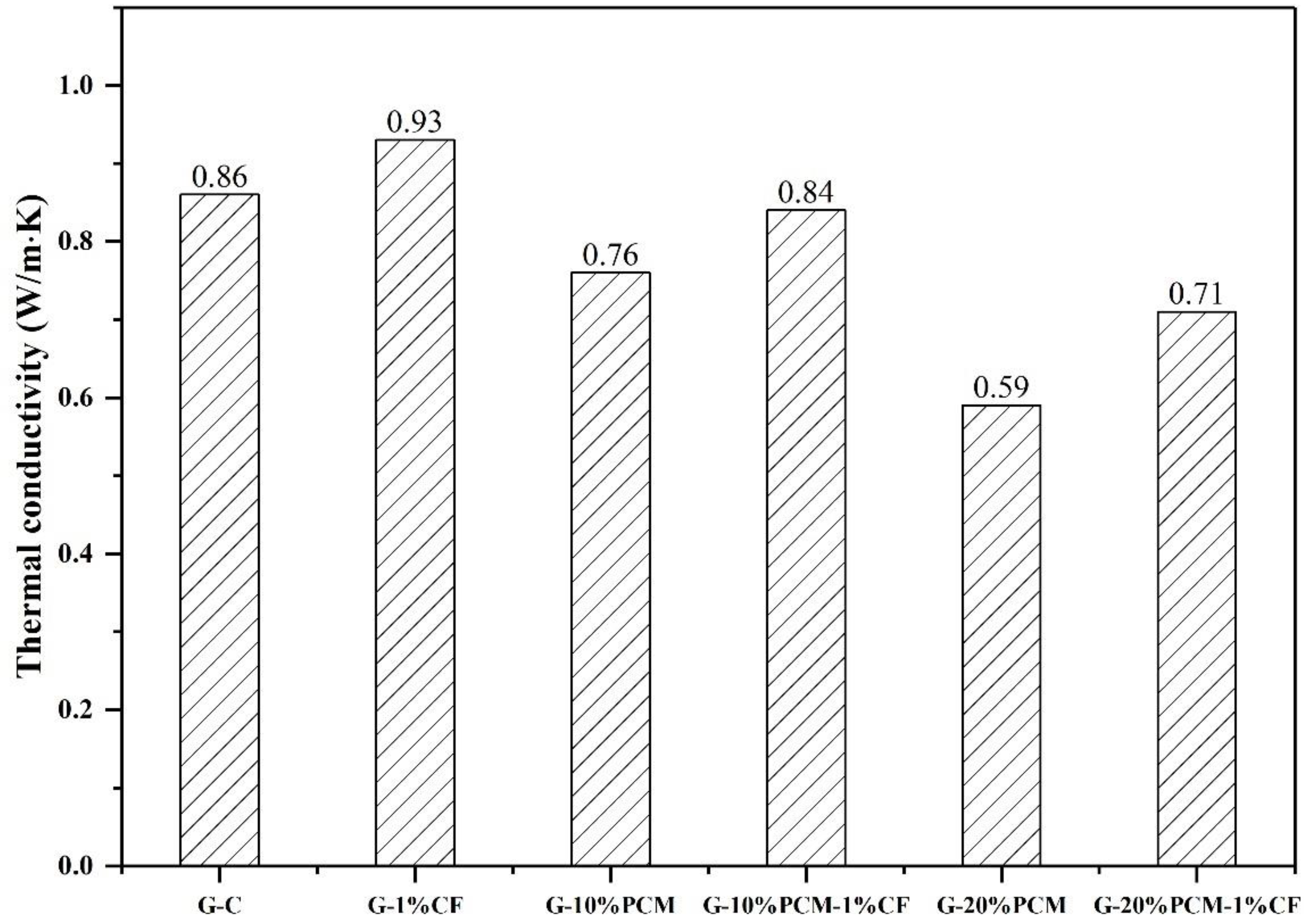
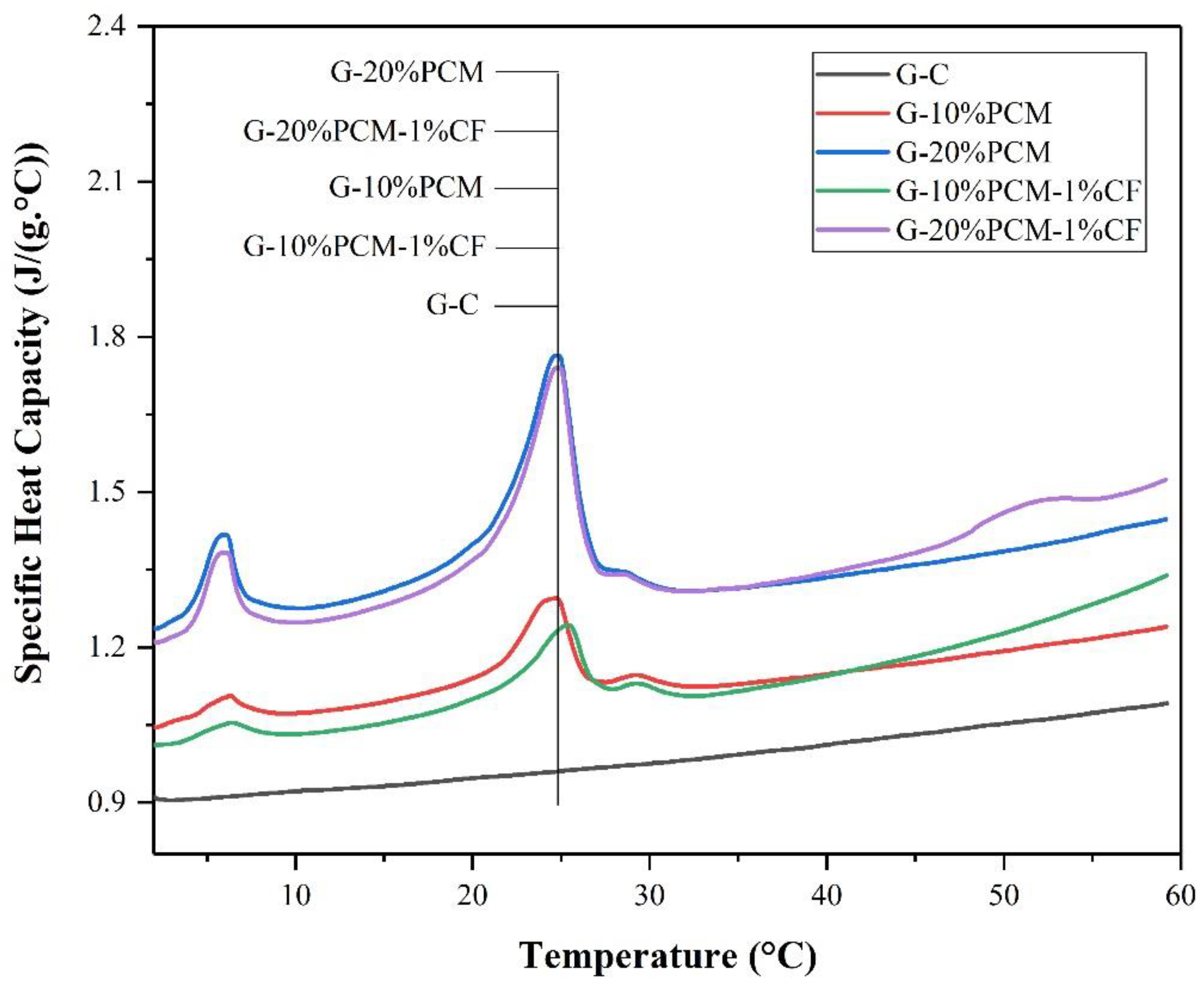
3.3. Thermal Conductivity, Density and Specific Heat Capacity of the DP/Gypsum Composites

Figure 11 shows the thermal conductivity of pure gypsum and DP/gypsum composites. The thermal conductivity of pure gypsum was 0.86 W/(m·K). The thermal conductivity of the DP/gypsum composites decreased as the proportion of DP increased. When 10% and 20% DP were added, the thermal conductivity of G-10% DP and G-20% DP decreased to 0.76 W/(m·K) and 0.59 W/(m·K), respectively. This is due to the fact that the thermal conductivity of DP (less than 0.40 W/(m·K)) [43,44,45] is much lower than that of the pure gypsum. However, the addition of 1% CF can increase the thermal conductivity of G-10% DP-1% CF and G-20% DP-1% CF by 10.5% and 20.3%, respectively, compared to the corresponding samples without CF. There are two main reasons for the improvement in thermal conductivity: First, the CF can improve the overall thermal conductivity of the composites. Second, the CF were well dispersed and inter-connected in the gypsum matrix, thus offering more channels for heat transfer [46]. Similar results can be found in the literature. In the research of Cheng et al. [47], the thermal conductivity of a beeswax–tetradecanol/expanded perlite composite increased from 0.443 W/(m·K) to 1.245 W/(m·K) because of the addition of 2% CF. Besides this, Huang et al. [48] incorporated 5% CF into an acetyl alcohol/high density polyethylene composite, and the resulting thermal conductivity increased from 0.2125 W/(m·K) to 0.4719 W/(m·K). Furthermore, with the increase in DP addition, the density of the gypsum decreased, as shown in Figure 12. When incorporating 20 wt. % DP, the density of gypsum decreased from 1902.3 kg/m3 to 1626.7 kg/m3. Therefore, the use of diatomite/paraffin/gypsum composites can also reduce the weight of the whole building. Figure 13 demonstrated that the specific heat capacity increased along with the addition of DP. This is due to the higher specific heat capacity of the incorporated DP in comparison to pure gypsum. Specifically, the specific heat capacities of G-C, G-10% DP, G-10% DP-1% CF, G-20% DP and G-20% DP-1% CF were 0.93 J/(g·°C), 1.10 J/(g·°C), 1.05 J/(g·°C), 1.31 J/(g·°C) and 1.28 J/(g·°C) at 15 °C, respectively. At 35 °C, the values were 0.99 J/(g·°C), 1.13 J/(g·°C), 1.12 J/(g·°C), 1.32 J/(g·°C) and 1.31 J/(g·°C), accordingly.

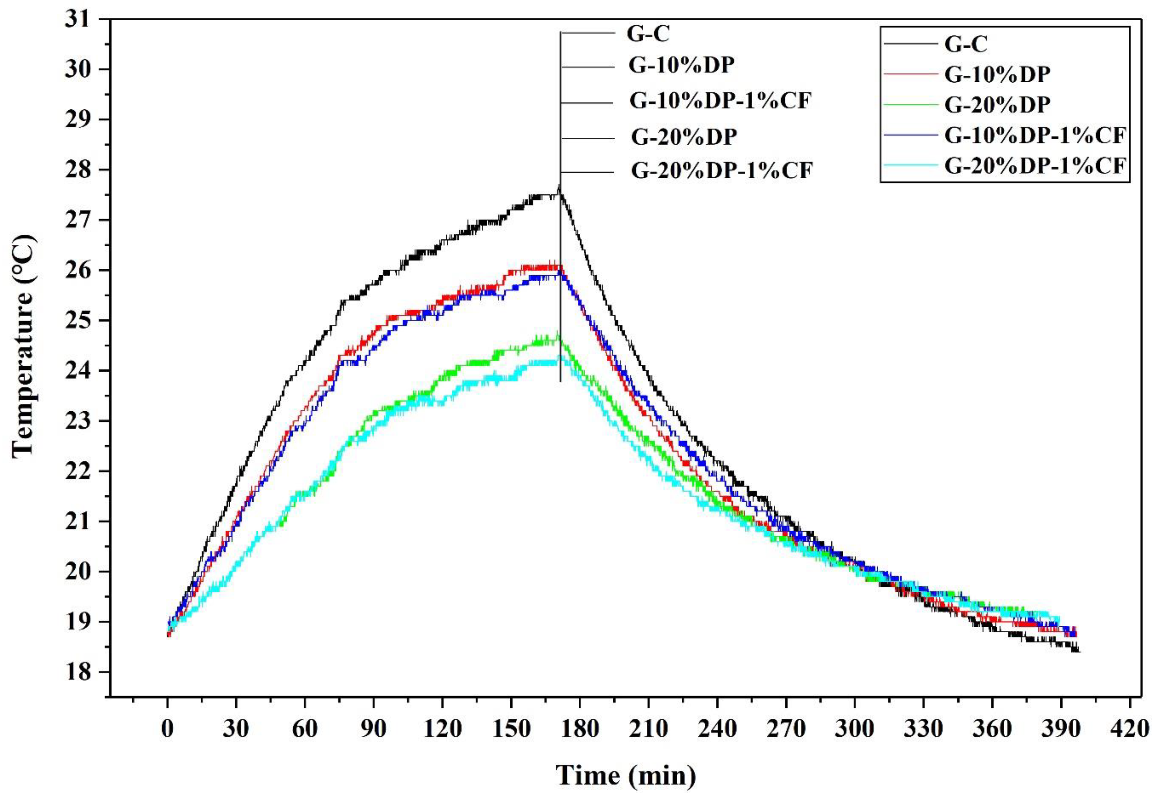
3.4. Thermo-Regulated Performance of the DP/Gypsum Composite

Figure 14 illustrates the indoor temperature variations of different room models. When the room models were heated for 2.83 h, the maximum indoor temperature of the control model (G-C) was 27.4 °C. However, the highest indoor temperatures of the G-10% DP and G-20% DP models were 25.9 °C and 24.5 °C, reducing by 1.5 °C and 2.9 °C, respectively. Obviously, the indoor temperature decreased as the DP content increased. Nevertheless, when 1 wt. % carbon fiber was added, the peak temperature of G-10% DP-1% CF was 25.7 °C, reducing by 1.7 °C compared to the control, while the maximum indoor temperature of G-20% DP-1% CF was 24.3 °C, which is 3.1 °C lower than that of the control room.
As shown in the schematic diagram of Figure 15, the reasons for the reductions in indoor temperatures are summarized as follows: (1) Once the outdoor temperature exceeded the phase change temperature of paraffin, the PCM began to melt and absorb heat, so the heat passing through the gypsum panel could be reduced. This in turn caused the indoor temperature to rise slowly, and resulted in a drop in the maximum indoor temperature; (2) CF greatly improved the thermal conductivity of DP/gypsum and the heat transfer of the PCM.
Although the DP used in this study has a small impregnation ratio (15%), it could help improve the thermo-regulation performance by reducing the indoor temperature by 3.1 °C. The application of DP within walls and roofs could not only reduce energy consumption, but also shift peaks in electricity consumption, contributing to the economic benefits and CO2 emission reduction.

3.5. Feasibility Analysis

3.5.1. Economic Feasibility

According to data from the 2019 Shenzhen Municipal Bureau of Statistics, the average housing area of every person in Shenzhen city of China was 21.12 m2, while the average area that required air conditioning was approximately 43 m2 for a household of four family members. The National Refrigeration Department announced that the typical power of an air conditioner was 3000W for an area from 42 m2 to 52 m2. Given the weather conditions in Shenzhen, air conditioners are normally required in the months from April to November, and are expected to operate for a period of 16 h per day. However, an air conditioner is usually intermittently operated, so the empirical operating time was then assumed to be 40–50% of the usage time. Therefore, the annual power consumption by air conditioning per household was calculated as 3000 × 16 × 6 × 30 × 0.45/1000 = 3888 kW·h, or 648 kW·h monthly (during the 6 months of operating). The Shenzhen Power Grid Department announced that the cost of electricity would be 0.98 RMB/kW·h when the electricity consumption in the current month exceeds 600 kW·h. As a result, the air conditioning cost per household would be 3810.24 RMB/year.
Based on the household’s annual air conditioning power consumption, the daily power consumption would be 10.65 kW·h/day or 38.35 MJ/day. To absorb 38.35 MJ of heat, 2360 kg of DP is required, comprising 354 kg paraffin, 2006 kg diatomite, 20,060 kg gypsum and 200.6 kg CF. The market prices of paraffin, diatomite, gypsum and CF were 8.5 RMB/kg, 2.2 RMB/kg, 0.5 RMB/kg and 85.0 RMB/kg, respectively. It is worthwhile to point out that the efficiency of DP depends on temperature and weather conditions, so it was assumed that the PCM had a working efficiency of 50% [49]. Moreover, according to the authors’ experience, it will take 30 working days to prepare 2660 kg DP, and 3 working days to fabricate DP/gypsum. The labor cost is approximately 300 RMB/day, and thus the total labor cost is RMB 9900. Based on the above discussions, the payback period of applying structural–functional integrated energy storage gypsum board was 23.31 years, as indicated in Table 4, which is much less than the service life of the building, and it is considered suitable to be used as building components.

3.5.2. Practical Feasibility

According to the Global and Chinese Gypsum Board Industry Report (2014–2016) [50], the use of global gypsum board was up to 12.2 billion square meters in 2013, and the demand continues to grow. Therefore, the development of this kind of structural–functional integrated energy storage gypsum board is very promising. Besides this, the energy storage gypsum board mainly consists of paraffin, diatomite, gypsum and carbon fiber. These materials are easily accessible and inexpensive, so they can meet the application requirements.

3.5.3. Environmental Feasibility

From the above discussions, it is clear that each household would save 3888 kWh of power consumption every year by using the energy storage gypsum board. According to the study of Mittal [51], the saving of each unit of electrical power is equivalent to saving 0.4 kg standard coal, and the emission of 0.95 kg carbon dioxide, 0.272 kg dust, 0.007 kg sulfur dioxide and 0.003 kg nitrogen oxide. Therefore, using the energy storage gypsum board can help each household to save a total of 1555.2 kg of standard coal, and prevent the emissions of 1057.54 kg dust, 3693.6 kg carbon dioxide, 27.22 kg sulfur dioxide and 11.66 kg nitrogen oxide annually. Clearly, it is highly feasible to apply the energy storage gypsum boards in buildings with respect to their environmental benefits.

4. Conclusions

In this study, a gypsum-based PCM composite reinforced with carbon fiber, a kind of structural–functional integrated energy storage building material, was developed. According to the results, the following conclusions are drawn:
(1)
From the SEM and N2 adsorption, it can be seen that diatomite with a porous structure could provide enough space for storing paraffin. The impregnation ratio of paraffin in the diatomite was approximately 15 wt. %;
(2)
Based on the thermo-physical characteristics, thermal stability, chemical structure and thermal reliability of diatomite/paraffin, it can be concluded that the diatomite/paraffin composite is suitable for practical application;
(3)
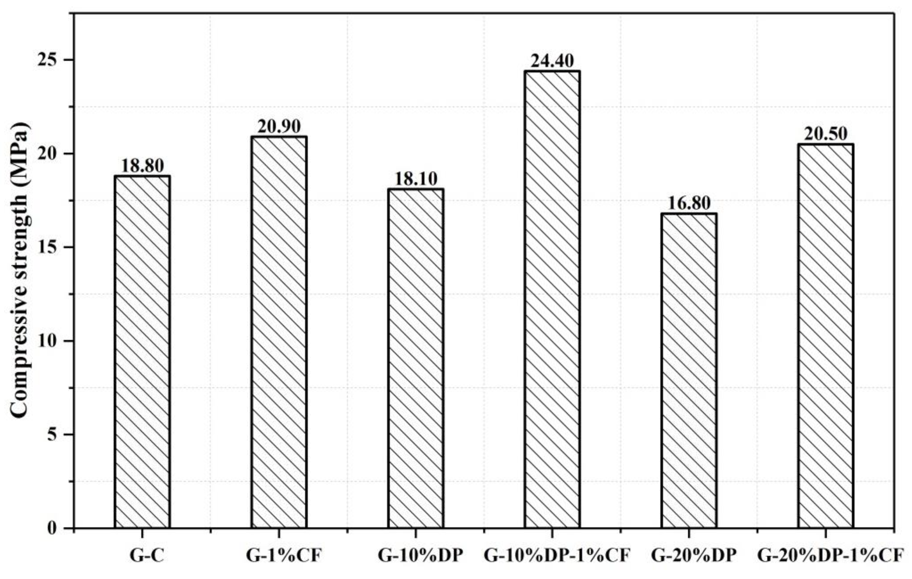
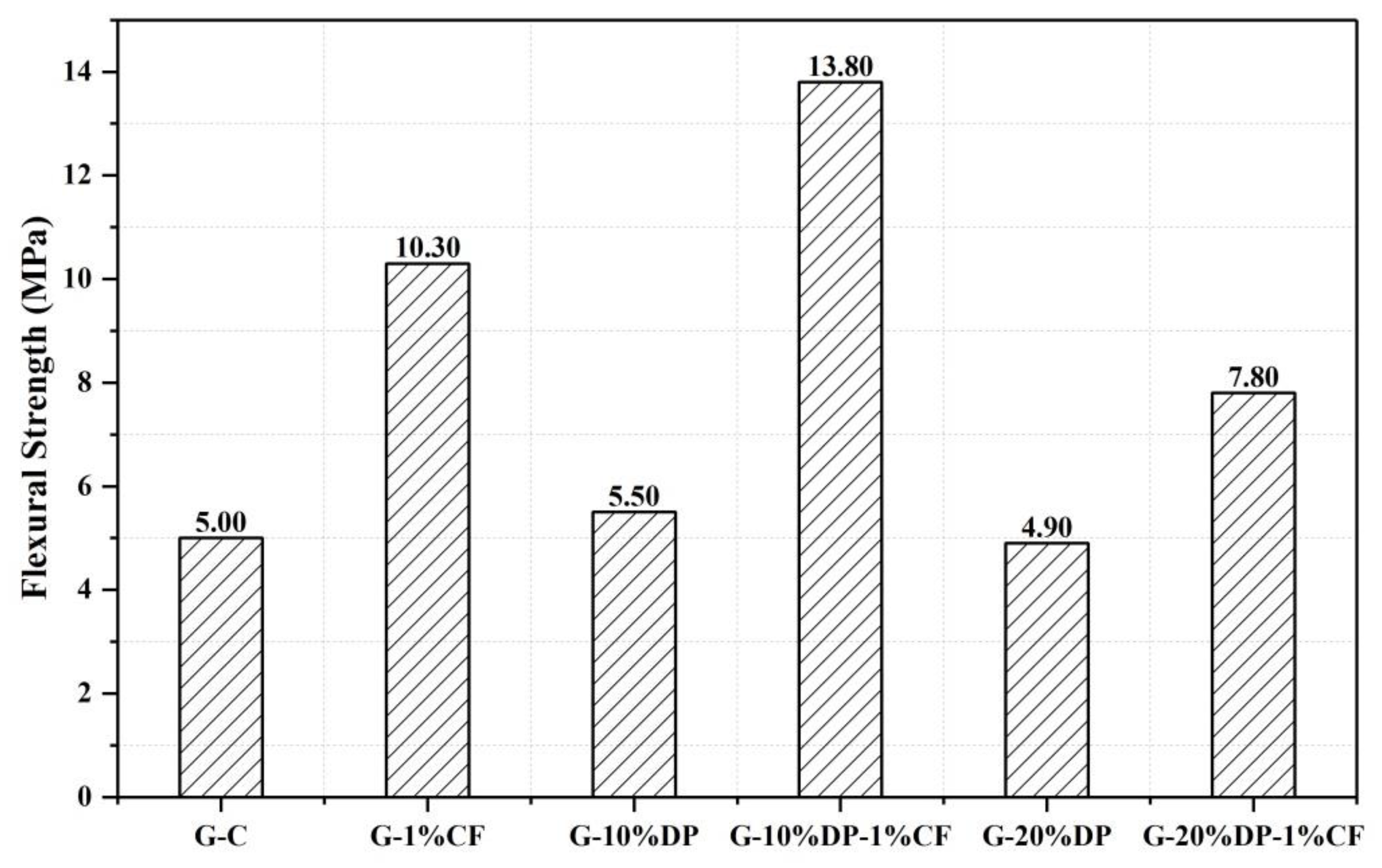
The compressive strength of gypsum decreased slightly with the increase in diatomite/paraffin content. However, adding 1% CF could increase the compressive and flexural strengths of G-10% and DP-1% CF by 29.8% and 176.0%, respectively, when compared to the control. These improvements are due to the pull-out effect of carbon fiber restraining the cracks’ development;
(4)
When 1 wt. % CF was added into the composite, the thermal conductivity of G-20% DP increased to 0.71 W/(m·K) from 0.59 W/(m·K), with an increase of 20.3%;
(5)
The indoor temperature of the room model with a G-20% DP-1% CF composite panel was 3.1 °C lower than that of the control. In general, the composite showed an excellent thermo-regulated performance;
(6)
The payback period of applying CF-reinforced diatomite/paraffin/gypsum in residential buildings was only 23.31 years, which is much less than the average life span of building (60 years).

Author Contributions

B.Z. did the experiments and data analysis and wrote part of this paper. H.Y. did the experiments and data analysis and wrote part of this paper. T.X. did the data analysis. W.T. wrote part of this paper. H.C. provided the original ideas and did the experiments and data analysis. All authors have read and agreed to the published version of the manuscript.

Funding

The work presented in this paper was fully supported by a grant from Natural Science Foundation of China (51925804).

Data Availability Statement

Data sharing is not applicable to this article.

Acknowledgments

The authors would like to thank the Shenzhen University to support this research.

Conflicts of Interest

The authors declare no conflict of interest.

Abbreviations

PCMPhase change material
SSPCMShape-stabilized phase change material
CFCarbon fibers
DPDiatomite/paraffin
FESEMField emission scanning electron microscope
BETBrunauer Emmett Teller
DSCDifferential scanning calorimetry
TGAThermogravimetric analysis
FT-IRFourier transform infrared spectrometer

References

  1. Choi, S.H.; Park, J.; Ko, H.S.; Karng, S.W. Heat penetration reduction through PCM walls via bubble injections in buildings. Energy Convers. Manag. 2020, 221, 113187. [Google Scholar] [CrossRef]
  2. Mizan, M.H.; Ueda, T.; Matsumoto, K. Enhancement of the concrete-PCM interfacial bonding strength using silica fume. Constr. Build. Mater. 2020, 259, 119774. [Google Scholar] [CrossRef]
  3. Fateh, A.; Borelli, D.; Weinläder, H.; Devia, F. Cardinal orientation and melting temperature effects for PCM-enhanced light-walls in different climates. Sustain. Cities Soc. 2019, 51, 101766. [Google Scholar] [CrossRef]
  4. Marin, P.; Saffari, M.; de Gracia, A.; Zhu, X.; Farid, M.M.; Cabeza, L.F.; Ushak, S. Energy savings due to the use of PCM for relocatable lightweight buildings passive heating and cooling in different weather conditions. Energy Build. 2016, 129, 274–283. [Google Scholar] [CrossRef] [Green Version]
  5. Cunha, S.; Lima, M.; Aguiar, J.B. Influence of adding phase change materials on the physical and mechanical properties of cement mortars. Constr. Build. Mater. 2016, 127, 1–10. [Google Scholar] [CrossRef] [Green Version]
  6. Memon, S.A.; Lo, T.Y.; Cui, H.; Barbhuiya, S. Preparation, characterization and thermal properties of dodecanol/cement as novel form-stable composite phase change material. Energy Build. 2013, 66, 697–705. [Google Scholar] [CrossRef]
  7. Powała, K.; Heim, D. Paraffin Permeability of Synthetic Gypsum Binders Modified by Individual Polymers. Latv. J. Phys. Tech. Sci. 2019, 56, 47–56. [Google Scholar] [CrossRef]
  8. Qian, Z.; Shen, H.; Fang, X.; Fan, L.; Zhao, N.; Xu, J. Phase change materials of paraffin in h-BN porous scaffolds with enhanced thermal conductivity and form stability. Energy Build. 2018, 158, 1184–1188. [Google Scholar] [CrossRef]
  9. Ramakrishnan, S.; Wang, X.; Sanjayan, J.; Wilson, J. Thermal performance assessment of phase change material integrated cementitious composites in buildings: Experimental and numerical approach. Appl. Energy 2017, 207, 654–664. [Google Scholar] [CrossRef]
  10. Cellat, K.; Tezcan, F.; Beyhan, B.; Kardaş, G.; Paksoy, H. A comparative study on corrosion behavior of rebar in concrete with fatty acid additive as phase change material. Constr. Build. Mater. 2017, 143, 490–500. [Google Scholar] [CrossRef]
  11. Novais, R.M.; Ascensão, G.; Seabra, M.P.; Labrincha, J.A. Lightweight dense/porous PCM-ceramic tiles for indoor temperature control. Energy Build. 2015, 108, 205–214. [Google Scholar] [CrossRef]
  12. Hajjar, A.; Mehryan, S.A.M.; Ghalambaz, M. Time periodic natural convection heat transfer in a nano-encapsulated phase-change suspension. Int. J. Mech. Sci. 2020, 166, 105243. [Google Scholar] [CrossRef]
  13. Ramakrishnan, S.; Wang, X.; Sanjayan, J.; Wilson, J. Assessing the feasibility of integrating form-stable phase change material composites with cementitious composites and prevention of PCM leakage. Mater. Lett. 2017, 192, 88–91. [Google Scholar] [CrossRef]
  14. Abden, M.J.; Tao, Z.; Pan, Z.; George, L.; Wuhrer, R. Inclusion of methyl stearate/diatomite composite in gypsum board ceiling for building energy conservation. Appl. Energy 2020, 259, 114113. [Google Scholar] [CrossRef]
  15. Yang, H.; Memon, S.; Bao, X.; Cui, H.; Li, D. Design and Preparation of Carbon Based Composite Phase Change Material for Energy Piles. Materials 2017, 10, 391. [Google Scholar] [CrossRef] [PubMed] [Green Version]
  16. Mohseni, E.; Tang, W.; Wang, S. Development of thermal energy storage lightweight structural cementitious composites by means of macro-encapsulated PCM. Constr. Build. Mater. 2019, 225, 182–195. [Google Scholar] [CrossRef]
  17. Sukontasukkul, P.; Uthaichotirat, P.; Sangpet, T.; Sisomphon, K.; Newlands, M.; Siripanichgorn, A.; Chindaprasirt, P. Thermal properties of lightweight concrete incorporating high contents of phase change materials. Constr. Build. Mater. 2019, 207, 431–439. [Google Scholar] [CrossRef] [Green Version]
  18. Ryms, M.; Klugmann-Radziemska, E. Possibilities and benefits of a new method of modifying conventional building materials with phase-change materials (PCMs). Constr. Build. Mater. 2019, 211, 1013–1024. [Google Scholar] [CrossRef]
  19. Ali Memon, S.; Yiu Lo, T.; Shi, X.; Barbhuiya, S.; Cui, H. Preparation, characterization and thermal properties of Lauryl alcohol/Kaolin as novel form-stable composite phase change material for thermal energy storage in buildings. Appl. Therm. Eng. 2013, 59, 336–347. [Google Scholar] [CrossRef]
  20. Marske, F.; Silva, J.M.D.S.E.; Wehrspohn, R.B.; Hahn, T.; Enke, D. Synthesis of monolithic shape-stabilized phase change materials with high mechanical stability via a porogen-assisted in situ sol–gel process. Rsc Adv. 2020, 10, 3072–3083. [Google Scholar] [CrossRef] [Green Version]
  21. Zhang, X.; Kim, Y.; Kim, D.; Liu, M.; Erramuspe, I.B.V.; Kaya, G.B.; Wang, X.; Kim, T.; Via, B.K.; Cho, H. Shape-Stabilized Phase Change Material by a Synthetic/Natural Hybrid Composite Foam with Cell-Wall Pores. Acs Appl. Energy Mater. 2020. [Google Scholar] [CrossRef]
  22. Li, A.; Dong, C.; Dong, W.; Atinafu, D.G.; Gao, H.; Chen, X.; Wang, G. Hierarchical 3D Reduced Graphene Porous-Carbon-Based PCMs for Superior Thermal Energy Storage Performance. ACS Appl. Mater. Interfaces 2018, 10, 32093–32101. [Google Scholar] [CrossRef] [PubMed]
  23. Wen, R.; Zhang, X.; Huang, Z.; Fang, M.; Liu, Y.; Wu, X.; Min, X.; Gao, W.; Huang, S. Preparation and thermal properties of fatty acid/diatomite form-stable composite phase change material for thermal energy storage. Sol. Energy Mater. Sol. Cells 2018, 178, 273–279. [Google Scholar] [CrossRef]
  24. Guo, X.; Huang, Y.; Cao, J. Performance of a thermal energy storage composite by incorporating diatomite stabilized paraffin as phase change material. Energy Build. 2018, 158, 1257–1265. [Google Scholar] [CrossRef]
  25. Rao, Z.; Zhang, G.; Xu, T.; Hong, K. Experimental study on a novel form-stable phase change materials based on diatomite for solar energy storage. Sol. Energy Mater. Sol. Cells 2018, 182, 52–60. [Google Scholar] [CrossRef]
  26. Konuklu, Y.; Ersoy, O.; Gokce, O. Easy and industrially applicable impregnation process for preparation of diatomite-based phase change material nanocomposites for thermal energy storage. Appl. Therm. Eng. 2015, 91, 759–766. [Google Scholar] [CrossRef]
  27. Kastis, D.; Kakali, G.; Tsivilis, S.; Stamatakis, M.G. Properties and hydration of blended cements with calcareous diatomite. Cem. Concr. Res. 2006, 36, 1821–1826. [Google Scholar] [CrossRef]
  28. Jeong, S.-G.; Jeon, J.; Lee, J.-H.; Kim, S. Optimal preparation of PCM/diatomite composites for enhancing thermal properties. Int. J. Heat Mass Transf. 2013, 62, 711–717. [Google Scholar] [CrossRef]
  29. Qian, T.; Li, J. Octadecane/C-decorated diatomite composite phase change material with enhanced thermal conductivity as aggregate for developing structural–functional integrated cement for thermal energy storage. Energy 2018, 142, 234–249. [Google Scholar] [CrossRef]
  30. Xu, B.; Li, Z. Paraffin/diatomite/multi-wall carbon nanotubes composite phase change material tailor-made for thermal energy storage cement-based composites. Energy 2014, 72, 371–380. [Google Scholar] [CrossRef]
  31. Kuttah, D.; Sato, K. Review on the effect of gypsum content on soil behavior. Transp. Geotech. 2015, 4, 28–37. [Google Scholar] [CrossRef]
  32. Oliver, A. Thermal characterization of gypsum boards with PCM included: Thermal energy storage in buildings through latent heat. Energy Build. 2012, 48, 1–7. [Google Scholar] [CrossRef]
  33. Tang, F.; Su, D.; Tang, Y.; Fang, G. Synthesis and thermal properties of fatty acid eutectics and diatomite composites as shape-stabilized phase change materials with enhanced thermal conductivity. Sol. Energy Mater. Sol. Cells 2015, 141, 218–224. [Google Scholar] [CrossRef]
  34. Sarı, A.; Bicer, A.; Al-Sulaiman, F.A.; Karaipekli, A.; Tyagi, V.V. Diatomite/CNTs/PEG composite PCMs with shape-stabilized and improved thermal conductivity: Preparation and thermal energy storage properties. Energy Build. 2018, 164, 166–175. [Google Scholar] [CrossRef]
  35. Xu, G.; Leng, G.; Yang, C.; Qin, Y.; Wu, Y.; Chen, H.; Cong, L.; Ding, Y. Sodium nitrate – Diatomite composite materials for thermal energy storage. Sol. Energy 2017, 146, 494–502. [Google Scholar] [CrossRef]
  36. Cui, H.; Feng, T.; Yang, H.; Bao, X.; Tang, W.; Fu, J. Experimental study of carbon fiber reinforced alkali-activated slag composites with micro-encapsulated PCM for energy storage. Constr. Build. Mater. 2018, 161, 442–451. [Google Scholar] [CrossRef]
  37. Li, C.; Yu, H.; Song, Y.; Wang, M.; Liu, Z. A n-octadecane/hierarchically porous TiO2 form-stable PCM for thermal energy storage. Renew. Energy 2020, 145, 1465–1473. [Google Scholar] [CrossRef]
  38. Zou, D.; Ma, X.; Liu, X.; Zheng, P.; Hu, Y. Thermal performance enhancement of composite phase change materials (PCM) using graphene and carbon nanotubes as additives for the potential application in lithium-ion power battery. Int. J. Heat Mass Transf. 2018, 120, 33–41. [Google Scholar] [CrossRef]
  39. Xu, T.; Li, Y.; Chen, J.; Wu, H.; Zhou, X.; Zhang, Z. Improving thermal management of electronic apparatus with paraffin (PA)/expanded graphite (EG)/graphene (GN) composite material. Appl. Therm. Eng. 2018, 140, 13–22. [Google Scholar] [CrossRef]
  40. Kauffman, K.L.; Culp, J.T.; Goodman, A.; Matranga, C. FT-IR Study of CO2 Adsorption in a Dynamic Copper(II) Benzoate−Pyrazine Host with CO2−CO2 Interactions in the Adsorbed State. J. Phys. Chem. C 2011, 115, 1857–1866. [Google Scholar] [CrossRef]
  41. Yusan, S.; Korzhynbayeva, K.; Aytas, S.; Tazhibayeva, S.; Musabekov, K. Preparation and investigation of structural properties of magnetic diatomite nanocomposites formed with different iron content. J. Alloy. Compd. 2014, 608, 8–13. [Google Scholar] [CrossRef]
  42. Zhao, D. Adsorption of thorium(IV) on MX-80 bentonite: Effect of pH, ionic strength and temperature. Appl. Clay Sci. 2008, 41, 17–23. [Google Scholar] [CrossRef]
  43. Qian, T.; Li, J.; Min, X.; Guan, W.; Deng, Y.; Ning, L. Enhanced thermal conductivity of PEG/diatomite shape-stabilized phase change materials with Ag nanoparticles for thermal energy storage. J. Mater. Chem. A 2015, 3, 8526–8536. [Google Scholar] [CrossRef]
  44. Yu, H.; Li, C.; Zhang, K.; Tang, Y.; Song, Y.; Wang, M. Preparation and thermophysical performance of diatomite-based composite PCM wallboard for thermal energy storage in buildings. J. Build. Eng. 2020, 32, 101753. [Google Scholar] [CrossRef]
  45. Zhang, P.; Cui, Y.; Zhang, K.; Wu, S.; Chen, D.; Gao, Y. Enhanced thermal storage capacity of paraffin/diatomite composite using oleophobic modification. J. Clean. Prod. 2021, 279, 123211. [Google Scholar] [CrossRef]
  46. Wang, T.; Wang, S.; Geng, L.; Fang, Y. Enhancement on thermal properties of paraffin/calcium carbonate phase change microcapsules with carbon network. Appl. Energy 2016, 179, 601–608. [Google Scholar] [CrossRef]
  47. Cheng, F.; Wen, R.; Zhang, X.; Huang, Z.; Huang, Y.; Fang, M.; Liu, Y.g.; Wu, X.; Min, X. Synthesis and characterization of beeswax-tetradecanol-carbon fiber/expanded perlite form-stable composite phase change material for solar energy storage. Compos. Part A Appl. Sci. Manuf. 2018, 107, 180–188. [Google Scholar] [CrossRef]
  48. Huang, X.; Alva, G.; Liu, L.; Fang, G. Microstructure and thermal properties of cetyl alcohol/high density polyethylene composite phase change materials with carbon fiber as shape-stabilized thermal storage materials. Appl. Energy 2017, 200, 19–27. [Google Scholar] [CrossRef]
  49. Bao, X.; Tian, Y.; Yuan, L.; Cui, H.; Tang, W.; Fung, W.H.; Qi, H. Development of high performance PCM cement composites for passive solar buildings. Energy Build. 2019, 194, 33–45. [Google Scholar] [CrossRef]
  50. Available online: https://www.prweb.com/releases/gypsum-board-industry/report-2014-2016/prweb12155688.htm (accessed on 3 January 2021).
  51. Mittal, M.L.; Sharma, C.; Singh, R. Decadal emission estimates of carbon dioxide, sulfur dioxide, and nitric oxide emissions from coal burning in electric power generation plants in India. Environ. Monit. Assess. 2014, 186, 6857. [Google Scholar] [CrossRef]
Figure 1. The schematic diagram of thermo-regulated performance testing: (a) Room model; (b) Schematic diagram of room model; (c) Testing system; (d) Section of testing system.
Applsci 11 00468 g001
Figure 2. SEM images of (a) diatomite, and (b) diatomite/paraffin.
Applsci 11 00468 g002
Figure 3. N2 adsorption–desorption isotherm of diatomite: (a) isotherm linear plot, and (b) pore size distribution and cumulative pore volume.
Applsci 11 00468 g003aApplsci 11 00468 g003b
Figure 4. DSC curves of paraffin and diatomite/paraffin.
Applsci 11 00468 g004
Figure 5. TGA and derivative of the TGA (DTG) curves: (a) paraffin and (b) diatomite/paraffin.
Applsci 11 00468 g005
Figure 6. FT-IR spectra: (a) paraffin, (b) diatomite, and (c) diatomite/paraffin.
Applsci 11 00468 g006
Figure 7. DSC curves of diatomite/paraffin with thermal cycles of 0, 300 and 600 times.
Applsci 11 00468 g007
Figure 8. The compressive strength of the diatomite/paraffin/gypsum composites after 7 days curing.
Applsci 11 00468 g008
Figure 9. The flexural strength of the diatomite/paraffin/gypsum after 7 days curing.
Applsci 11 00468 g009
Figure 10. SEM images of microstructure of the composites: (a) the 20% diatomite/paraffin/gypsum; (b) gypsum with 1% carbon fiber; and (c) gypsum with 20% diatomite/paraffin and 1% carbon fiber.
Applsci 11 00468 g010
Figure 11. The thermal conductivity of diatomite/paraffin/gypsum composites.
Applsci 11 00468 g011
Figure 12. The density of diatomite/paraffin/gypsum composites.
Applsci 11 00468 g012
Figure 13. The specific heat capacity of diatomite/paraffin/gypsum composites.
Applsci 11 00468 g013
Figure 14. The curves of the indoor temperature variation of five small house models.
Applsci 11 00468 g014
Figure 15. The schematic diagram of the thermo-regulating mechanism of different diatomite/paraffin panels.
Applsci 11 00468 g015
Table 1. Characteristics of the main materials used in this study.
Materials NameProduct No.Physical Properties
Paraffin25#Melting temperature: ~22 °C
Latent heat: ~120 J/g
GypsumSZ-GY2000Setting time: 8–10 min
Expansion: less 0.08%
DiatomiteSD 3001#Bulk density: 0.34–0.65 g/cm3
Specific surface area: 40–65 m2/g
Pore volume: 0.45–0.98 m³/g
Density: 0.47 g/cm³
CF700 SC-12KTensile strength: ~4.9 GPa
Tensile modulus: ~230 GPa
Density: 1.8 g/cm3
CMCC804619Viscosity: 400–800 mPa.s
Table 2. The mix proportion of diatomite/paraffin/gypsum (DP/gypsum).
No.Gypsum (g)Water (g)DP (g)CF (g)CMC (g)
G-C36001300----3.6
G-1% CF36001300--363.6
G-10% DP36001300360--3.6
G-20% DP36001300720--3.6
G-10% DP-1% CF36001300360363.6
G-20% DP-1% CF36001300720363.6
Table 3. The phase change temperature and enthalpy after thermal cycles of 0, 300 and 600 times.
Thermal Cycle TimesTMΔHMTFΔHFAverage Enthalpy
((ΔHM + ΔHF)/2)
022.94 °C13.75 J/g21.75 °C18.75 J/g16.25 J/g
300 times22.77 °C15.05 J/g21.45 °C17.36 J/g16.21 J/g(−0.04 J/g)
600 times22.79 °C14.02 J/g21.37 °C16.89 J/g15.46 J/g(−0.79 J/g)
Table 4. The cost–benefit analysis of the application of structural–functional integrated energy storage gypsum board.
The Cost of Using Structural–Functional Integrated Energy Storage Gypsum Board (RMB)The Use Efficiency of DP Panel (%)Electricity Consumption per Year (RMB)Static Payback Period (Year)
Total cost of paraffin Total cost of diatomiteTotal cost of gypsum Fabrication cost Total cost 0.53810.2423.31
354 × 8.52006 × 2.220,060 × 0.533 × 30034,503.2
Publisher’s Note: MDPI stays neutral with regard to jurisdictional claims in published maps and institutional affiliations.

