Abstract
Phased arrays are widely used in different fields, such as broadcasting, radar, optics, and space communications. The principle of phased arrays is to generate a directed signal from a large number of antennas to be steered at any desired angle. This, however, increases the probability of defective elements in an array. Faulty elements in an array cause asymmetry and result in increased sidelobe levels which rigorously distort the radiation pattern. Increased sidelobe radiation wastes energy and can cause interference by radiating and receiving signals in unintended directions. Therefore, it is necessary to find a method that can provide accuracy in the radiation pattern transmitted or received in the presence of failed element(s) in an array. This paper compares the few available optimization methods, namely, simulated annealing (SA), Genetic Algorithm (GA), Particle Swarm Optimization (PSO), and Pattern Search (PS) methods. For each method, various types of failures were examined, and the most suitable techniques to recover the far-field radiation are recommended. The optimization is then carried out by selecting the optimal weights of the remaining working elements in the planar array. The optimized radiation pattern’s efficiency was evaluated by comparing the Signal to Noise Ratio (SNR) value of the optimized radiation with reference and failed radiation patterns. The PSO method showed a better performance compared to all the other methods in reducing the failed radiation pattern’s SNR value. In various types of failure tests, this method reduced the failed radiation pattern’s SNR from 1 to 10 dB. This method also successfully produced a radiation pattern that closely matches the reference pattern before any failed element(s) are presented in the array. The life cycle of a planar array system with faulty elements can be increased by optimizing the remaining active elements in the array with the PSO method. It also reduces the cost of restoring and replacing the failed elements in an array regularly. This approach also prevents near-field measurement that requires complicated processes using costly equipment.
1. Introduction
Phased array antennas are used to form directed signals that can be steered at the desired angle. Some specific applications of phased arrays include broadcasting, radar, optics, and space communication. The current trend in the telecommunication industry with Massive-Input-Massive-Output (MIMO) uses a large number of multiple antennas at the transmitter and receiver ends. Its base station is equipped with tens to hundreds of antennas in a single antenna array. The usage of phased arrays in space communication is also increasing [1].
This large array distribution in a system increases the probability of more antenna system elements failing, and the failures are unavoidable [2]. The failed elements cause the array to lose its symmetry, resulting in a distorted radiation pattern with increased sidelobe levels, weakening null depth and null shift [1]. This causes transmitters to waste energy and cause interference to other equipment by radiating signals in unwanted directions. While in receivers, the noise level is increased by receiving interfering signals. This will reduce the efficiency of the transmitter and the receiver.
Research on failure elements in arrays has existed since the end of the 20th century and the beginning of the 21st century because of its continuous usage in various fields. Now it is regaining its attention due to its mass usages in wireless and communication systems and other fields. The need for failure correction techniques is still necessary.
Replacing the failed element with a new element is not a possible solution for applications such as space platforms, where it is complex, time-consuming, and expensive. So, optimization-based far-field radiation pattern correction methods with remaining active elements in the array are being researched [3,4,5,6].
Recent research on correcting failed radiation patterns are with grey wolf optimizer hybridized with an interior point algorithm [7], Improved Particle Swarm Optimization with Wavelet Mutation [8], Particle Swarm Optimization (PSO) and Bacteria Foraging Optimization (BFO) [5], Whale Optimization Algorithm (WOA) and Chaotic Whale Optimization Algorithm (CWOA) [9], and Backtracking Search Optimization [10]. However, this research focuses on the linear array, which consists of a smaller number of elements in an array. Failed pattern correction with the planar array is limited. Some available research uses the Simulated Annealing Technique [11], Artificial Neural Network with Hopfield network [12], and Particle Swarm Optimization [13]. In study [11], the number of faulty elements in an array is very little, while the current communication systems have more probability of element failure in an array. Other than that, reference [13] has investigated a 5 × 5 planar array with 2 to 20 element failures in the array.
Most of the papers in the literature used a meta-heuristic search for restoring the radiation pattern. However, each method has its disadvantages, such as solutions converge prematurely, easily fall into a local optimum, and adequate parameter tuning [14]. An optimization algorithm developed varies case by case. Similarly, optimization methods developed for linear arrays and smaller array sizes will not be suitable for a large planar array.
This paper compares four different optimization methods; simulated annealing (SA), genetic algorithm (GA), particle swarm optimization (PSO), and pattern search (PS) method, and proposes a method that is suitable for large planar array radiation pattern correction at the end of the paper. A failed radiation pattern is corrected by optimizing the weights of the remaining working elements in the array. The method will improve the overall efficiency of any system with a planar array and reduce the cost of repairing and replacing the failed element(s) in an array. This method also avoids near fields measurement, which involves complex processes and uses expensive equipment.
2. Design Methodology
The design scheme presented in this paper is divided into two parts; the first part is developing a planar array model with an 8 × 8 element array. Secondly, four different optimization processes were applied to the planar array model, described in Section 2.2. A flowchart of the whole process is shown in Figure 1.
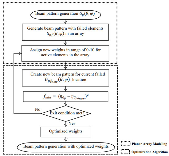
Figure 1.
Flowchart of failed radiation pattern correction methodology.
This paper illustrates a suitable optimization method for failed planar array radiation patterns where the optimization is done in MATLAB through simulation. All the simulation was done with a 64-bit operating system that contains an Intel(R) Core (TM) i7-4790 CPU processor and 16 GB installed memory. This simulation is for research purposes only. To be implemented in real-time, the optimization can be programmed in C language and processed in real-time on Digital Signal Processor (DSP) embedded processor platform, which will make the process faster. This simulation has the limitation of computer capability and software limitations.
2.1. Problem Formulation
2.1.1. Array Beam Pattern Generation
Beam pattern is also known as spatial signal processing. It transmits and receives sound waves in the desired direction by phase shift and time delay. It is well known for its advantage of high gain, focused directivity, reduced interference, and improved device ability, producing better signal quality than omnidirectional signals. The phased array beamforming method [15] is used to generate a beam pattern with elements, an ultrasonic frequency of , and the speed of sound in air at °C is , the inter-element distance avoiding grating is:
The array factor beam pattern was normalized with equal amplitudes of . Planar array beam pattern is formed by the superposition of two-beam patterns, on the x-axis and on the y-axis. The beamforming output for the planar array pattern is given in (3).
where
and
and = −90:1:90, are the scanning angle of x and y dimensions;
γ is steering angle;
, uniform weight on each element;
is the inter-element distance between array elements;
, Array elements, and is the index.
Figure 2 shows elements in an array with uniform inter-element distance [15].
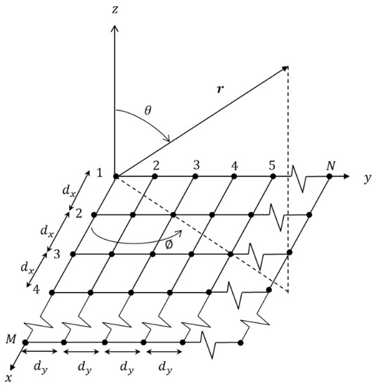
Figure 2.
elements in an array with uniform inter-element distance.
2.1.2. Failed Beam Pattern Generation
Failed array weights, and , are used to simulate failed beam patterns. Failed element weights in and were assigned as zero instead of one in and . For this purpose, elements from Rows 4 and 7 (24 elements) in the array are failed in an 8 × 8 element array. The beam pattern formulation of failed elements is as (8).
Figure 3 shows the planar array with Row 4 and Row 7 failed elements. The failed elements in the figure below are not shaded, while the functional elements are shaded.
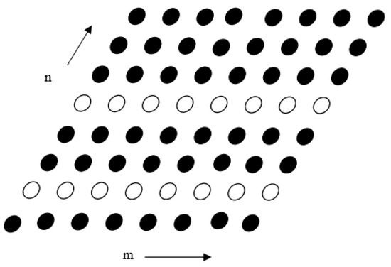
Figure 3.
Failed elements in a planar array with non-uniform inter-element distance.
2.1.3. Performance Measure of the Radiation Patterns
The gain performance of the radiation patterns is measured with SNR, . It is set to be the ratio of the main beam above the −3 dB, to the side lobes as (9) of each radiation pattern.
2.2. Optimization Algorithms
Lately, metaheuristic algorithms have been used in numerous fields, such as engineering, economics, politics, and management, to solve complex real-life problems [16]. A proper balance between intensification and diversification elements is required to solve real-life problems effectively [17]. A carefully chosen optimization algorithm for a specific cause can effectively solve many nonlinear optimization problems [18].
In this paper, four different optimization methods, SA [19], GA [20], PSO [21], and PS method [22], were used to optimize the remaining working element in the planar array. An optimization method that produces SNR similar to the initial radiation pattern was proposed at the end of the paper for a planar array failed radiation pattern correction.
To optimize the weights, an objective function is created. In the objective function, SNR is calculated with (8) for a reference radiation pattern , and a current optimized pattern . The optimization will compare both SNR values and minimize the objective function. The objective function is defined as (10):
The planar array weights, and , are vector quantities that require optimization techniques. Minimization in the objective function will return optimized weights of remaining working elements in the array that can generate an optimized beam pattern of the array in the presence of failure elements.
3. Results & Discussion
3.1. Planar Array Modeling Results
The methodology developed was to examine a planar array with 8 × 8 and 6 × 6 elements with interelement distance. Equation (3) was used to generate a beam pattern of reference radiation pattern without any failed elements in an array. Figure 4 shows an example of a reference radiation pattern for 8 × 8 elements.
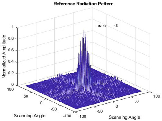
Figure 4.
Radiation Pattern of an 8 × 8 planar array (reference radiation pattern) in a mesh grid representation.
Next, the failed radiation beam pattern is generated with Equation (8) by designating the failed element’s weight as zero. It is assumed that the failed element(s) do not contribute to the radiation pattern. In this analysis, the probability of faulty elements is fixed to a maximum of 25 elements (varies on case basis) in an 8 × 8 array and 12 elements for a 6 × 6 array. Figure 5a shows 25 elements failed in a random location radiation pattern and its failed radiation pattern in Figure 5b.
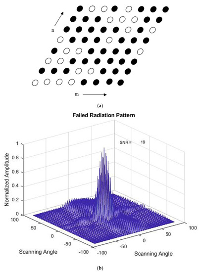
Figure 5.
(a) 25 Failed Elements at 8 × 8 planar array. (b) Failed Radiation Pattern of an 8 × 8 planar array with 25 failed elements in the array.
3.2. Optimization Algorithm Results
Then, the failed radiation pattern was restored by optimizing the remaining active elements of the array. The optimization methods described in Section 2.2 were applied to the failed radiation pattern following the optimization flow. New weights for the remaining working element were assigned to calculate SNR for the current radiation pattern. The objective function is evaluated as in (10). The objective function minimizes the error between the current radiation pattern and the reference radiation pattern without any failed elements in the array. The iteration continues until the optimization meets the exit condition where the optimization stops.
An example of results from applying the PS optimization method to 25 failed element radiation patterns is shown in Figure 6 and the optimized weights are shown in Table 1.
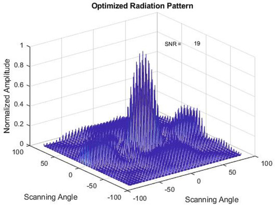
Figure 6.
Optimized radiation pattern with the PS method.

Table 1.
Optimized weights for random 25 element failure with the PS method.
Next, the optimization methods were implemented for eight different types of failure as listed in Table 2 to analyze the efficiency of the methods towards different types of failure in 8 × 8 and 6 × 6 planar arrays, respectively.

Table 2.
Failure types for 8 × 8 and 6 × 6 planar arrays.
The results of the 8 × 8 planar array in Rows 4 and 7 that failed for all four optimization methods are shown. Figure 7a–c represents the initial, failed, and optimized radiation patterns of the SA method. The corresponding optimized weights are shown in Table 3. In this case, the optimized radiation pattern has a higher SNR value compared to failed radiation pattern. This method could not meet the objective where optimized weights in a planar array should generate an optimized radiation pattern that matches the reference radiation pattern with a lower SNR value than the failed radiation pattern SNR.
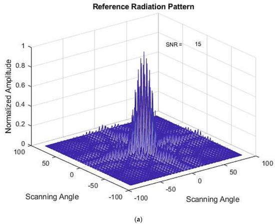
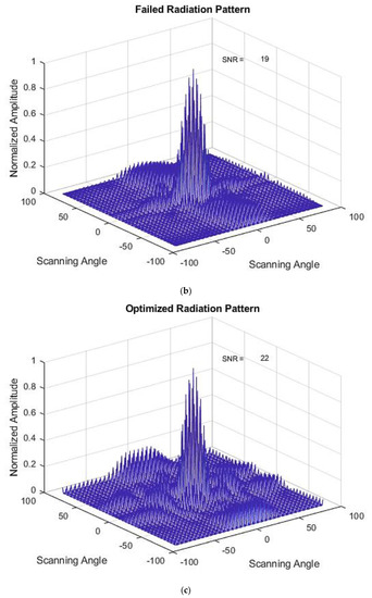
Figure 7.
(a) Initial Radiation Pattern for the SA Method. (b) Failed Radiation Pattern for the SA Method. (c) Optimized Radiation Pattern for the SA Method.

Table 3.
Optimized weights for Type 1 failure for the SA method.
Results of the GA method with a similar type of failure are shown in Figure 8a–c. The optimized weights for this Type 1 failure are shown in Table 4. A lower SNR value was observed at the optimized radiation pattern, but the main lobe level is compromised. For failure Types 2, 3, 6, and 8, this method performed less accurately, as described in Table 2.
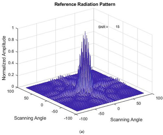
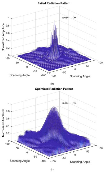
Figure 8.
(a) Initial Radiation Pattern for the GA method. (b) Failed Radiation Pattern for the GA method. (c) Optimized Radiation Pattern for the GA method.

Table 4.
Optimized weights for Type 1 failure for the GA method.
The PSO method results for the same type of failure are shown in Figure 9a–c. The optimized weights using this method are shown in Table 5. Here, the method has matched the SNR value of the optimized radiation pattern with the reference radiation pattern. The main lobe level is also maintained. From an SNR value of 19 in the failed radiation pattern, the method has successfully reduced the value to 15 in the optimized radiation pattern.
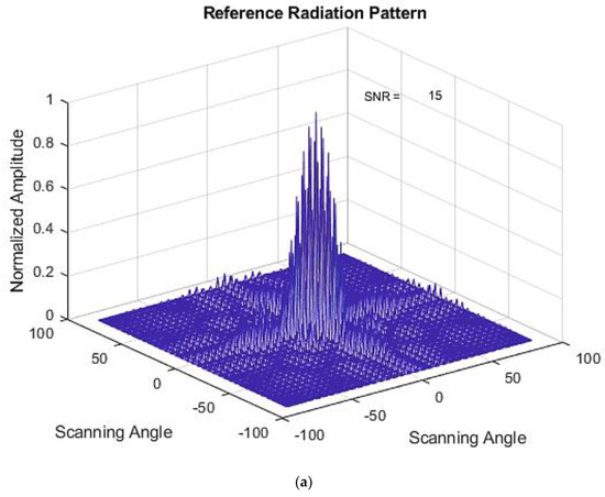
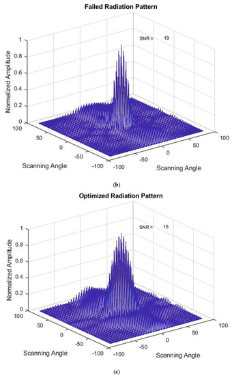
Figure 9.
(a) Initial Radiation Pattern for the PSO method. (b) Failed Radiation Pattern for the PSO method. (c) Optimized Radiation Pattern for the PSO method.

Table 5.
Optimized weights for Type 1 failure for the PSO method.
Next, the results of a similar type of failure with the PS method are shown in Figure 10a–c. The optimized weights for this Type 1 failure are shown in Table 6. This method has also reduced the failed radiation pattern SNR value after optimization without compromising the main lobe level. The failed SNR value of 19 was reduced to an SNR value of 17 for the optimized radiation pattern.
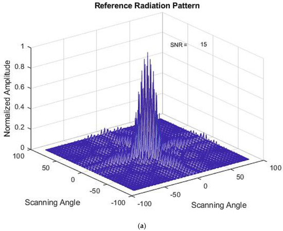
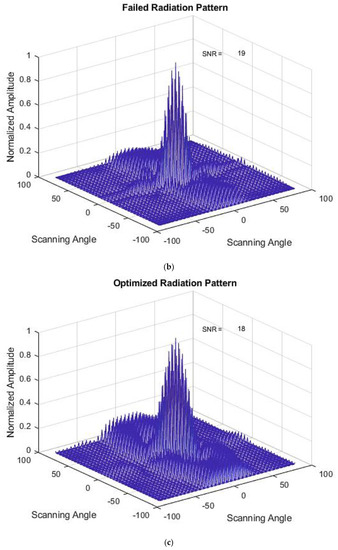
Figure 10.
(a) Initial Radiation Pattern for the PS method. (b) Failed Radiation Pattern for the PS method. (c) Optimized Radiation Pattern for the PS method.

Table 6.
Optimized weights for Type 1 failure for the PS method.
Table 7 shows a compilation of reference, failed, and optimized SNR values for eight types of failures with two different array sizes, namely 8 × 8 and 6 ×6 planar arrays for all four optimization methods.

Table 7.
Results of various types of failures for four different optimization methods of 8 × 8 and 6 × 6 planar arrays.
The results show that not all of the optimization methods chosen are suitable for correcting failed planar array radiation patterns. For SA, the optimized radiation pattern’s SNR is higher than failed radiation pattern for all the failure types for 8 × 8. Similar results are observed for the 6 × 6 planar array.
GA in the 8 × 8 planar array for failure Type 2 and Type 3 could not optimize the failed radiation pattern. The SNR value of the optimized radiation pattern was higher than the failed radiation pattern’s SNR for both cases. Likewise, a higher SNR value was observed in the optimized radiation pattern for failure Type 6 and Type 8 in the 6 × 6 array.
Both PSO and PS methods successfully optimized SNR values lower than the failed SNR values for all types of failure. PSO, in particular, has reached SNR values almost similar to the reference SNR values in most cases and provides a 1 to 10 dB reduction depending on failure types. The PS method successfully provides lower SNR values at the optimized radiation pattern by reducing 2 to 5 dB from the failed SNR.
The main difference between PSO and GA is that GA is a discrete technique while PSO is a continuous technique. Aside from generating new solutions during their search explorations, PSO searches for the best solution space while GA searches via crossover [23]. This may lead to PSO providing the best solution for a problem. On the other hand, pattern search uses a directed move in a search space, while GA uses a sample search space and many generations. PS finds the best performance for a comparatively smaller search space and less computing time than GA [24].
In terms of time for the optimizations to converge, SA took 1439.593 s, PS took 1520.216 s, GA took 8120.882 s, and PSO took 9079.376 s on average. SA and GA took shorter time periods to converge, but the methods failed to meet the objective. On the other hand, the methods that provide expected results, PS and PSO, have a huge difference among them in terms of the time to converge. For real-time implementation, the optimization can be programmed in the ‘C’ language and processed in real-time on a Digital Signal Processor (DSP) embedded processor platform. This will make the process faster. The PSO method is suggested for better accuracy in matching the SNR value of the reference radiation pattern.
This summarizes that the PSO method provides a better solution for failed planar array radiation pattern correction with the highest SNR reduction with a higher time to converge. It is also shown that the weights of the remaining working elements in a planar array can be optimized to produce a radiation pattern with a reduced SNR value to enhance the efficiency of a system with the presence of faulty elements in an array without compromising main lobe levels.
4. Conclusions
The objective of this research was to investigate the performance of different optimization methods for selecting the most suitable techniques for recovering far-field radiation. The findings indicate that the SA and GA methods are not suitable for failed planar array radiation pattern correction. The PSO method provided the highest SNR reduction (1 to 10 dB) among all the methods. The PS method also provided an ideal solution for this case where it managed to reduce 2 to 5 dB of failed SNR values. The PSO and PS methods took 9079.376 s and 1520.216 s, respectively, to converge. Next, users can compare cost and time factors upon applying these optimization methods in real life to correct failed planar array correction.
Both PSO and PS methods successfully find optimum weights of the remaining working element to provide a beam pattern similar to the beam pattern without any failure in the array. The optimized weights with failed elements can successfully provide a beam pattern that gives reduced SNR compared to failed patterns that closely match the reference radiation pattern.
Author Contributions
Conceptualization, N.B., A.K.R. and F.N.; methodology, N.B., A.K.R. and F.N.; software, N.B. and F.N.; validation, N.B., F.N. and A.K.R.; formal analysis, N.B.; investigation, N.B.; resources, A.K.R.; data curation, N.B.; writing—original draft preparation, N.B.; writing—review and editing, N.B., A.A.A., A.K.R. and F.N.; visualization, N.B. and A.A.A.; supervision, A.K.R. and F.N.; project administration, A.K.R.; funding acquisition, A.K.R. All authors have read and agreed to the published version of the manuscript.
Funding
This research was funded by UNITEN BOLD, grant number RJO10517844/065. The APC was funded by Universiti Tenaga Nasional (UNITEN) BOLD Publication Fund and UNITEN BOLD, grant number RJO10517844/065.
Institutional Review Board Statement
Not applicable.
Informed Consent Statement
Not applicable.
Data Availability Statement
Not applicable.
Conflicts of Interest
The authors declare no conflict of interest. The funders had no role in the design of the study; in the collection, analyses, or interpretation of data; in the writing of the manuscript, or in the decision to publish the results.
References
- Rao, S.; Acharya, O.P.; Patnaik, A. Antenna Array Failure Correction [Antenna Applications Corner]. IEEE Antennas Propag. Mag. 2017, 59, 106–115. [Google Scholar]
- Agrawal, A.K. Active phased array design for high reliability. IEEE Trans. Aerosp. Electron. Syst. 1999, 35, 1204–1211. [Google Scholar] [CrossRef]
- Yeo, B.K.; Lu, Y. Array failure correction with a genetic algorithm. IEEE Trans. Antennas Propag. 1999, 47, 823–828. [Google Scholar] [CrossRef]
- Khan, S.U.; Qureshi, I.M.; Zaman, F.; Shoaib, B.; Naveed, A.; Basit, A. Correction of faulty sensors in phased array radars using symmetrical sensor failure technique and cultural algorithm with differential evolution. Sci. World J. 2014, 2014, 10. [Google Scholar] [CrossRef] [PubMed]
- Keizer, W.P.M.N. Element Failure Correction for a Large Monopulse Weighting. IEEE Trans. Antennas Propag. 2007, 55, 2211–2218. [Google Scholar] [CrossRef]
- Patidar, H.; Mahanti, G.K. Failure correction of linear antenna array by changing length and spacing of failed elements. Prog. Electromagn. Res. M 2017, 61, 75–84. [Google Scholar] [CrossRef][Green Version]
- Khan, S.U.; Rahim, M.K.A.; Ali, L. Correction of array failure using grey wolf optimizer hybridized with an interior point algorithm. Front. Inf. Technol. Electron. Eng. 2018, 19, 1191–1202. [Google Scholar] [CrossRef]
- Mitra, P.; Mandal, D.; Kar, R.; Chakravorty, P. Antenna Array Failure Correction Using Improved Particle Swarm Optimization with Wavelet Mutation. Azerbaijan J. High Perform. Comput. 2019, 2, 64–74. [Google Scholar] [CrossRef]
- Patel, P.; Kumari, G.; Member, S.; Saxena, P. Array Pattern Correction in Presence of Antenna Failures using Metaheuristic Optimization Algorithms. In Proceedings of the International Conference on Communication and Signal Processing, Chennai, India, 4–6 April 2019; IEEE: Piscataway, NJ, USA, 2019; pp. 695–700. [Google Scholar]
- Zaman, F.; Hassan, H.; Khan, S.U.; Rehman, A.; Asif, M.; Raja, Z.; Niazi, S.A. Backtracking Search Optimization Paradigm for Pattern Correction of Faulty Antenna Array in Wireless Mobile Communications. Wirel. Commun. Mob. Comput. 2019, 2019, 9046409. [Google Scholar] [CrossRef]
- Rodriguez, J.A.; Ares, F.; Radiantes, G.D.S.; Radiantes, G.D.S. Optimization of the Performance of Arrays With Failed Elements Using the Simulated Annealing Technique. J. Electromagn. Waves Appl. 1998, 12, 1625–1638. [Google Scholar] [CrossRef]
- Taylor, P.; Biswas, S.; Sarkar, P.P.; Gupta, B. Array Factor Correction Using Artificial Neural Network Model. Int. J. Electron. 2004, 91, 301–308. [Google Scholar] [CrossRef]
- Sharma, K.; Pandey, G.P. Pattern Correction in Planar Antenna Array using Multi-Objective Particle Swarm Optimization and Continuous Excitation. Iran. J. Sci. Technol. Trans. Electr. Eng. 2020, 6, 367–380. [Google Scholar] [CrossRef]
- Ezugwu, A.E.; Adeleke, O.J.; Akinyelu, A.A.; Viriri, S. A Conceptual Comparison of Several Metaheuristic Algorithms on Continuous Optimisation Problems; Springer: London, UK, 2020; Volume 32, ISBN 0123456789. [Google Scholar]
- Balanis, C.A. Antenna Theory, 4th ed.; John Wiley & Sons, Inc.: Hoboken, NJ, USA, 2016. [Google Scholar]
- Kumar, V.; Chhabra, J.K.; Kumar, D. Parameter adaptive harmony search algorithm for unimodal and multimodal optimization problems. J. Comput. Sci. 2014, 5, 144–155. [Google Scholar] [CrossRef]
- Katoch, S.; Chauhan, S.S.; Kumar, V. A review on genetic algorithm: Past, present, and future. Multimed. Tools Appl. 2021, 80, 8091–8126. [Google Scholar] [CrossRef] [PubMed]
- Lewis, R.M.; Torczon, V.; Trosset, M.W.; William, C. Direct Search Methods: Then and Now Operated by Universities Space Research Association. J. Comput. Appl. Math. 2000, 124, 191–207. [Google Scholar] [CrossRef]
- Eglese, R.W. Simulated annealing: A tool for operational research. Eur. J. Oper. Res. 1990, 46, 271–281. [Google Scholar] [CrossRef]
- Michalewicz, Z. Genetic Algorithms + Data Structures = Evolution Programs, 1st ed.; Loveland, D.W., Amarel, S., Biermann, A., Bole, L., Bundy, A., Gallaire, H., Hayes, P., Joshi, A., Lenat, D., Robbie, M.A.M., et al., Eds.; Springer: Berlin/Heidelberg, Germany, 1992; ISBN 9783662028322. [Google Scholar]
- Kennedy, J.; Eberhart, R. Particle Swarm Optimisation. In Proceedings of the ICNN’95—International Conference on Neural Networks, Perth, WA, Australia, 27 November–1 December 1995; Volume 4, pp. 1942–1948. [Google Scholar]
- Findler, N.V.; Lo, C.; Lo, R. Pattern search for optimization. Math. Comput. Simul. 1987, 29, 41–50. [Google Scholar] [CrossRef]
- Hassan, R.; Cohanim, B.; De Weck, O.; Venter, G.; Associate, P.; Systems, E.; Jet, T.; Systems, E. A Comparison of Particle Swarm Optimization and the Genetic Algorithm. In Proceedings of the Structural Dynamics and Materials Conference, Palm Springs, CA, USA, 19–22 April 2004; pp. 1–13. [Google Scholar]
- Basak, R.; Sanyal, A.; Nath, S.K.; Goswami, R. Comparative View of Genetic Algorithm and Pattern Search for Global Optimization. Int. J. Eng. Sci. 2013, 3, 9–12. [Google Scholar]
Publisher’s Note: MDPI stays neutral with regard to jurisdictional claims in published maps and institutional affiliations. |
© 2021 by the authors. Licensee MDPI, Basel, Switzerland. This article is an open access article distributed under the terms and conditions of the Creative Commons Attribution (CC BY) license (https://creativecommons.org/licenses/by/4.0/).