
The Effect of Arachidic Acid Mixtures on the Cooling Performance of a Heat Sink

 ,
,
Abstract
:1. Introduction
2. Experimental Setup
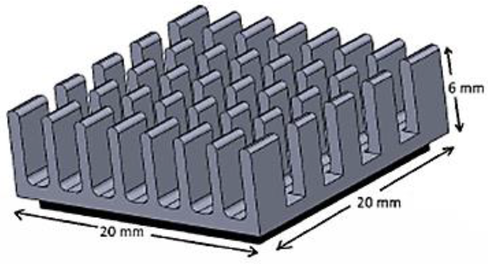
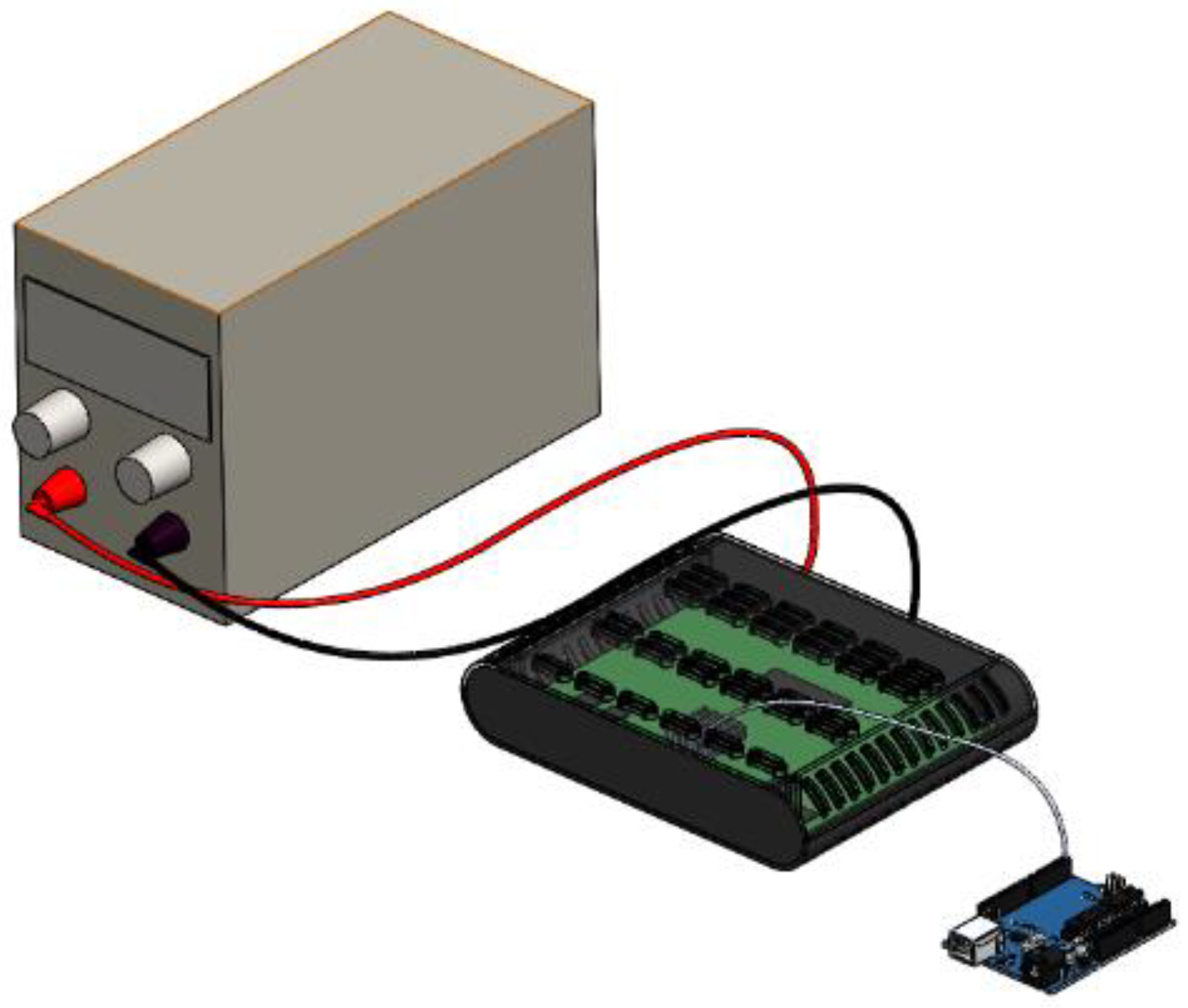
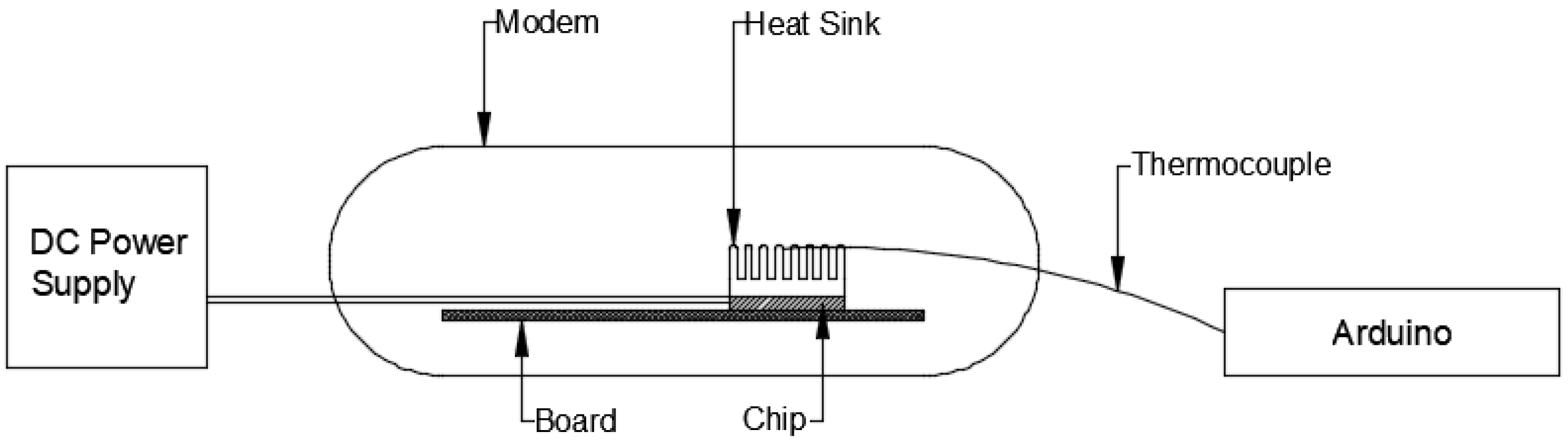
2.1. Apparatus and Instruments
2.2. Experimental Procedure
2.3. Uncertainty Analysis
3. PCM Thermophysical Properties
3.1. Differential Scanning Calorimetric Study
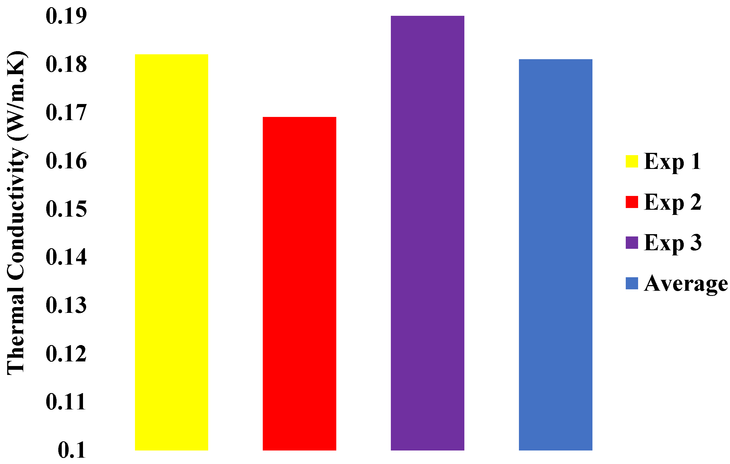
3.2. Thermal Conductivity Measurement
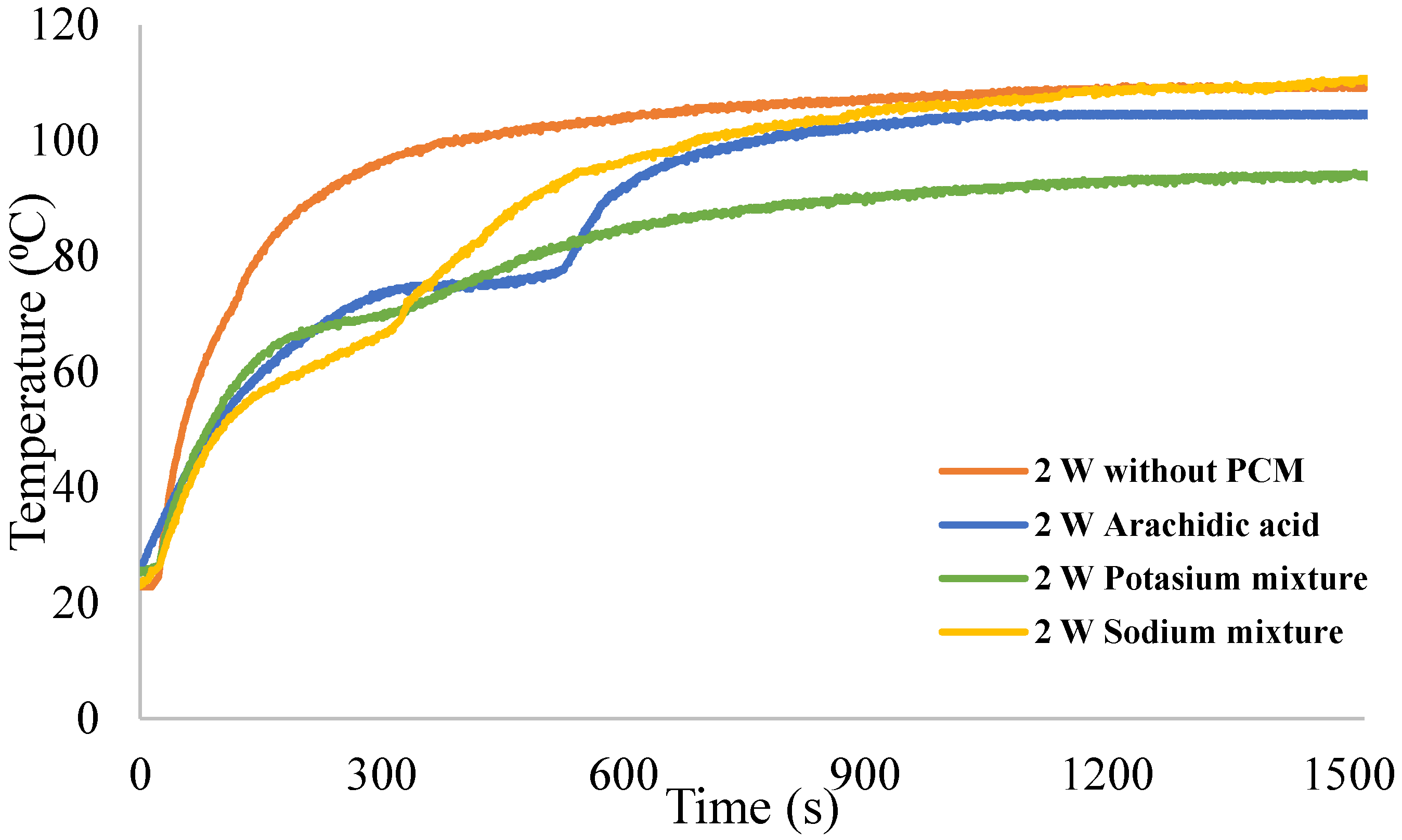
4. Results
5. Discussion
6. Conclusions
Author Contributions
Funding
Institutional Review Board Statement
Informed Consent Statement
Data Availability Statement
Conflicts of Interest
References
- Mihai, I. Heat transfer in minichannels and microchannels CPU cooling systems, chapter 4. In Heat Transfer—Theoretical Analysis, Experimental Investigations and Industrial Systems; Belmiloudi, A., Ed.; InTech: Rijeka, Croatia, 2011. [Google Scholar]
- Mjallal, I.; Farhat, H.; Hammoud, M.; Ali, S.; Assi, I. Improving the Cooling Efficiency of Heat Sinks through the Use of Different Types of Phase Change Materials. Technologies 2018, 6, 5. [Google Scholar] [CrossRef] [Green Version]
- Ellison, G.N. Thermal Computations for Electronics: Conductive, Radiative, and Convective Air Cooling; CRC Press: New York, NY, USA, 2011. [Google Scholar]
- Kuncoro, I.W.; Pambudi, N.A.; Biddinika, M.K.; Widiastuti, I.; Hijriawan, M.; Wibowo, K.M. Immersion cooling as the next technology for data center cooling: A review. J. Phys. Conf. Ser. 2019, 1402, 044057. [Google Scholar] [CrossRef]
- Tang, H.; Tang, Y.; Wan, Z. Review of applications and developments of ultra-thin micro heat pipes for electronic cooling. Appl. Energy 2018, 223, 383–400. [Google Scholar] [CrossRef]
- Watson, J.; Castro, G. High-temperature electronics pose design and reliability challenges. Analog Dialogue 2012, 46, 3–9. [Google Scholar]
- Isa, M.H.M.; Zhao, X.; Yoshino, H. Preliminary study of passive cooling strategy using a combination of PCM and copper foam to increase thermal heat storage in building facade. Sustainability 2010, 2, 2365–2381. [Google Scholar] [CrossRef] [Green Version]
- Thirugnanam, C.; Karthikeyan, S.; Kalaimurugan, K. Study of phase change materials and its application in solar cooker. Mater. Today Proc. 2020, 33, 2890–2896. [Google Scholar] [CrossRef]
- Shaito, A.; Hammoud, M.; Kawtharani, F.; Kawtharani, A.; Reda, H. Power enhancement of a photovoltaic module using different types of phase change materials. Energies 2021, 14, 5195. [Google Scholar] [CrossRef]
- Kawtharani, F.; Kawtharani, A.; Hammoud, M.; Hallal, A.; Shaito, A.; Assi, A.; Assi, I. Cooling PV modules using phase change material. In Proceedings of the 29th International Conference on Microelectronics, Beirut, Lebanon, 10–13 December 2017; pp. 347–351. [Google Scholar]
- Barzin, R.; Chen, J.J.; Young, B.R.; Farid, M.M. Application of PCM underfloor heating in combination with PCM wallboards for space heating using price-based control system. Appl. Energy 2015, 148, 39–48. [Google Scholar] [CrossRef]
- Shukla, A.; Buddhi, D.; Sawhney, R.L. Solar water heaters with phase change material thermal energy storage medium: A review. Renew. Sust. Energy Rev. 2009, 13, 2119–2125. [Google Scholar] [CrossRef]
- Joshy, N.; Hajiyan, M.; Siddique, A.; Tasnim, S.; Simha, H. Experimental investigation of the effect of vibration on phase change material (PCM) based battery thermal management system. J. Power Sources 2020, 450, 227717. [Google Scholar] [CrossRef]
- Assi, I.; Mjallal, I.; Farhat, H.; Hammoud, M.; Ali, S.; Shaer, A.A.L.; Assi, A. Using phase change material in heat sinks to cool electronics devices with intermittent usage. In Proceedings of the IEEE 7th International Conference on Power and Energy Systems ICPES, Toronto, ON, Canada, 1–3 November 2017; pp. 66–69. [Google Scholar]
- Mjallal, I.; Farhat, H.; Hammoud, M.; Ali, S.; Shaer, A.A.L.; Assi, A. Cooling Performance of Heat Sinks Used in Electronic Devices. In MATEC Web of Conferences; EDP Sciences: Ulis, France, 2018; Volume 171, p. 02003. [Google Scholar]
- Yang, G.; Yim, Y.J.; Lee, J.W.; Heo, Y.J.; Park, S.J. Carbon-Filled Organic Phase-Change Materials for Thermal Energy Storage: A Review. Molecules 2019, 24, 2055. [Google Scholar] [CrossRef] [PubMed] [Green Version]
- Fu, J.; Pourbakhsh, S.A.; Chen, X.; Li, M.; Lin, Z.; Hou, L.; Haring, F.; Gong, N.; Wang, J. On-chip thermal management method based on phase change material. In Proceedings of the 2017 IEEE 60th International Midwest Symposium on Circuits and Systems (MWSCAS), Medford, MA, USA, 6–9 August 2017; pp. 985–988. [Google Scholar]
- Ali, H.M.; Arshad, A.; Jabbal, M.; Verdin, P.G. Thermal management of electronics devices with PCMs filled pin-fin heat sinks: A comparison. Int. J. Heat. Mass Transf. 2018, 117, 1199–1204. [Google Scholar] [CrossRef] [Green Version]
- Hasan, M.I.; Tbena, H.L. Using of phase change materials to enhance the thermal performance of micro channel heat sink. Eng. Sci. Technol. Int. J. 2018, 21, 517–526. [Google Scholar] [CrossRef]
- Kandasamy, R.; Wang, X.Q.; Mujumdar, A.S. Transient cooling of electronics using phase change material (PCM)-based heat sinks. Appl. Therm. Eng. 2008, 28, 1047–1057. [Google Scholar] [CrossRef]
- Tan, F.L.; Tso, C.P. Cooling of mobile electronic devices using phase change materials. Appl. Therm. Eng. 2004, 24, 159–169. [Google Scholar] [CrossRef]
- Benli, H.; Durmuş, A. Performance analysis of a latent heat storage system with phase change material for new designed solar collectors in greenhouse heating. Sol. Energy 2009, 83, 2109–2119. [Google Scholar] [CrossRef]
- Coskun, A.K.; Atienza, D.; Rosing, T.S.; Brunschwiler, T.; Michel, B. Energy-efficient variable-flow liquid cooling in 3D stacked architectures. In Proceedings of the 2010 Design, Automation & Test in Europe Conference & Exhibition (DATE 2010), Dresden, Germany, 8–12 March 2010; pp. 111–116. [Google Scholar]
- Xie, H.; Ali, A.; Bhatia, R. The use of heat pipes in personal computers. In Proceedings of the Sixth Intersociety Conference on Thermal and Thermomechanical Phenomena in Electronic Systems (ITherm’98), Seattle, WA, USA, 27–30 May 1998; pp. 442–448. [Google Scholar]
- Mjallal, I.; Feghali, E.; Hammoud, M.; Habchi, C.; Lemenand, T. Exploring the colligative properties of Arachidic acid for potential use as PCM. Sol. Energy 2021, 214, 19–25. [Google Scholar] [CrossRef]
- Mjallal, I.; Hammoud, M.; Habchi, C.; Lemenand, T. Cost Effective Device to Characterize Phase Change Materials. Meas. Sci. Technol. 2020, 31, 025903. [Google Scholar] [CrossRef]


| Equipment | Experimental Error |
|---|---|
| Thermocouple | ±0.5 °C |
| Power supply | ±1% |
| Heater temperature stability | ±0.1 °C |
| Materials | Latent Heat (J/kg) | Specific Heat for Solid Phase (kJ/kg K) | Specific Heat for Liquid Phase (kJ/kg K) | Solidus Temperature (°C) | Liquidus Temperature (°C) |
|---|---|---|---|---|---|
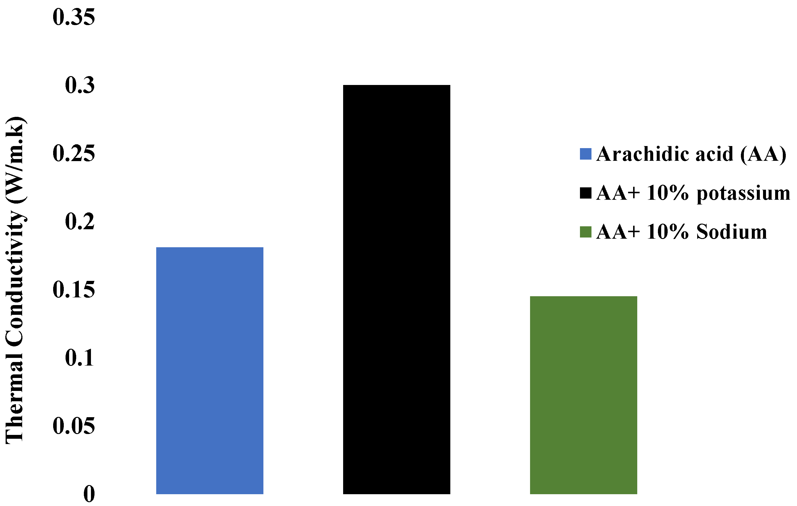
| Arachidic acid (AA) | 257.4 | 1.90 | 2.19 | 73.3 | 80.1 |
| AA + 10% potassium oleate | 214.0 | 1.90 | 2.36 | 50.0 | 83.3 |
| AA + 10% sodium decanoate | 222.1 | 2.33 | 2.30 | 48.0 | 82.7 |
| Peak Temperature (°C) | Time to Steady State (s) | |
|---|---|---|
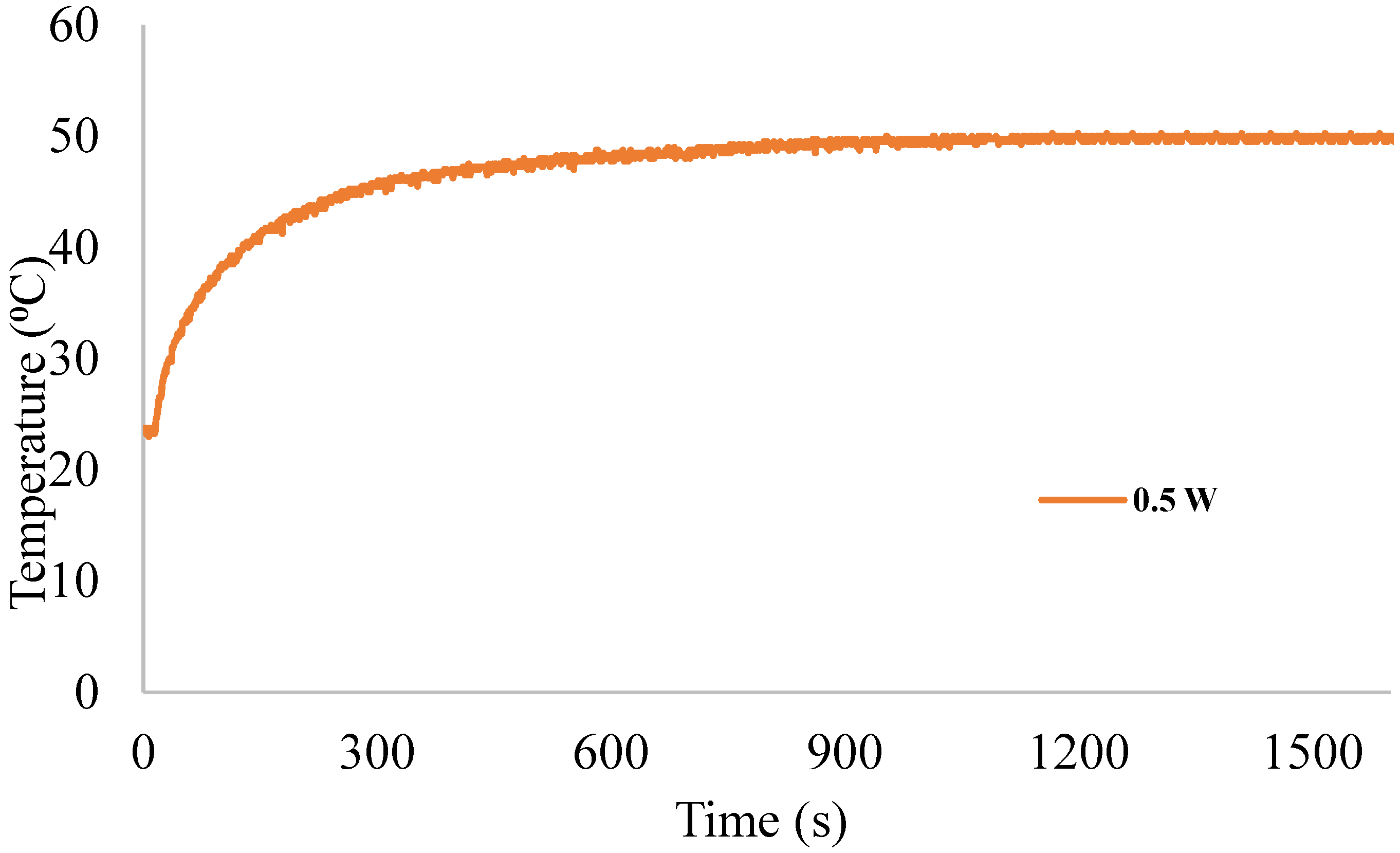
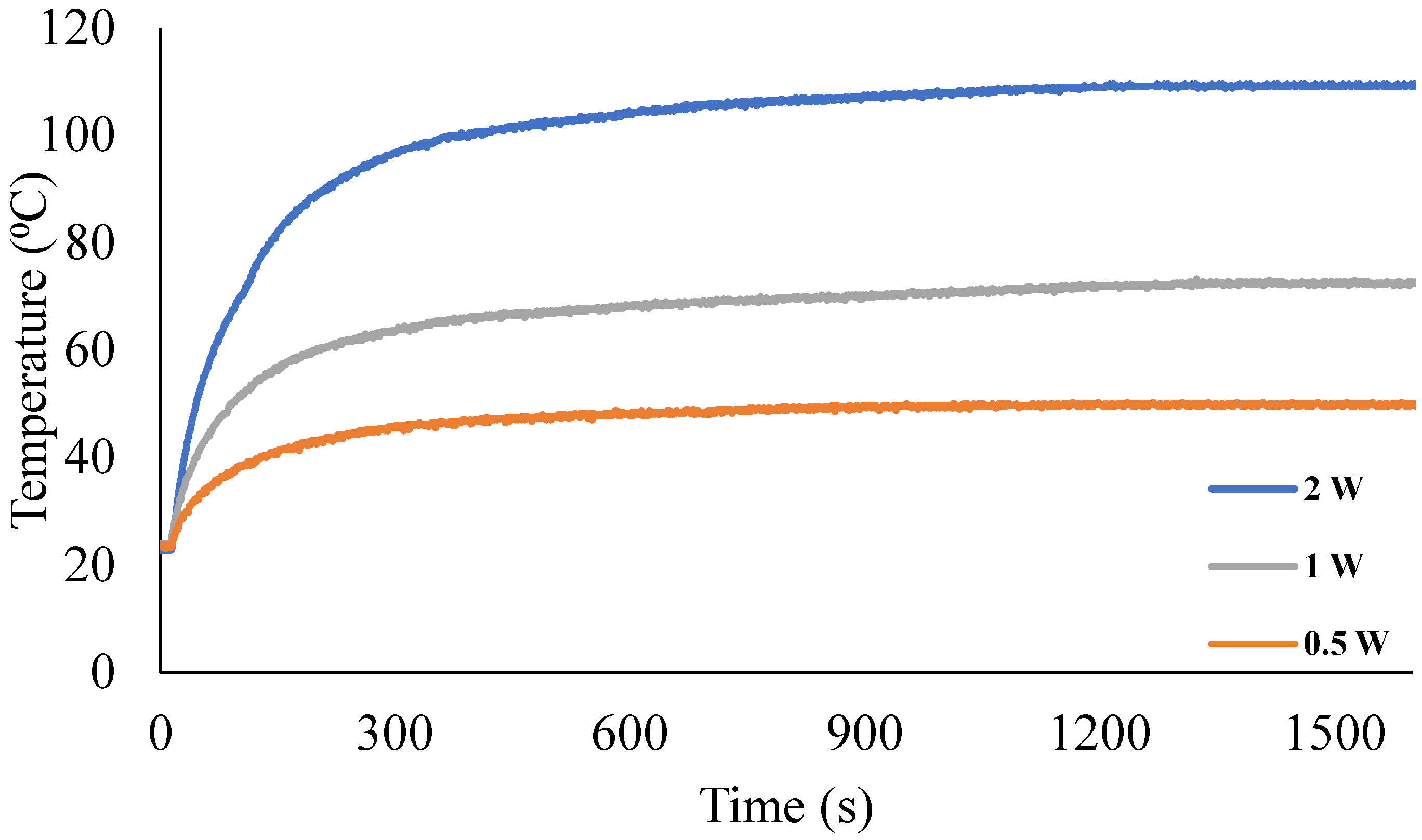
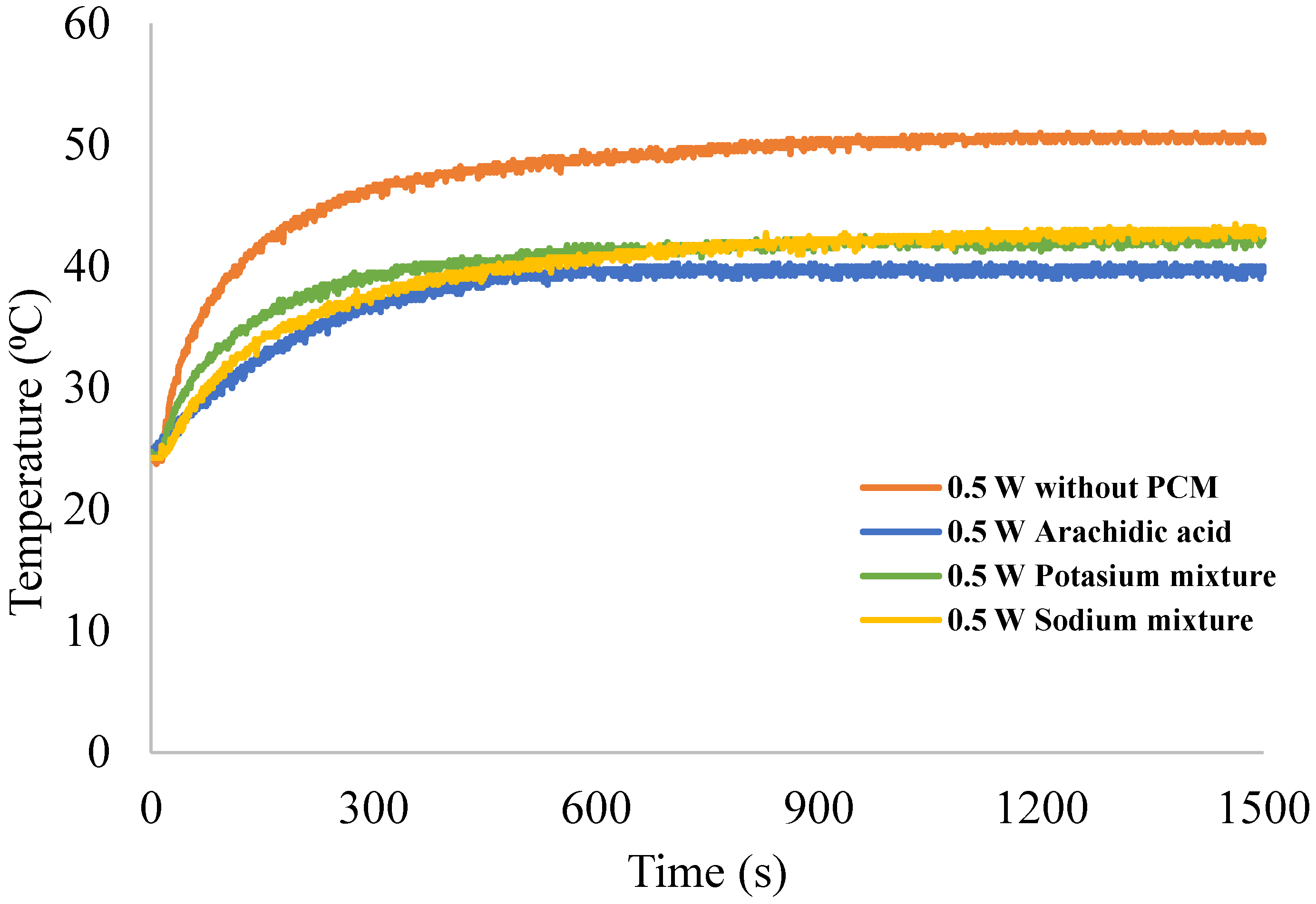
| 0.5 W | 50 | 900 |
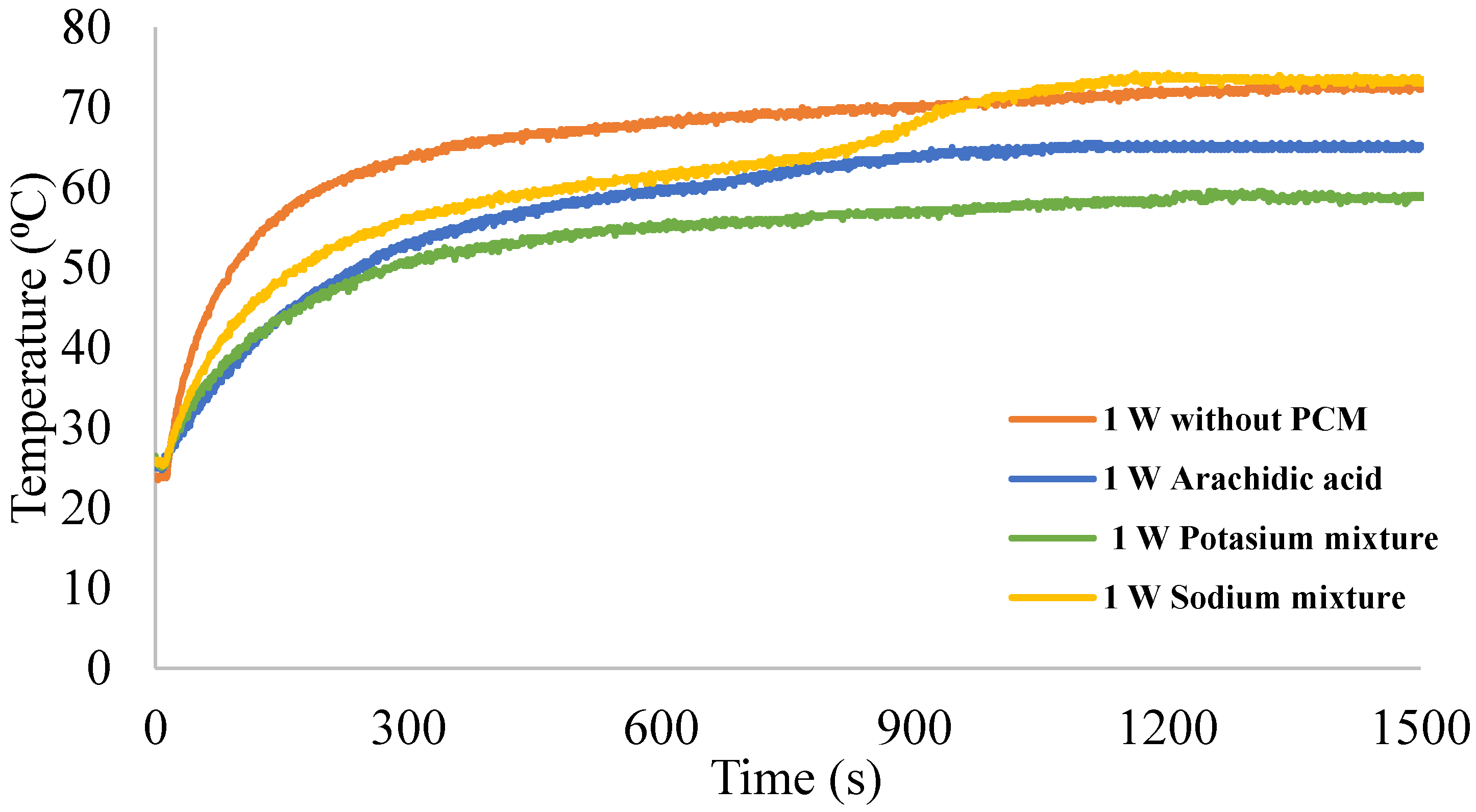
| 1 W | 72 | 850 |
| 2 W | 109 | 800 |
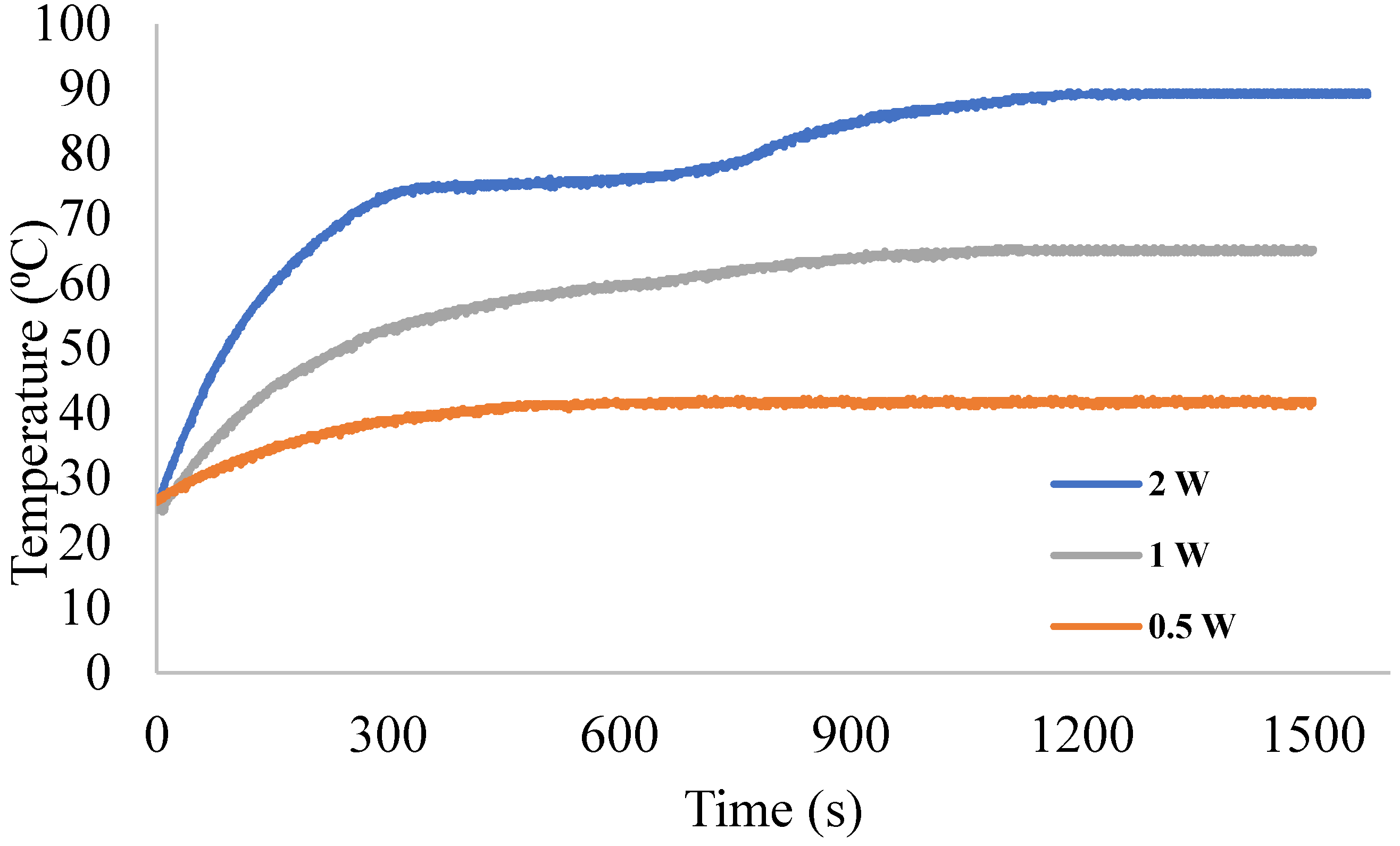
| 0.5 W (AA) | 41.5 | 473 |
| 1 W (AA) | 65 | 1120 |
| 2 W (AA) | 89 | 1100 |
| 0.5 W (AA + Potassium) | 42.5 | 500 |
| 1 W (AA + Potassium) | 58.5 | 560 |
| 2 W (AA + Potassium) | 95.25 | 1500 |
| 0.5 W (AA + Sodium) | 42 | 908 |
| 1 W (AA + Sodium) | 73 | 1160 |
| 2 W (AA + Sodium) | 104 | 1607 |
Publisher’s Note: MDPI stays neutral with regard to jurisdictional claims in published maps and institutional affiliations. |
© 2021 by the authors. Licensee MDPI, Basel, Switzerland. This article is an open access article distributed under the terms and conditions of the Creative Commons Attribution (CC BY) license (https://creativecommons.org/licenses/by/4.0/).
Share and Cite
Hammoud, M.; Mjallal, I.; Farhat, H.; Abdallah, N.; Habchi, C.; Lemenand, T. The Effect of Arachidic Acid Mixtures on the Cooling Performance of a Heat Sink. Appl. Sci. 2021, 11, 9201. https://doi.org/10.3390/app11199201
Hammoud M, Mjallal I, Farhat H, Abdallah N, Habchi C, Lemenand T. The Effect of Arachidic Acid Mixtures on the Cooling Performance of a Heat Sink. Applied Sciences. 2021; 11(19):9201. https://doi.org/10.3390/app11199201
Chicago/Turabian StyleHammoud, Mohammad, Ibrahim Mjallal, Hussien Farhat, Nour Abdallah, Charbel Habchi, and Thierry Lemenand. 2021. "The Effect of Arachidic Acid Mixtures on the Cooling Performance of a Heat Sink" Applied Sciences 11, no. 19: 9201. https://doi.org/10.3390/app11199201
APA StyleHammoud, M., Mjallal, I., Farhat, H., Abdallah, N., Habchi, C., & Lemenand, T. (2021). The Effect of Arachidic Acid Mixtures on the Cooling Performance of a Heat Sink. Applied Sciences, 11(19), 9201. https://doi.org/10.3390/app11199201