Abstract
A series of full-scale pushed out tests were performed on the Perfobond rib shear connector. The tests were designed to examine the performance of the Perfobond rib shear connector under different rib hole sizes and shapes, reinforcing bar sizes, rib thicknesses, as well as the presence of lateral forces. It has been revealed from the test results that the rib hole size and reinforcement diameter may not act independently, and the influence of one’s size is actually dependent on the size of the other one. The lateral forces also affect the performance of the shear connector; for example, the capacity of the shear connector would be larger under compression than under tension. The existence of transverse pretension stress accelerated the cracking of concrete, leading to the strength and stiffness of concrete, perforated plate, and reinforcing rebars unable to fully exert their effect. In addition, the constraint effect of transverse stress improved the strength and stiffness of concrete and delayed the concrete cracking, bringing the strength and stiffness of concrete, perforated plate, and reinforcing rebars into full play, and resulting in a significant improvement in the shear capacity of Perfobond rib shear connectors.
1. Introduction
Steel–concrete composite girders are widely used because of their superior durability and accelerated construction time. The design and analysis of the composite girders are closely dependent on the composite action through the steel and concrete components. Therefore, the capacity and behavior of the shear connection become essential in composite girders. In the composite girder, slip between the concrete top and steel girder is almost unavoidable. However, repeated and excessive slip must be prevented, as it may not only cause the fatigue at the end of the shear connector itself, but also tear up the concrete around the shear connector and lead to connection issues.
The Perfobond rib (Perfobond Leiste in German [1]) shear connector represents a type of shear connector that is perforated and reinforced with steel bars to utilize the dowel action to provide more reliable shear resistance than the traditional stud shear connectors in composite construction. The Perfobond rib shear connector was introduced in 1987 by a German consulting firm as the result of the construction of the 3rd Caroni River Bridge in Venezuela [1]. The Caroni River Bridge was designed to take a heavy live load and that live load over time may result in connection fatigue issues if traditional shear studs were to be used. However, the Perfobond rib shear connector serves as an option because it has advantages over the traditional shear studs of very minimal slip under service condition and being able to maintain the connection between the slip and the live load under the associated fatigue threshold.
For steel–concrete composite beam bridges, the distribution length of the shear connectors at the steel–concrete connection is relatively large, and the end resistance of the concrete is relatively small, which can be ignored. The main feature of the steel–concrete composite beam bridge is that transverse prestressed steel bars are set in the concrete deck. The pre-compression stress of the transverse prestressed steel bars will cause the concrete around the shear connectors to be under compressive stress. The confinement restraint will increase the friction between the steel plate and the concrete, so it is necessary to consider the influence of the confinement restraint caused by the transverse prestress on the bearing capacity of the shear connector. In addition, under the working load of the composite beam bridge, the concrete around the shear connectors may be under tensile stress. This article comprehensively considers the mechanical characteristics of the steel–concrete composite beam bridge, and analyzes the bearing capacity and the mechanical mechanism of the shear connector considering the transverse prestressed effect.
2. Literature Review
There have been abundant studies on Perfobond rib shear connectors. The key question to answer is what configurations of the perforated holes and steel reinforcement bars would provide the optimum capacity and ductility. The superior and reliable bond of Perfobond rib shear connectors distinguishes them from other types of connectors, and there are a number of sources from which bond comes. Namely, the concrete and reinforcement mechanical dowel action, the cohesive and frictional bond at the concrete and steel rib interface, and the concrete at the end of the connector as bearing. The mechanical dowel action bond is unique to the Perfobond rib shear connector and significantly increases connector’s ductility. It has been studied through the comparison between specimens with and without rib holes and lateral reinforcement [2,3,4,5,6,7,8,9,10,11,12,13,14,15,16,17,18,19,20,21,22,23]. The cohesive bond and end concrete bearing effect are not unique to the Perfobond rib shear connector, and are characteristics shared by most shear connectors. However, for the continuous or very dense Perfobond rib arrangement, the end bearing concrete may well be negligible owing to the limited amount of concrete between connectors as bearing [4].
The behavior of the Perfobond rib shear connectors is primarily studied through the push-out tests. Su et al. focused on the mechanical dowel effect of various sizes of holes and reinforcement by eliminating the concrete bearing effect and the cohesive and frictional bond through foam layers [4]. Ahn et al. studied the influences of concrete strength, rib spacing of double rib specimens, concrete bearing, and lateral reinforcement, and reported a significant increase in strength due to lateral reinforcement in addition to the conclusions that the specimen fails primarily because of the concrete instead of the steel rib, and the strength and ductility of the specimens are more associated with the concrete strength [12]. In Ahn’s tests, a cohesive and frictional bond is also eliminated by adding grease at the concrete steel interface. Vianna et al. studied the influence of the perforated rib holes and the lateral reinforcement, and reported that, for 120 mm specimens, the existence of rib holes and lateral reinforcement would noticeably increase the Perfobond rib shear connector’s strength as well as the ductility, but, as for the thicker 200 mm specimens, the influence may be limited to only a few percentages because of the closely spaced rib holes [20]. Vianna et al. in another study compared conventional Perfobond shear connectors with new T-Perfobond shear connectors and reported a significant improvement in capacity in T-Perfobond shear connectors over conventional ones [18]. Kim et al. studied a new Y-Perfobond rib shear connector of different configurations and compared it with the conventional Perfobond rib shear connector, and finally concluded that the Y-Perfobond rib shear connector has better performance than the conventional Perfobond rib shear connector [3]. Costa-Neves et al. experimentally compared T-Perfobond, I-Perfobond, 2T-perfobond, and conventional Perfobond rib shear connectors and reported a significant improvement in the performance of those new types of connectors [9]. Zheng et al. conducted tests and carried out a nonlinear finite element analysis of Perfobond shear connectors with different shapes and sizes of holes, and found out that the hole shape and direction have a negligible difference in the push-out tests [2]. Rodrigues et al. compared various Perfobond shear connectors at both room and elevated temperatures and observed a reduced capacity at higher temperatures [7]. Valente et al. (2004) studied the Perfobond shear connector on lightweight concrete [8] and, like in Ahn’s and Zheng’s tests of conventional concrete [2,12], also reported no damage to the shear connector at failure. Finite element modeling as an approach of investigation has also been reported; for example, Oguejio et al. and Nguyen et al. studied the performance of a shear connector using the finite element approach [5,19]. On the other hand, composite girders built with Perfobond shear connectors have been tested. Andrade et al. and Vellasco et al. tested composite bridges [15,16]. He et al. used ultra-high-performance concrete (UHPC) and found that mixing a 2% volume fraction of steel fibers in UHPC could increase the average bond strength at the plate–concrete interface and shear resistance of the concrete dowels by 82% and 50%, respectively [21]. Zhang et al. developed an analytical model based on the load–slip characteristics of a single shear connector and load–deformation compatibility of a perforated steel plate and concrete component. The model was validated through full-scale experiments [22]. Wang et al. analyzed the effect of concrete stress state; it was found that the shear capacity of the connectors increased when a transverse compressive stress was present, but it decreased when a transverse tensile stress was present. Using the results from these tests, a design equation that takes all of these factors into consideration in determining the shear capacity of Perfobond shear connectors is proposed [23].
While many previous studies focused on the existence of rib holes and lateral reinforcement, this study makes efforts to determine the influence of the sizes of rib holes, lateral reinforcement, and thickness of steel plate, as well as the influence of lateral forces. This study aims to shed some light on this topic through a series of full-scale pushed out tests of the Perfobond shear connectors.
3. Test Apparatus and Procedures
3.1. Test Apparatus and Specimen Details
The push-out tests are divided into 13 groups and each group consists of either two or three identical specimens, as in Table 1. There are three types of specimens, namely, BH-UN, BH-PT, and BH-PP. BH-UN specimens are tested to study the influence of the effects of rib holes, transverse reinforcement bars, and rib thickness. Thus, there are no external transverse forces on those BH-UN specimens. BH-PT and BH-PP specimens are designed to study the influence of transverse tensile and compressive forces, respectively. Thus, hydraulic jacks are placed within BH-PT specimens and post-tensioned prestressing tendons are placed within BH-PP specimens to examine the influences of transverse tensile and compressive forces. Detailed properties and dimensions of those three types of specimens are provided in Table 1, Figure 1, Figure 2 and Figure 3. All the specimens have three rib holes and three transverse reinforcement bars on each side. Those test specimens are all designed to exclude the influence of the concrete components under the shear connection by leaving a gap under the rib plate, as shown in Figure 1, Figure 2 and Figure 3. The concrete strength of all the specimens is 55 MPa. The reinforcement is HRB 400 and the rib plate is Q345qE.

Table 1.
Specimen dimensions and transverse forces.
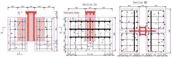
Figure 1.
Dimensions of push-out specimens and perforated rib: BH-UN (unit: mm).
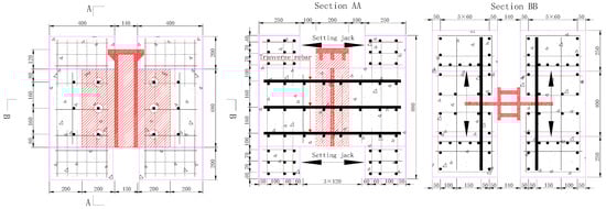
Figure 2.
Dimensions of push-out specimens and perforated rib: BH-PT (unit: mm).
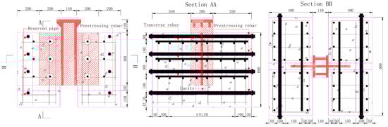
Figure 3.
Dimensions of push-out specimens and perforated rib: BH-PP (unit: mm).
In addition, as the concrete at the bottom of the steel rib could affect the resistance of the shear connection, a gap was left under the steel rib in the BH-UN and BH-PP specimens, as shown in Figure 1 and Figure 3. BH-PT specimens already had space for the transverse force, so the gap is not necessary, as in Figure 2.
3.2. Test Procedures
During the tests, the each specimen was tested in two stages. The first stage test intends to test their behavior within the elastic limit and the second stage test then evaluates their ultimate strength. The yielding load was first determined through finite element analysis, but as tests began, the yielding load was adjusted according to the previous test specimen results.
During each first stage test, specimens were loaded with an increment of 0.2 times the calculated yielding load each time from zero to its yielding and the load was held for 5 min at each load level. The second stage test then used the load increment of 0.1 times the calculated yielding load and the load was also held for five minutes at each load level until failure occurred.
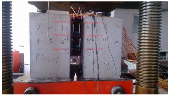
Figure 4.
Test apparatus.
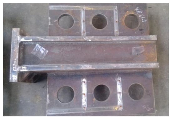
Figure 5.
Steel structure.
4. Results Discussion
The influences of rib holes diameter, rib thickness, and lateral rebar diameter on the load–slip relationship are discussed. The push-out test results of specimens are reported in Table 2. Pu is the average value of the shear bearing capacity of the single-hole shear connector, which is obtained by dividing the total shear bearing capacity of the porous shear connector by the number of shear connectors; δu is the average value of the corresponding slip.
Table 2.
Push-out test results.
4.1. Rib Hole Diameter
The specimen groups BH-1 versus BH-3, BH-2 versus BH-4, and BH-5 versus BH-7 are discussed. BH-1 and BH-3 specimens both have the same reinforcement of 16 mm diameter and 20 mm thick steel plates, and the only difference is that BH-1 specimens have 60 mm diameter holes in the rib and BH-3 specimens have 75 mm diameter holes in the rib. Therefore, these two specimens are compared in Figure 6.
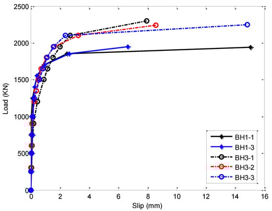
Figure 6.
Load–slip relationship.
As demonstrated in Figure 6, BH-3 specimens obviously have better ultimate resistance. While the specimen properties and the reinforcement steel bars are the same, the larger rib hole diameter in BH-3 specimen provides better shear resistance (about 20% improvement) by means of more concrete dowel action. The tested specimens were broken up and structural components were analyzed immediately after the tests to examine the deformation and failure modes, as demonstrated in Figure 7 and Figure 8.
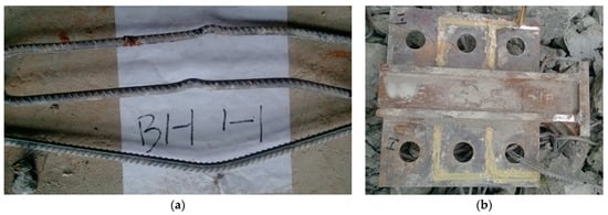
Figure 7.
Rib plate and reinforcement of the BH 1-1 specimen after the test: (a) Deformation form of reinforcement; (b) Deformation form of rib plate.
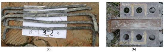
Figure 8.
Rib plate and reinforcement of the BH 3-2 specimen after the test: (a) Deformation form of reinforcement; (b) Deformation form of rib plate.
In Figure 7 and Figure 8, the BH 1-1 specimen had a reinforcement failure, whereas the BH 3-2 specimen had a concrete dowel failure. Therefore, the reinforcement bars in the BH 1-1 specimen had more deformation than the same reinforcement bars in the BH 3-2 specimen. This is because the smaller rib holes trapped a smaller amount of concrete to provide shear resistance and, consequently, the reinforcement bars have to deform more to provide shear resistance. On the other hand, if the openings in the steel ribs are large enough, like in the BH 3-2 specimen, the concrete dowel will provide the majority of the shear resistance and the concrete inside of the steel rib will fail before the reinforcement bars fail.
Similarly to BH-1 and BH-3 specimens, BH-2 and BH-4 specimens both have the same reinforcement diameter of 20 mm and thickness of 20 mm, but BH-2 specimens have 60 mm diameter rib holes, whereas BH-4 specimens have 75 mm diameter rib holes. The bond–slip relationships of these two specimens are plotted in Figure 9.
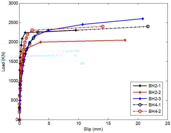
Figure 9.
Load–slip relationship.
Different from BH-1 and BH-3 specimens, BH-2 and BH-4 specimens almost have the same bond–slip relationship and resistance. This can be explained by considering the difference that BH-1 and BH-3 specimens have 16 mm diameter reinforcement bars, whereas BH-2 and BH-4 specimens have 20 mm diameter reinforcement bars. The larger diameter reinforcement bars would provide adequate shear resistance, such that the increase in the amount of concrete dowel action from the larger rib hole specimens will not play such an important role any more. More detailed analysis is made possible by examining the failure modes of the reinforcement bars, concrete dowel, and rib plates in Figure 10, Figure 11 and Figure 12.
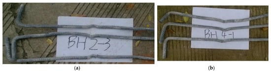
Figure 10.
Rib plate and reinforcement of BH 2-3 and BH 4-1 specimens after the test: (a) Deformation form of reinforcement of BH 2-3; (b) Deformation form of reinforcement of BH 4-1.
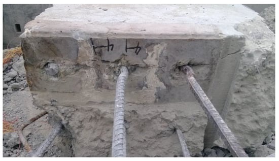
Figure 11.
Concrete dowel and reinforcement of the BH 4-1 specimen after the test.
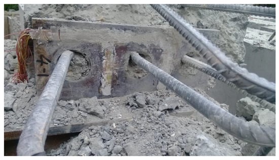
Figure 12.
Concrete dowel, rib plate, and reinforcement of the BH 4-1 specimen after the test.
As demonstrated in Figure 10, unlike in the BH 3-2 specimen, both BH 2-3 and BH 4-1 specimens had reinforcement bars failures, and those reinforcement bars deformed heavily. The heavily deformed reinforcement bars indicate that a large amount of the shear loads were shared by the reinforcement bars, and the concrete in Figure 11 and Figure 12 also confirmed that the reinforcement bars take the majority of the shear loads.
Another comparison ground is made in Figure 13. BH-5 and BH-10 specimens have identical reinforcement diameters of 25 mm and rib thickness of 20 mm, and the only difference between them is that the BH-5 specimen has a rib hole diameter of 75 mm, whereas the BH-10 specimens has a rib hole diameter of 90 mm.
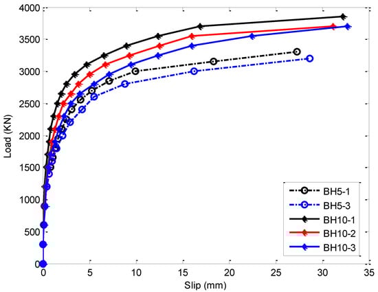
Figure 13.
Load–slip relationship.
As demonstrated in Figure 13, the BH-10 specimen has better overall resistance (11% improvement) and ductility (55% improvement) than the BH-5 specimen. The failure modes of those specimens are analyzed in Figure 14 and Figure 15.
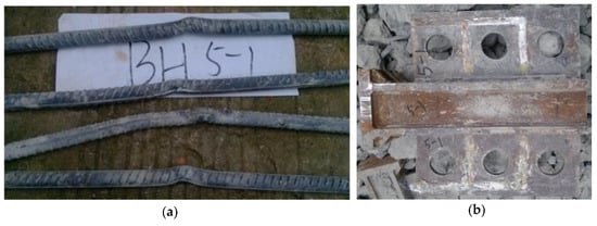
Figure 14.
Rib plate and reinforcement of the BH 5-1 specimen after the test: (a) Deformation form of reinforcement; (b) Deformation form of rib plate.
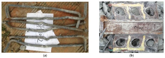
Figure 15.
Rib plate and reinforcement of the BH 10-2 specimen after the test: (a) Deformation form of reinforcement; (b) Deformation form of rib plate.
A couple of things are noticed in Figure 14 and Figure 15. Firstly, the BH-10 specimen has more noticeable deformation in both reinforcement bars and the ribs than the BH-5 specimen. Secondly, the rib in the BH-10 specimen is very heavily deformed, whereas the rib in the BH-5 specimen is not. This is because the increased rib hole diameter in the BH-10 specimen on one hand enhances the concrete dowel action, but on the other hand decreases the strength of the rib itself.
4.2. Lateral Reinforcement Diameter
The specimen groups BH-1s versus BH-2s, BH-3s versus BH-4s and BH-5s, and BH-7s versus BH-8s are discussed. The specimens’ dimensions can be found in Table 1.
As demonstrated in Figure 16 and Figure 17, the BH-2 specimen has slightly higher resistance than the BH-1 specimen, but BH-3 and BH-4 specimens have almost the same resistance. As analyzed previously for the rib hole diameter, concrete in the rib holes and reinforcement all contribute to the overall resistance of the shear connector. However, their contribution would be much more prominent in specimens with smaller sizes of the other factor. For example, for the comparison in Figure 16 and Figure 17, BH-1 and BH-2 specimens have 60 mm diameter rib holes and the same increment in the reinforcement diameter would bump up the resistance more obviously than in BH-3 and BH-4 specimens, which have 75 mm diameter rib holes.
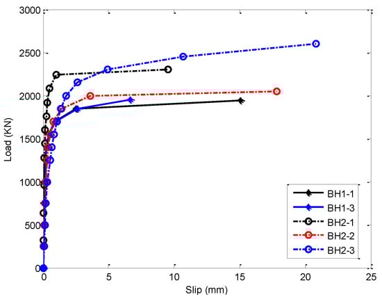
Figure 16.
Load–slip relationship.
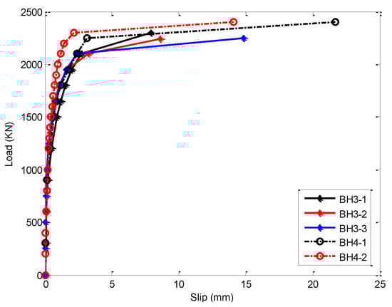
Figure 17.
Load–slip relationship.
The failures modes of BH-1 and BH-2 specimens in Figure 7 and Figure 10 as well as Table 1 demonstrate and confirm the dominant roles of the reinforcement bars.
Similarly to what has been discussed in the comparison between Figure 16 and Figure 17, Figure 18 also shows that the increase in reinforcement diameter from 25 mm to 28 mm results in little changes in the BH-10 and BH-11 specimens, which have the largest rib hole diameter of 90 mm. This is because, for BH-10 and BH-11 specimens, the rib plates failed before the concrete and reinforcement inside the rib holes failed because of the largest rib holes, which increase the concrete dowel action resistance and decrease the shear resistance of the rib plates, and the reinforcement bars were actually not at their maximum capacity when the rib plates failed. On the other hand, when the rib plates have much more shear resistance than reinforcement steel bars and concrete dowel actions, the specimens with larger diameter reinforcement bars would have more shear resistance and ductility than those with smaller diameter reinforcement bars, as shown in Figure 19. In Figure 19, BH-4 and BH-5 specimens both have 75 mm diameter rib holes, but the BH-4 specimen has 20 mm diameter reinforcement bars and the BH-5 specimen has 25 mm reinforcement bars, as shown in Table 1.
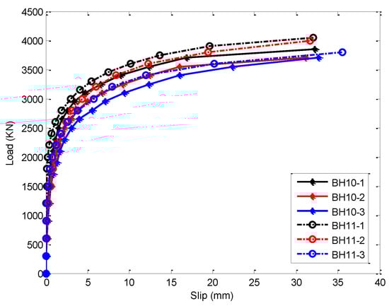
Figure 18.
Load–slip relationship.
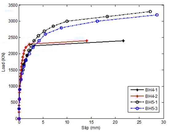
Figure 19.
Load–slip relationship.
From Figure 15 and Figure 20, BH-10 and BH-11 specimens both show apparent rib plates shear failures, whereas all other specimens show little shear deformation of the rib plates. BH-4 and BH-5 specimens, as in Figure 10, Figure 11 and Figure 12, and Figure 14, show apparent reinforcement bars failures, which confirms the dominant roles of reinforcement bars in the specimens’ failures.
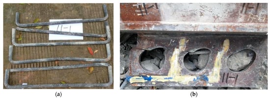
Figure 20.
Rib plate failures of the BH-11 specimen after test: (a) Deformation form of reinforcement; (b) Deformation form of rib plate.
BH-5 and BH-9 specimens are compared and the influence of rib thickness is discussed. The BH-5 specimen has a 20 mm thick rib plate, whereas the BH-9 specimen has a 24 mm thick rib plate. All other dimensions and properties are the same for the two specimen groups.
As demonstrated in Figure 21, with all other factors being the same, a thicker rib would definitely increase the resistance (22% improvement). This is because the thicker rib increases the amount of concrete inside the rib holes, and that concrete will increase the resistance of the shear connection. The increased amount of concrete in the thicker rib holes would also reduce the shear stress of the transverse reinforcement and concrete, because the same amount of shear force will be applied to a wider edge.
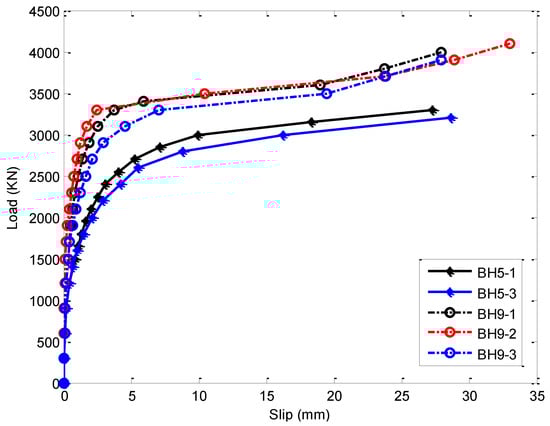
Figure 21.
Load–slip relationship.
4.3. Transverse Forces
The transverse forces are applied to specimens to examine their influences on the behavior in the push-out test. There are two kinds of transverse forces that are applied to the specimens: compressive and tensile forces. The tensile forces were applied by means of hydraulic jacks and the compressive forces were applied by post-tensioning prestressed steel bars, as in Figure 2 and Figure 3.
4.3.1. Transverse Tensile Force
As shown in Figure 22, the transverse tensile forces are very influential on the load–slip relationship of the shear connectors. BH6P, BH6A, and BH6 (1 and 2) all have the same dimensions and properties. BH6P is the control specimen and no transverse pressure is applied. In BH6-1 and BH6-2, 2 MPa tensile stress is applied. In BH6A, 3 MPa tensile stress is applied. The specimens with higher tensile stresses applied on them have lower resistance (14% reduction of yielding load), but better ductility (260% improvement of slip). However, the difference between BH6A and BH6, which have 3 MPa and 2 MPa tensile stresses, respectively, is smaller than the difference between BH6P and BH6, which have 0 MPa and 2 MPa, respectively. Specifically, at 10 mm slip, BH6P has about 3100 KN of load, BH6A has about 2000 KN of load, and BH6 has about 2200 KN of load. Thus, at 10 mm slip, the difference in load between BH6A and BH6 is 200 KN, whereas the difference between BH6P and BH6 is 900 KN.
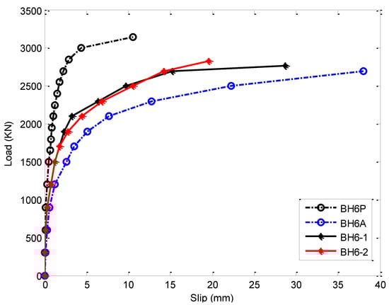
Figure 22.
Load–slip relationship.
As shown in Figure 23, the reinforcement bars and the rib plate are both in good condition with no obvious sign of yielding. This is because the tensile stress applied to those specimens makes the concrete in the rib holes more likely to yield before steel components.
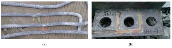
Figure 23.
Rib plate and reinforcement of the BH 6-1 specimen after the test: (a) Deformation form of reinforcement; (b) Deformation form of rib plate.
In Figure 24, BH-6P and BH-7s (1 and 2) both have the same properties and dimensions. The difference between those two groups is the amount of tensile stress. BH-6P is the control specimen and has no transverse tensile stress, whereas BH-7 has 1 MPa tensile stress. The difference in terms of the load–slip relationship is negligible. However, the BH7 specimen has a longer slip. For example, BH-6P’s failure slip is about 10 mm, whereas BH-7’s failure slip is about 22 mm. Apparently, the BH-7 specimen has better ductility than BH-6P.
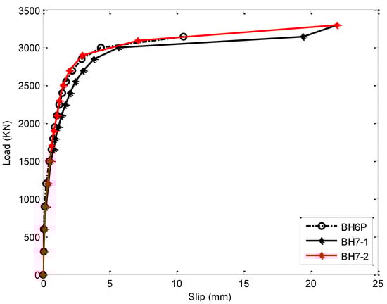
Figure 24.
Load–slip relationship.
4.3.2. Transverse Compressive Force
In Figure 25, BH-5 (1 and 3) and BH-8 specimens (1, 2, and 3) have the same properties and dimensions. However, BH-5 is the control specimen and does not have transverse forces applied, whereas BH-8 has 2 MPa compressive stress applied to the specimen. The load–slip relationships of all the tested BH-5 and BH-8 specimens have a very small difference; for example, the BH-8 specimens has better ductility (71% improvement in slip).
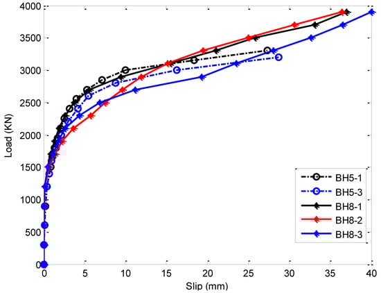
Figure 25.
Load–slip relationship.
5. Failure Modes of Shear Connections
The overall resistance of the Perfobond shear connector comes from three sources: the reinforcement bars, rib plate, and concrete in rib holes. As observed in the series of tests and Table 1, failures can be caused by any of those three possible factors. For example, BH-10 and BH-11 specimens fail because of the low shear strength of the rib plate, as shown in Figure 20. The BH-3 specimen fails because of weak concrete within the rib holes, as shown in Figure 26. Specimens fail because of failure of reinforcement bars, as shown in Figure 27.
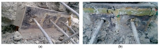
Figure 26.
Concrete dowel failures of the BH3 specimen after the test: (a) Concrete dowel failures of the BH3-1 specimen; (b) Concrete dowel failures of the BH3-2 specimen.
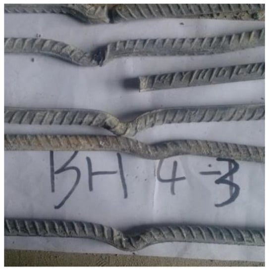
Figure 27.
Reinforcement bars failures of the BH4 specimen after the test.
6. Conclusions
This study carries full-scale tests on Perfobond rib shear connectors to study the influences of rib thickness, rib holes diameter, reinforcement bar diameter, and transverse forces on performance shear connectors’ performance. Upon analyzing the test data, conclusions are made as below:
- Rib hole diameter has an influence on the overall resistance of the shear connection. However, the influence depends on the diameter of the reinforcement bars. For example, when the rib hole diameter increases from 60 mm to 75 mm, the influence is obvious on the test specimens with 16 mm diameter reinforcement bars. However, the same amount of increase in rib hole diameter results in no obvious change in the bond–slip relationship on the specimens with 20 mm diameter reinforcement bars.
- A larger rib holes diameter, however, can increase the resistance of the shear connection and, on the other hand, also decreases the strength of the rib plate and causes failure of the shear connection, as in BH-10 and BH-11 specimens.
- The reinforcement bar diameter also has an influence on the resistance of the shear connection. However, the influence also depends on the rib holes. If the rib holes are large enough, the concrete dowel failure will dominate and the reinforcement bars would not contribute much to the overall shear resistance.
- A thicker rib thickness would increase the resistance of the shear connection; however, the increase in the resistance is not as efficient as other factors because the main source of shear resistance comes from the concrete and reinforcement dowel.
- The existence of transverse pretension stress accelerated the cracking of concrete, leading to the strength and stiffness of concrete, perforated plate, and reinforcing rebars being unable to exert their effect fully. As a result, the shear capacity of Perfobond shear connectors was reduced by about 10%. In addition, the constraint effect of transverse stress improved the strength and stiffness of concrete and delayed the concrete cracking, bringing the strength and stiffness of concrete, perforated plate, and reinforcing rebars into full play, and resulting in a significant improvement (20%) in the shear capacity of Perfobond shear connectors.
Author Contributions
Data curation, Q.H., Z.A., X.W. (Xingke Wen), Y.W. and Z.Z.; Writing—original draft, X.W. (Xuewei Wang); Writing—review & editing, Z.A. and G.L. All authors have read and agreed to the published version of the manuscript.
Funding
This research received no external funding.
Data Availability Statement
Data available in a publicly accessible repository.
Acknowledgments
The authors would like to thank Liang Du, Hongxue Li, and Lunliang Duan for the help during the tests and report preparation, and Yuzhi Zhang, Shengai Cui, and Suidi Song for the support and suggestions throughout this project.
Conflicts of Interest
The authors declare no conflict of interest.
References
- Zellner, W. Recent designs of composite bridges and a new type of shear connectors. In Composite Construction in Steel and Concrete; American Society of Civil Engineers: New York, NY, USA, 1987; pp. 240–252. [Google Scholar]
- Zheng, S.; Liu, Y.; Yoda, T.; Lin, W. Parametric study on shear capacity of circular-hole and long-hole perfobond shear connector. J. Constr. Steel Res. 2016, 117, 64–80. [Google Scholar] [CrossRef]
- Kim, S.H.; Choi, K.T.; Park, S.; Park, S.M.; Jung, C.Y. Experimental shear resistance evaluation of Y-type perfobond rib shear connector. J. Constr. Steel Res. 2013, 82, 1–18. [Google Scholar] [CrossRef]
- Su, Q.T.; Wang, W.; Luan, H.-W.; Yang, G.T. Experimental research on bearing mechanism of perfobond rib shear connectors. J. Constr. Steel Res. 2014, 95, 22–31. [Google Scholar] [CrossRef]
- Oguejiofor, E.C.; Hosain, M.U. Numerical analysis of push-out specimens with perfobond rib connectors. Comput. Struct. 1997, 62, 617–624. [Google Scholar] [CrossRef]
- Vianna, J.; Costa-Neves, L.; Vellasco, P.; de Andrade, S. Structural behaviour of T-Perfobond shear connectors in composite girders: An experimental approach. Eng. Struct. 2008, 30, 2381–2391. [Google Scholar] [CrossRef] [Green Version]
- Rodrigues, J.P.C.; Laím, L. Behaviour of Perfobond shear connectors at high temperatures. Eng. Struct. 2011, 33, 2744–2753. [Google Scholar] [CrossRef]
- Valente, I.B.; Cruz, P. Experimental analysis of Perfobond shear connection between steel and lightweight concrete. J. Constr. Steel Res. 2004, 60, 465–479. [Google Scholar] [CrossRef] [Green Version]
- Costa-Neves, L.; Figueiredo, J.; Vellasco, P.; Vianna, J.D.C. Perforated shear connectors on composite girders under monotonic loading: An experimental approach. Eng. Struct. 2013, 56, 721–737. [Google Scholar] [CrossRef]
- Cândido-Martins, J.P.; Costa-Neves, L.F.; Vellasco, P.D.S. Experimental evaluation of the structural response of Perfobond shear connectors. Eng. Struct. 2010, 32, 1976–1985. [Google Scholar] [CrossRef]
- Gattesco, N.; Giuriani, E. Experimental study on stud shear connectors subjected to cyclic loading. J. Constr. Steel Res. 1996, 38, 1–21. [Google Scholar] [CrossRef]
- Ahn, J.-H.; Lee, C.-G.; Won, J.-H.; Kim, S.-H. Shear resistance of the perfobond-rib shear connector depending on concrete strength and rib arrangement. J. Constr. Steel Res. 2010, 66, 1295–1307. [Google Scholar] [CrossRef]
- Oehlers, D.; Foley, L. The fatigue strength of stud shear connections in composite beams. Proc. Inst. Civ. Eng. 1985, 79, 349–364. [Google Scholar] [CrossRef]
- Lee, P.G.; Shim, C.S.; Chang, S.P. Static and fatigue behavior of large stud shear connectors for steel–concrete composite bridges. J. Constr. Steel Res. 2005, 61, 1270–1285. [Google Scholar] [CrossRef]
- Vellasco, P.D.S.; de Andrade, S.A.L.; Ferreira, L.T.S.; de Lima, L.R.O. Semi-rigid composite frames with perfobond and T-rib connectors Part 1: Full scale tests. J. Constr. Steel Res. 2007, 63, 263–279. [Google Scholar] [CrossRef]
- de Andrade, S.A.L.; Vellasco, P.D.S.; Ferreira, L.T.S.; Lima, L. Semi-rigid composite frames with perfobond and T-rib connectors Part 2: Design models assessment. J. Constr. Steel Res. 2007, 63, 280–292. [Google Scholar] [CrossRef]
- Jeong, Y.J.; Kim, H.Y.; Koo, H.B. Longitudinal shear resistance of steel–concrete composite slabs with perfobond shear connectors. J. Constr. Steel Res. 2009, 65, 81–88. [Google Scholar] [CrossRef]
- Vianna, J.; Costa-Neves, L.; Vellasco, P.; de Andrade, S. Experimental assessment of Perfobond and T-Perfobond shear connectors’ structural response. J. Constr. Steel Res. 2009, 65, 408–421. [Google Scholar] [CrossRef]
- Nguyen, H.T.; Kim, S.E. Finite element modeling of push-out tests for large stud shear connectors. J. Constr. Steel Res. 2009, 65, 1909–1920. [Google Scholar] [CrossRef]
- da Cruz Vianna, J.; de Andrade, S.A.L.; Vellasco, P.D.S.; Costa-Neves, L.F. Experimental study of Perfobond shear connectors in composite construction. J. Constr. Steel Res. 2013, 81, 62–75. [Google Scholar] [CrossRef]
- He, S.; Fang, Z.; Mosallam, A. Push-out tests for perfobond strip connectors with UHPC grout in the joints of steel-concrete hybrid bridge girders. Eng. Struct. 2017, 135, 177–190. [Google Scholar] [CrossRef]
- Zhang, Q.; Pei, S.; Cheng, Z.; Bao, S.Y.; Li, Q. Theoretical and Experimental Studies of the Internal Force Transfer Mechanism of Perfobond Rib Shear Connector Group. J. Bridge Eng. 2017, 22, 04016112. [Google Scholar] [CrossRef]
- Wang, X.; Zhu, B.; Cui, S.; Lui, E.M. Experimental Research on PBL Connectors Considering the Effects of Concrete Stress State and Other Connection Parameters. J. Bridge Eng. 2018, 23, 04017125. [Google Scholar] [CrossRef]
Publisher’s Note: MDPI stays neutral with regard to jurisdictional claims in published maps and institutional affiliations. |
© 2021 by the authors. Licensee MDPI, Basel, Switzerland. This article is an open access article distributed under the terms and conditions of the Creative Commons Attribution (CC BY) license (https://creativecommons.org/licenses/by/4.0/).