
The Impact of Bending on Radiation Characteristics of Polymer-Based Flexible Antennas for General IoT Applications


Abstract
:1. Introduction
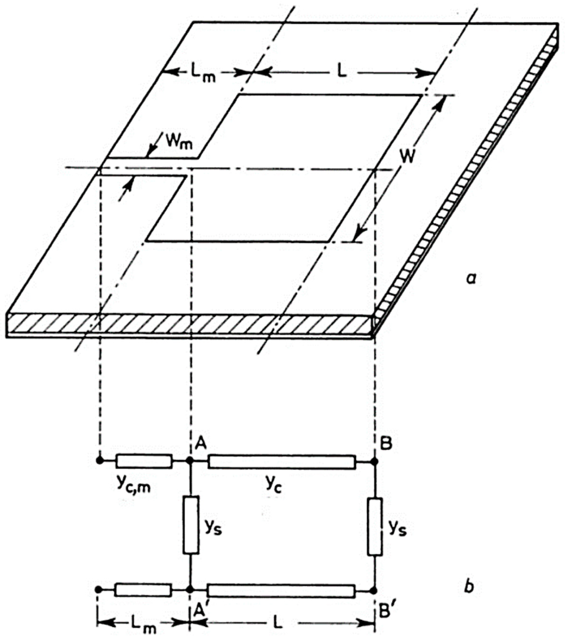
2. Transmission Line Equivalent Circuit Model of a Flexible Antenna
Bending Impacts on the Parameters and Radiation Characteristics of Flexible Antenna
3. Flexible Substrate Antenna Design
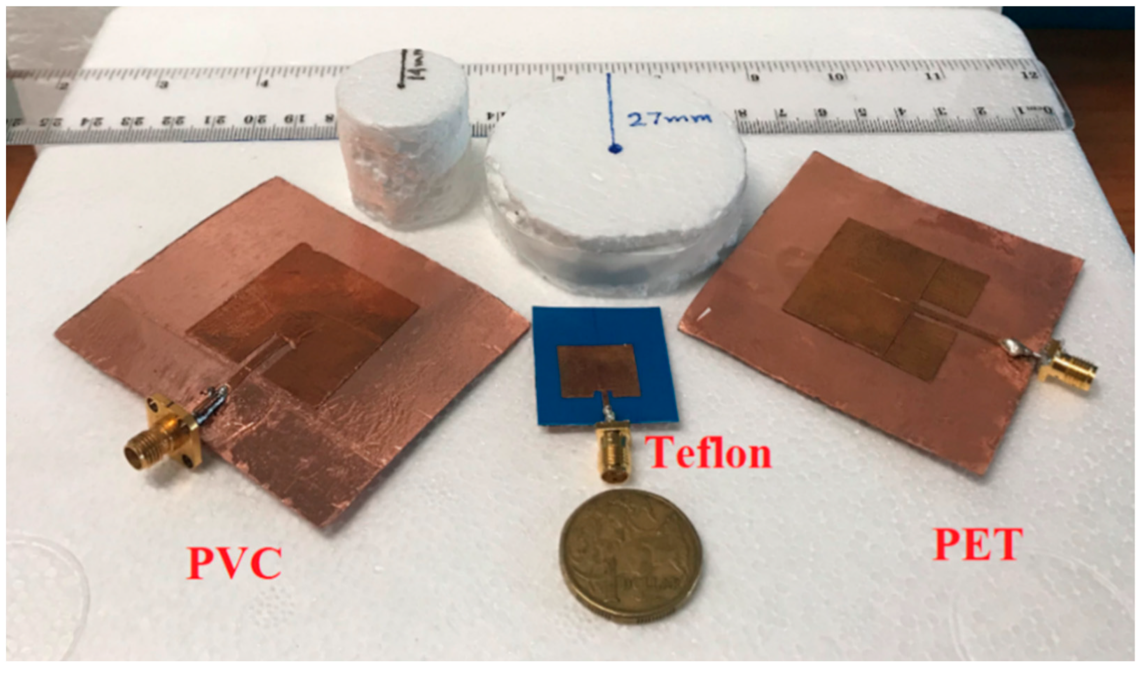
3.1. Material Selection
3.2. Property Examination
3.3. Antenna Design
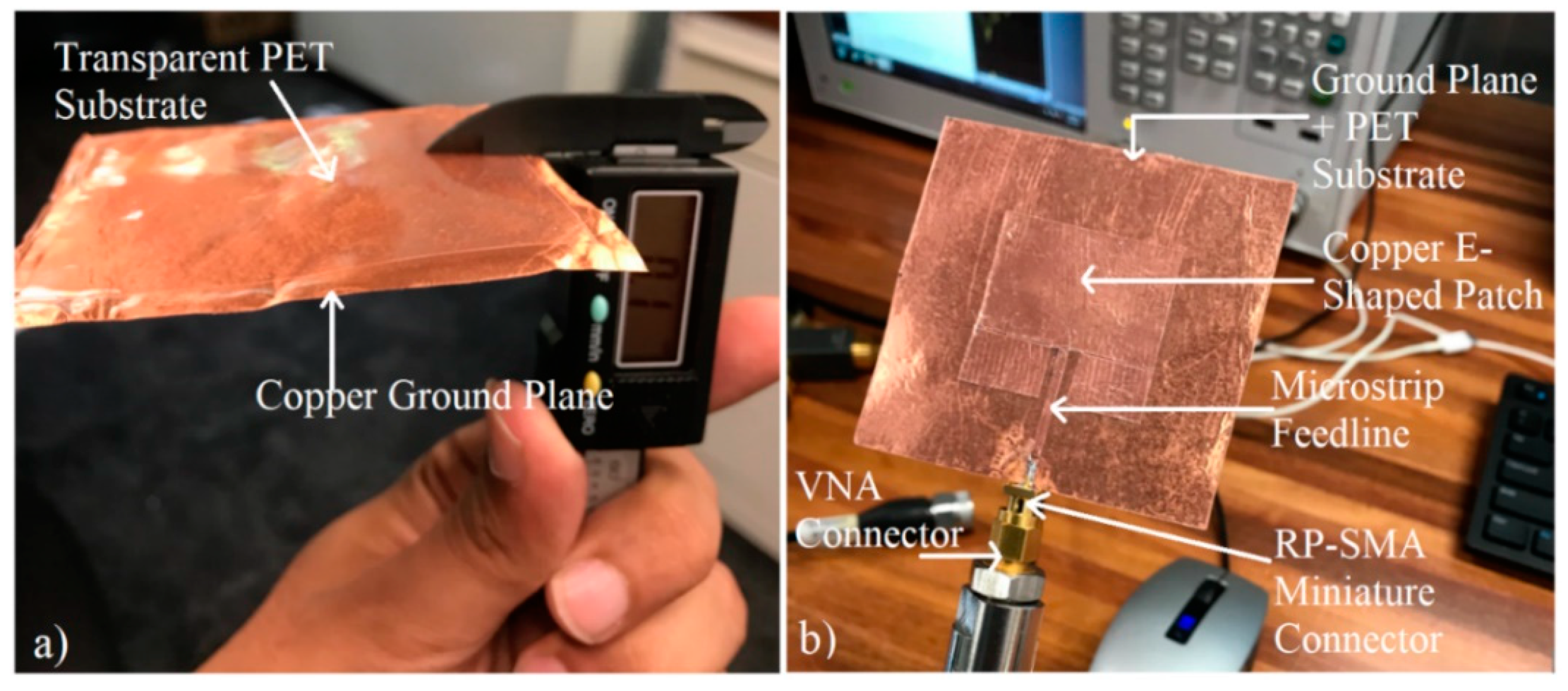
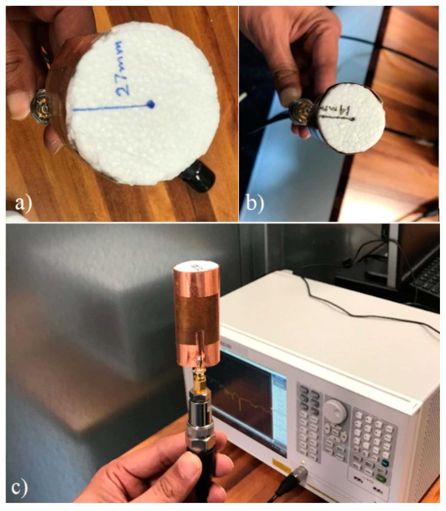
3.4. Antenna Fabrication
3.5. Measurements
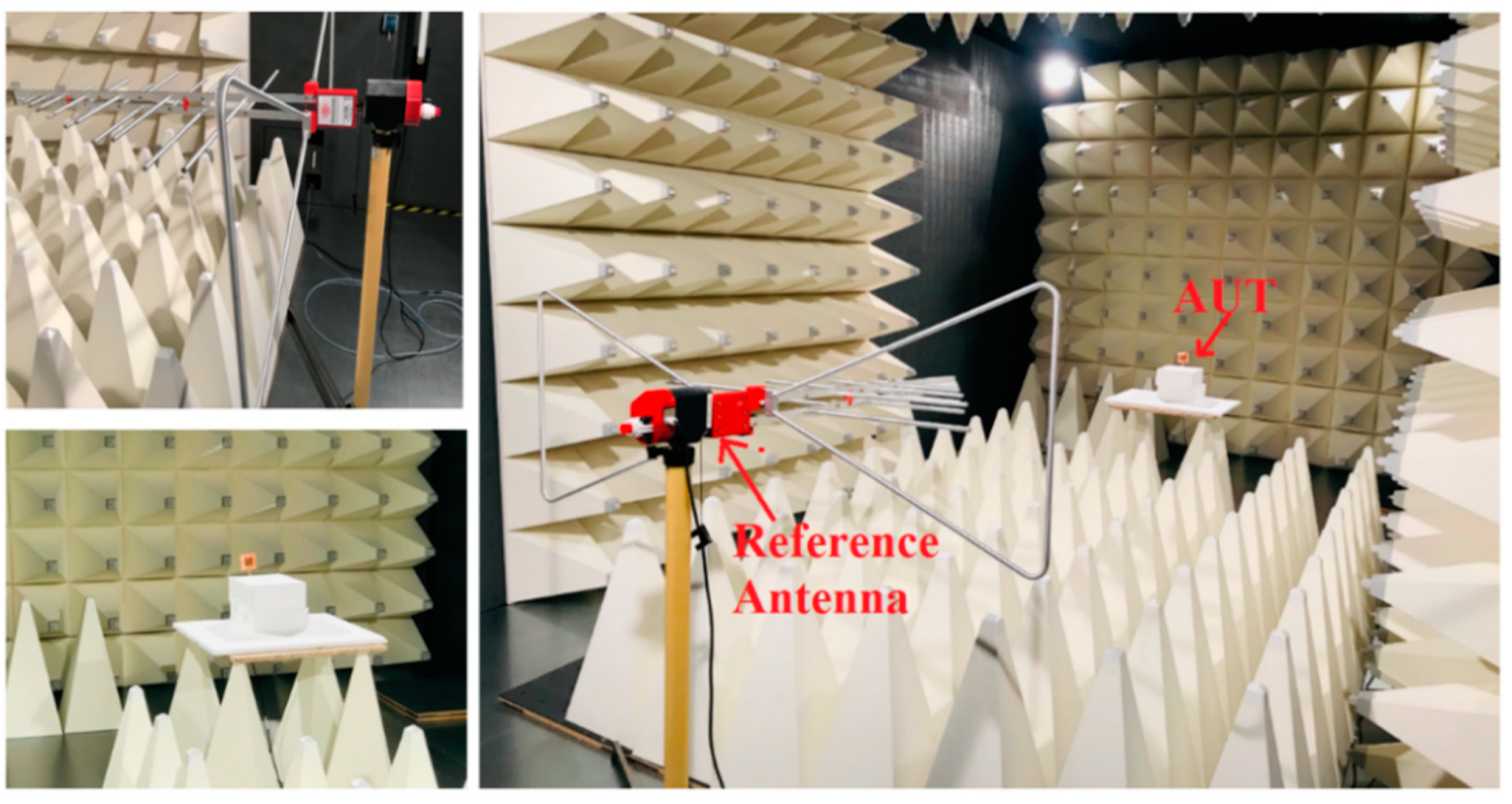
3.5.1. Introduction to the Frankonia Chamber
3.5.2. Measurements of the S-Parameters
4. Bending Analysis
4.1. Effect of Bending on Resonant Frequencies
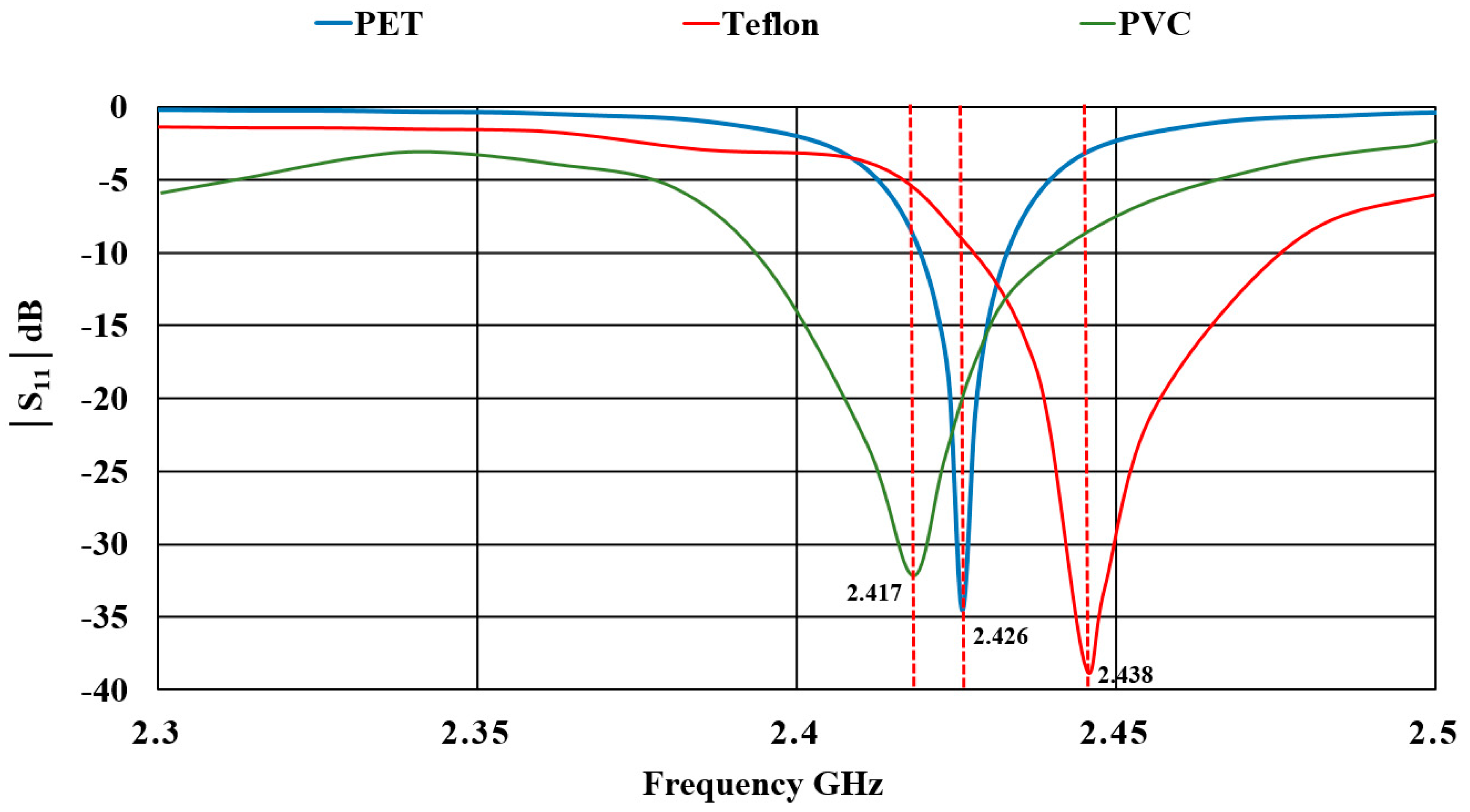
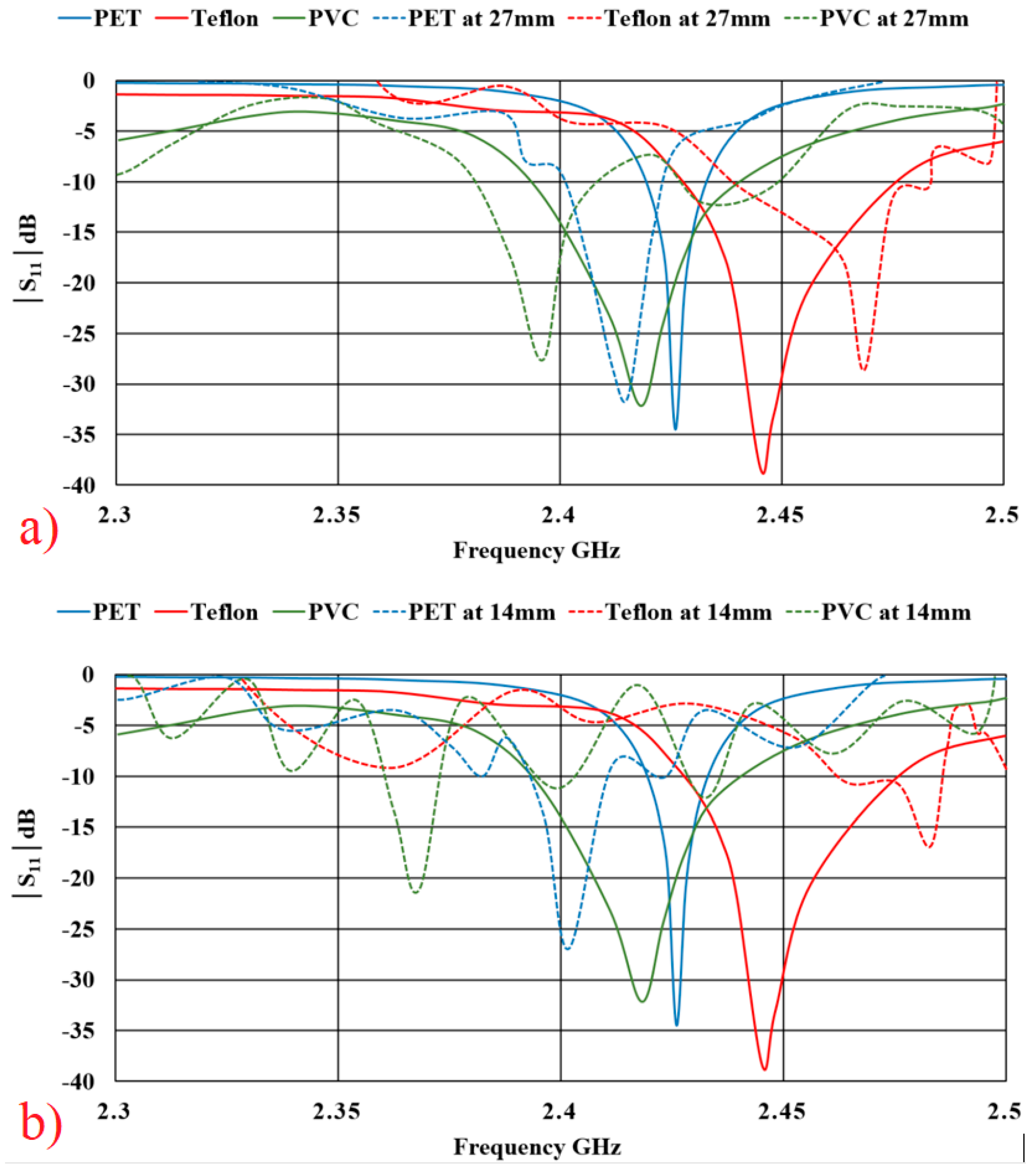
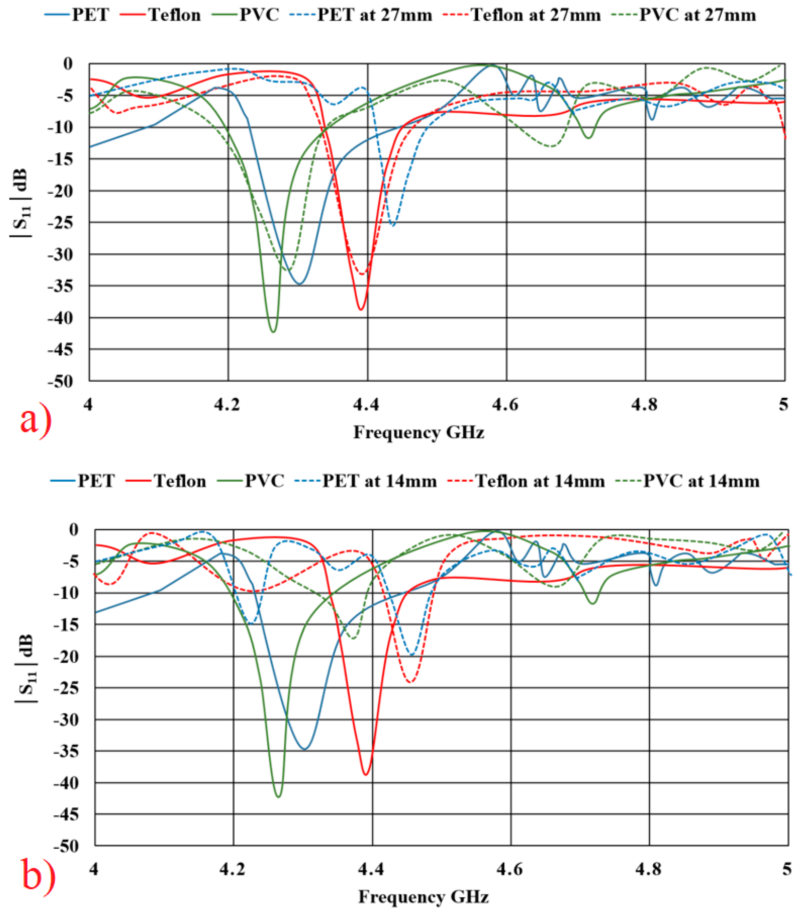
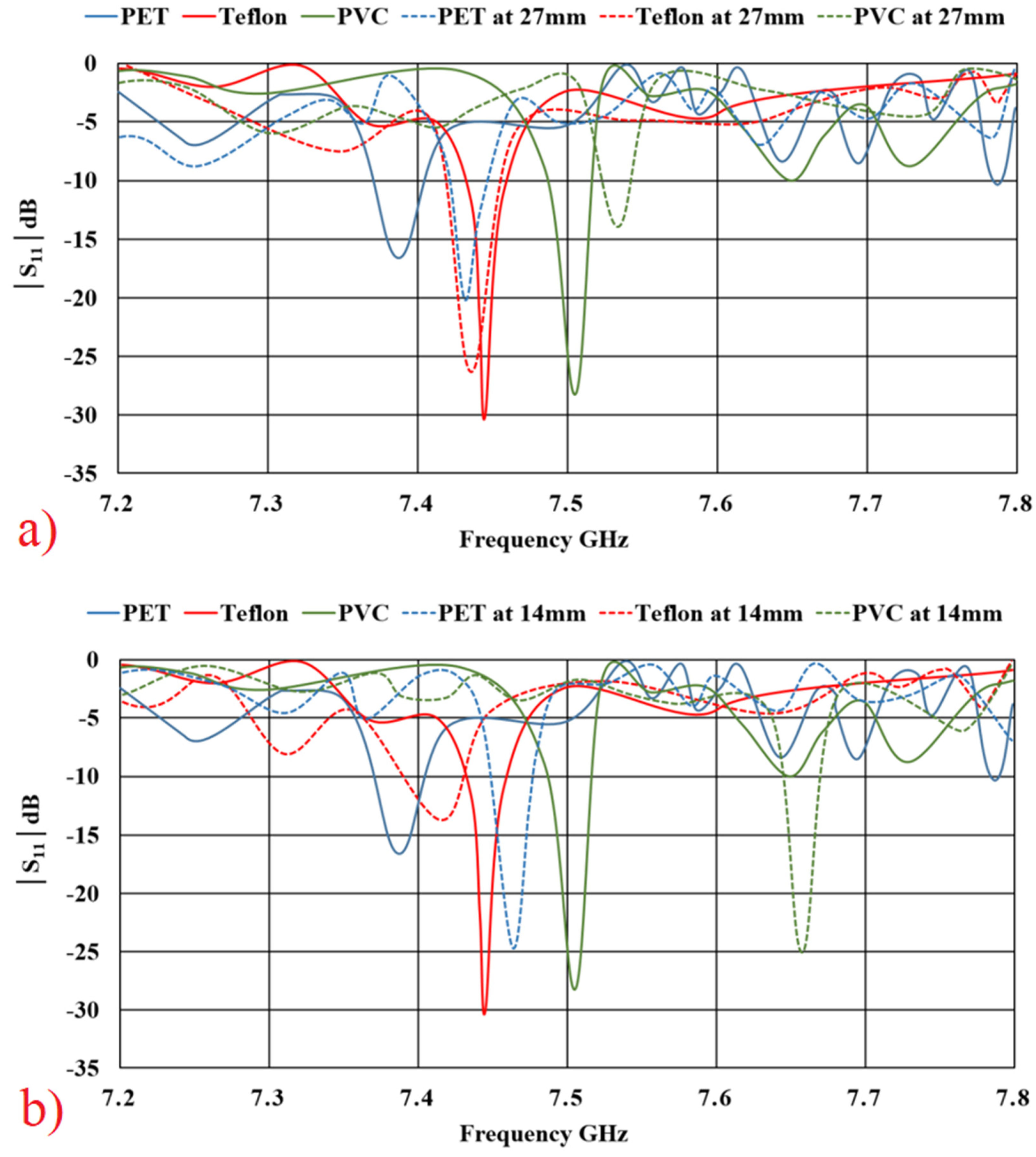
4.2. Effect of Bending on Reflection Coefficients S11
4.3. Dielectric Constant (ε) and the Resonant Frequency Shifts (%)
5. Conclusions
Author Contributions
Funding
Institutional Review Board Statement
Informed Consent Statement
Data Availability Statement
Conflicts of Interest
References
- Khan, M.A.; Raad, R.; Tubbal, F.; Theoharis, P.; Liu, S.; Foroughi, J. Bending Analysis of Polymer-Based Flexible Antennas for Wearable, General IoT Applications: A Review. Polymers 2021, 13, 357. [Google Scholar] [CrossRef]
- Khan, M.U.A.; Raad, R.; Foroughi, J. Transient Response & Electromagnetic Behaviour of Flexible Bow-Tie Shaped Chip-less RFID Tag for General IoT Applications. Adv. Sci. Technol. Eng. Syst. J. 2020, 5, 757–764. [Google Scholar] [CrossRef]
- Khan, M.U.A.; Raad, R.; Foroughi, J. A Fibre Embroidered Chipless RFID Tag on Cotton Fabrics for Wearable Applications. In Proceedings of the GLOBECOM 2020-2020 IEEE Global Communications Conference, Taipei, Taiwan, 7–11 December 2020. [Google Scholar]
- Khan, M.U.A.; Raad, R.; Foroughi, J.; Theoharis, P.I.; Liu, S.; Masud, J. A Silver-Coated Conductive Fibre HC12 Sewed Chipless RFID Tag on Cotton Fabric for Wearable Applications. In Proceedings of the 2020 IEEE 23rd International Multitopic Conference (INMIC), Bahawalpur, Pakistan, 5–7 November 2020. [Google Scholar]
- Ahmed, S.; Tahir, F.; Shamim, A.; Cheema, H. A Compact Kapton-Based Inkjet-Printed Multiband Antenna for Flexible Wireless Devices. IEEE Antennas Wirel. Propag. Lett. 2015, 14, 1802–1805. [Google Scholar] [CrossRef] [Green Version]
- Khaleel, H.R.; Al-Rizzo, H.M.; Rucker, D.G.; Mohan, S. A Compact Polyimide-Based UWB Antenna for Flexible Electronics. IEEE Antennas Wirel. Propag. Lett. 2012, 11, 564–567. [Google Scholar] [CrossRef]
- Nathan, A.; Ahnood, A.; Cole, M.; Lee, S.; Suzuki, Y.; Popat, P.H.; Bonaccorso, F.; Hasan, T.; Garcia-Gancedo, L.; Dyadyusha, A.; et al. Flexible electronics: The next ubiquitous platform. Proc. IEEE 2021. [Google Scholar] [CrossRef]
- Khan, M.U.A.; Raad, R.; Foroughi, J.; Raheel, M.S.; Houshyar, S. An octagonal-shaped conductive HC12 & LIBERATOR-40 thread embroidered chipless RFID for general IoT applications. Sens. Actuators A Phys. 2020, 318, 112485. [Google Scholar] [CrossRef]
- Hwang, B.; Lund, A.; Tian, Y.; Darabi, S.; Müller, C. Machine-Washable Conductive Silk Yarns with a Composite Coating of Ag Nanowires and PEDOT:PSS. ACS Appl. Mater. Interfaces 2020, 12, 27537–27544. [Google Scholar] [CrossRef]
- Khaleel, H.R.; Al-Rizzo, H.M.; Rucker, D.G. Compact Polyimide-Based Antennas for Flexible Displays. J. Disp. Technol. 2012, 8, 91–97. [Google Scholar] [CrossRef]
- Khan, M.U.A.; Raad, R.; Foroughi, J.; Tubbal, F.; Theoharis, P.I.; Raheel, M.S. Effects of Bending Bow-Tie Chipless RFID Tag for Different Polymer Substrates. In Proceedings of the 2019 13th International Conference on Signal Processing and Communication Systems (ICSPCS), Gold Coast, Australia, 16–18 December 2019. [Google Scholar]
- Khaleel, H. Innovation in Wearable and Flexible Antennas; Wit Press: Southampton, UK, 2014. [Google Scholar]
- Kornek, D.; Lottke, E.; Orlob, C.; Rolfes, I. Experimental investigation of bent patch antennas on MID substrate. In Proceedings of the Fourth European Conference on Antennas and Propagation, Barcelona, Spain, 12–16 April 2010. [Google Scholar]
- Zinke, O.; Brunswig, H. Halbleiter, Halbleiterbauelemente und Elektronenröhren, in Hochfrequenztechnik; Springer: Berlin/Heidelberg, Germany, 1999; pp. 1–203. [Google Scholar]
- Khan, M.U.A.; Raad, R.; Foroughi, J.; Tubbal, F.E.; Xi, J. Novel Bow-Tie Chip-less RFID Tag for Wearable Applications. In Proceedings of the 2019 19th International Symposium on Communications and Information Technologies (ISCIT), Ho Chi Minh City, Vietnam, 25–27 September 2019. [Google Scholar]
- Mustafa, F.; Khan, U.A.; Anjum, M.R.; Hussain, S. Triple H-shaped multiple band frequency reconfigurable patch antenna. In Proceedings of the Innovative Computing Technology (INTECH), 2016 Sixth International Conference on, Dublin, Ireland, 24–26 August 2016. [Google Scholar]
- Qiu, Y.; Jung, Y.H.; Lee, S.; Shih, T.-Y.; Lee, J.; Xu, Y.H.; Xu, R.; Lin, W.; Behdad, N.; Ma, Z. Compact parylene-c-coated flexible antenna for WLAN and upper-band UWB applications. Electron. Lett. 2014, 50, 1782–1784. [Google Scholar] [CrossRef]
- Hamouda, Z.; Wojkiewicz, J.-L.; Pud, A.A.; Kone, L.; Belaabed, B.; Bergheul, S.; Lasri, T. Dual-Band Elliptical Planar Conductive Polymer Antenna Printed on a Flexible Substrate. IEEE Trans. Antennas Propag. 2015, 63, 5864–5867. [Google Scholar] [CrossRef]
- Trajkovikj, J.; Zürcher, J.-F.; Skrivervik, A.K. PDMS, a robust casing for flexible W-BAN antennas [EurAAP corner]. IEEE Antennas Propag. Mag. 2013, 55, 287–297. [Google Scholar] [CrossRef]
- Lin, C.-P.; Chang, C.-H.; Cheng, Y.T.; Jou, C.F. Development of a Flexible SU-8/PDMS-Based Antenna. IEEE Antennas Wirel. Propag. Lett. 2011, 10, 1108–1111. [Google Scholar] [CrossRef]
- Takao, S. Stretchable Electronics; Wiley-VCH: Weinheim, Germany, 2013; pp. 484–485. [Google Scholar]
- Catalogue, G. Metals, Alloys, Compounds, Ceramics, Polymers. Composites; GoodfellowMetals: Cambridge, UK, 1993. [Google Scholar]
- Kim, S.; Yun, T.G.; Kang, C.; Son, M.-J.; Kang, J.-G.; Kim, I.-H.; Lee, H.-J.; An, C.-H.; Hwang, B. Facile fabrication of paper-based silver nanostructure electrodes for flexible printed energy storage system. Mater. Des. 2018, 151, 1–7. [Google Scholar] [CrossRef]
- Hertleer, C.; Tronquo, A.; Rogier, H.; Vallozzi, L.; van Langenhove, L. Aperture-Coupled Patch Antenna for Integration Into Wearable Textile Systems. IEEE Antennas Wirel. Propag. Lett. 2007, 6, 392–395. [Google Scholar] [CrossRef] [Green Version]
- Pavuluri, S.K.; Wang, C.; Sangster, A.J. High Efficiency Wideband Aperture-Coupled Stacked Patch Antennas Assembled Using Millimeter Thick Micromachined Polymer Structures. IEEE Trans. Antennas Propag. 2010, 58, 3616–3621. [Google Scholar] [CrossRef]
- Pavuluri, S.; Wang, C.; Sangster, A. A High-Performance Aperture-Coupled Patch Antenna Supported by a Micromachined Polymer Ring. IEEE Antennas Wirel. Propag. Lett. 2008, 7, 283–286. [Google Scholar] [CrossRef]
- Michel, A.; Colella, R.; Casula, G.A.; Nepa, P.; Catarinucci, L.; Montisci, G.; Mazzarella, G.; Manara, G. Design Considerations on the Placement of a Wearable UHF-RFID PIFA on a Compact Ground Plane. IEEE Trans. Antennas Propag. 2018, 66, 3142–3147. [Google Scholar] [CrossRef]
- Yan, S.; Volskiy, V.; Vandenbosch, G.A. Compact dual-band textile PIFA for 433-MHz/2.4-GHz ISM bands. IEEE Antennas Wirel. Propag. Lett. 2017, 16, 2436–2439. [Google Scholar] [CrossRef]
- Wang, L.; Guo, Y.; Salam, B.; Lu, C.W.A. A flexible modified dipole antenna printed on PET film. In Proceedings of the Antennas and Propagation (APCAP), 2012 IEEE Asia-Pacific Conference on, Singapore, 27–29 August 2012. [Google Scholar]
- Scarpello, M.L.; Kurup, D.; Rogier, H.; Ginste, D.V.; Axisa, F.; Vanfleteren, J.; Joseph, W.; Martens, L.; Vermeeren, G. Design of an Implantable Slot Dipole Conformal Flexible Antenna for Biomedical Applications. IEEE Trans. Antennas Propag. 2011, 59, 3556–3564. [Google Scholar] [CrossRef] [Green Version]
- Jung, J.; Lee, H.; Lim, Y. Broadband flexible comb-shaped monopole antenna. IET Microw. Antennas Propag. 2009, 3, 325–332. [Google Scholar] [CrossRef]
- Salonen, P.; Kim, J.; Rahmat-Samii, Y. Dual-band E-shaped patch wearable textile antenna. In Proceedings of the 2005 IEEE Antennas and Propagation Society International Symposium, Washington, DC, USA, 3–8 July 2005. [Google Scholar]
- Tubbal, F.; Raad, R.; Theoharis, R.I.; Iranmanesh, S.; Abulgase, S.; Khan, M.U.A. Dual Band Slot Antenna with F-Shaped Slits for C-band and X-band Applications. In Proceedings of the 2019 13th International Conference on Signal Processing and Communication Systems (ICSPCS), Gold Coast, QLD, Australia, 16–18 December 2019. [Google Scholar]
- Kiourti, A.; Volakis, J.L. Stretchable and Flexible E-Fiber Wire Antennas Embedded in Polymer. IEEE Antennas Wirel. Propag. Lett. 2014, 13, 1381–1384. [Google Scholar] [CrossRef]
- Liu, H.; Zhu, S.; Wen, P.; Xiao, X.; Che, W.; Guan, X. Flexible CPW-Fed Fishtail-Shaped Antenna for Dual-Band Applications. IEEE Antennas Wirel. Propag. Lett. 2014, 13, 770–773. [Google Scholar] [CrossRef]
- Du, C.-z.; Zhu, L.-x.; Yang, Z.-p.; Wang, X.; Liu, H.-y.; Nie, Y. A CPW-fed UWB Flexible Antenna with Double Band-notched Characteristics. In Proceedings of the 2019 IEEE 19th International Conference on Communication Technology (ICCT), Xi’an, China, 16–19 October 2019. [Google Scholar]
- Sallam, M.O.; Kandil, S.M.; Volski, V.; VandenBosch, G.A.E.; Soliman, E.A. Wideband CPW-Fed Flexible Bow-Tie Slot Antenna for WLAN/WiMax Systems. IEEE Trans. Antennas Propag. 2017, 65, 4274–4277. [Google Scholar] [CrossRef]
- Castro, A.T.; Sharma, S.K. Inkjet-Printed Wideband Circularly Polarized Microstrip Patch Array Antenna on a PET Film Flexible Substrate Material. IEEE Antennas Wirel. Propag. Lett. 2017, 17, 176–179. [Google Scholar] [CrossRef]
- Ha, S.-J.; Jung, C.W. Reconfigurable Beam Steering Using a Microstrip Patch Antenna With a U-Slot for Wearable Fabric Applications. IEEE Antennas Wirel. Propag. Lett. 2011, 10, 1228–1231. [Google Scholar] [CrossRef]
- Hayes, G.J.; So, J.-H.; Qusba, A.; Dickey, M.; Lazzi, G. Flexible Liquid Metal Alloy (EGaIn) Microstrip Patch Antenna. IEEE Trans. Antennas Propag. 2012, 60, 2151–2156. [Google Scholar] [CrossRef]
- Locher, I.; Klemm, M.; Kirstein, T.; Troster, G. Design and Characterization of Purely Textile Patch Antennas. IEEE Trans. Adv. Packag. 2006, 29, 777–788. [Google Scholar] [CrossRef] [Green Version]
- Quarfoth, R.; Zhou, Y.; Sievenpiper, D. Flexible Patch Antennas Using Patterned Metal Sheets on Silicone. IEEE Antennas Wirel. Propag. Lett. 2015, 14, 1-1. [Google Scholar] [CrossRef]
- Verma, A.; Weng, B.; Shepherd, R.; Fumeaux, C.; Truong, V.-T.; Wallace, G.; Bates, B.D. 6 GHz microstrip patch antennas with PEDOT and polypyrrole conducting polymers. In Proceedings of the 2010 International Conference on Electromagnetics in Advanced Applications, Sydney, NSW, Australia, 20–24 September 2010. [Google Scholar]
- Balanis, C. Antenna Theory Analysis and Design, 3rd ed.; John Wilen & Sons, Inc.: Hoboken, NJ, USA, 2005. [Google Scholar]


| Properties of Pure Copper [20] | |||||||
|---|---|---|---|---|---|---|---|
| Physical | Electrical | Mechanical | Thermal | ||||
| Melting Point | Density | Conductivity | Temperature Coefficient | Tensile Strength | Modulus | Thermal Conductivity | CTE |
| 1083 °C | 8.96 g/cm3 at 20 °C | 58 MS/m at 20 °C | 0.0043/K at 0–100 °C | 224–314 MPa | 137.8 | 401 W/m-K at 0–100 °C | 17.0 × 10⁻⁶ m/m-K at 0–100 °C |
| Substrate | Model/ Thickness | Physical/Mechanical Properties | Electrical Properties | Thermal/Chemical Properties | ||||||
|---|---|---|---|---|---|---|---|---|---|---|
| Density (g/cc) | Tensile Strength X-Direction at 23 °C (Kpsi) | Tensile Modulus X-Direction at 23 °C (Kpsi) | Dielectric Constants 100 Hz to 1 GHz | Dielectric Strength (V/mil) | Dissipation Factor Tan σ at 100 Hz to 1 GHz | CTE-15 °C to 300 °C (ppm/C) | Moisture Absorption (%) at 23 °C | Shrinkage (%) 30 min, 150 °C | ||
| PET | Melinex 401 Polyester 70 μm | 1.3 | 25 | 420 | 2.07 | 4000 | 0.002 | 19 to 20 | 0.1 to 0.7 | 0.5 to 1.1 |
| PTFE | Teflon 100 μm | 2.1 | 3.9 | 65 | 2.70 | 285 | 0.0002 | 250 to 275 | 0 to 0.05 | 1.5 to 3.0 |
| PVC | Flexible PVC-O 110 μm | 1.4 | 2.2 | 217 | 3.70 | 635 | 0.04 | 6 to 7 | 0.2 to 1 | 0.2 to 2 |
| Resonant Frequency (GHz) | Substrates | PET | PTFE | PVC | |
| Operating at 2.45 GHz | Flat | 2.426 | 2.438 | 2.417 | |
| 27 mm | 2.412 | 2.469 | 2.394 | ||
| Shift (%) | −0.58 | 1.25 | −0.96 | ||
| 14 mm | 2.402 | 2.484 | 2.366 | ||
| Shift (%) | −0.99 | 1.85 | −3.42 | ||
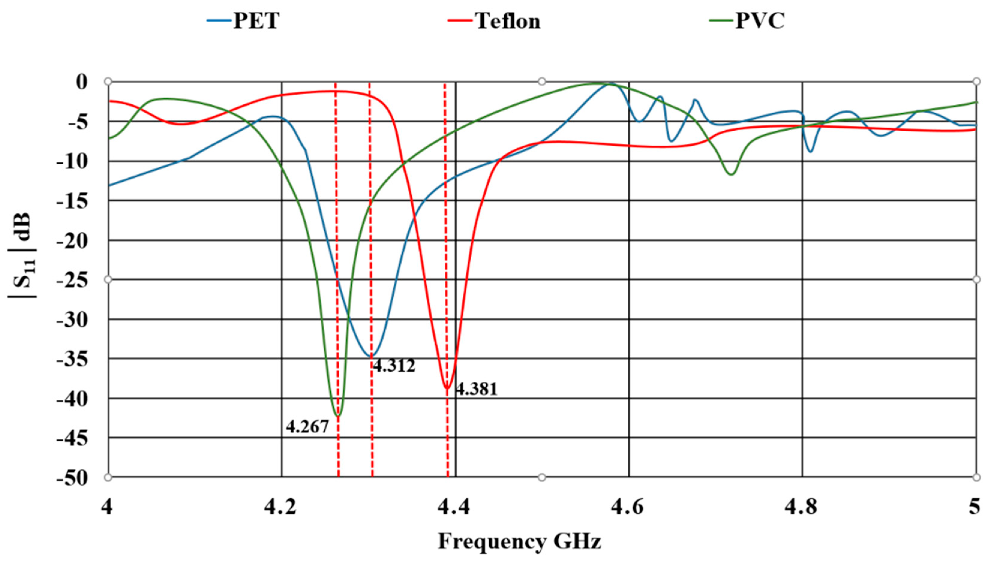
| Operating at 4.25 GHz | Flat | 4.312 | 4.381 | 4.267 | |
| 27 mm | 4.442 | 4.392 | 4.294 | ||
| Shift (%) | 2.92 | 0.25 | 0.62 | ||
| 14 mm | 4.468 | 4.453 | 4.366 | ||
| Shift (%) | 3.49 | 1.61 | 2.26 | ||
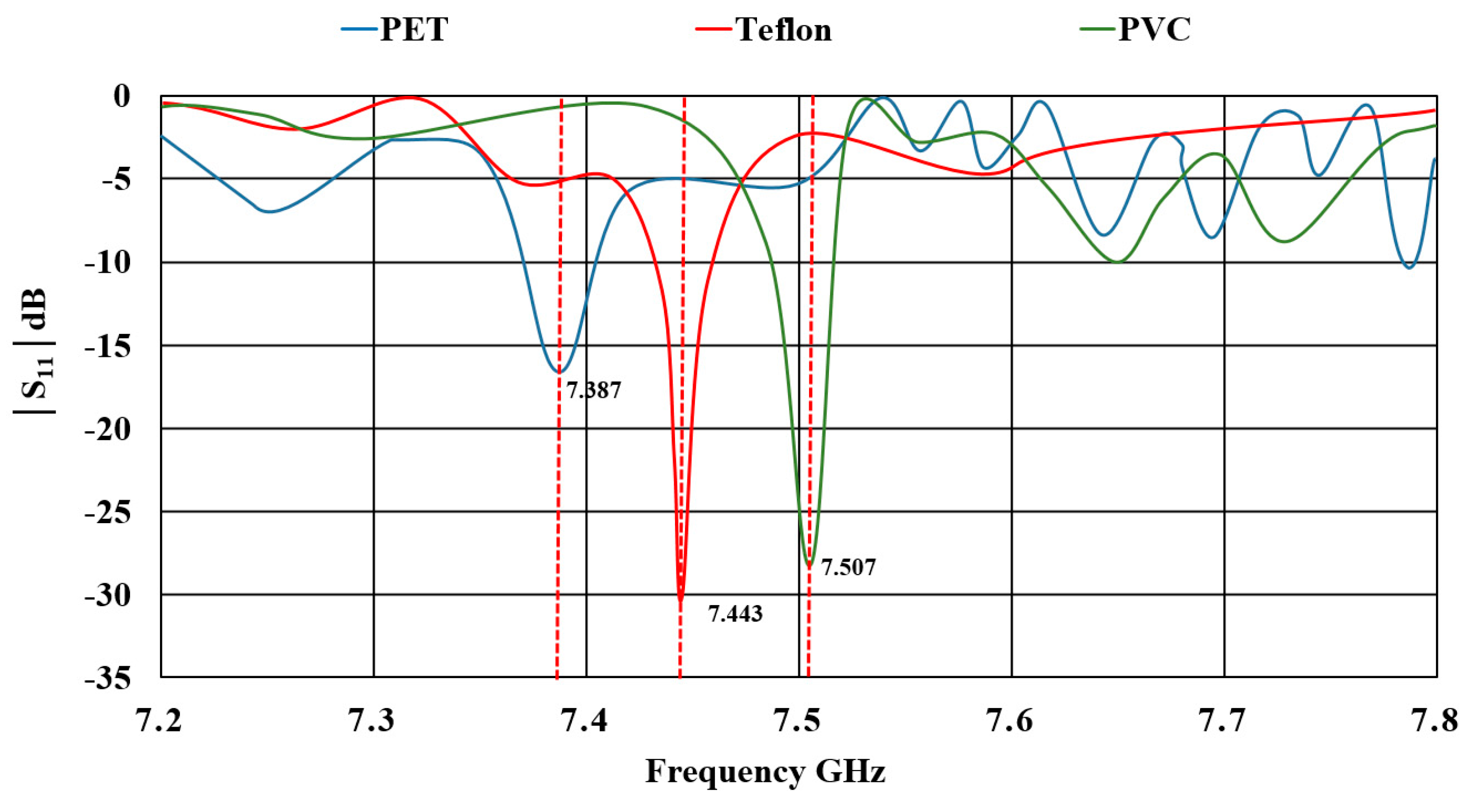
| Operating at 7.45 GHz | Flat | 7.387 | 7.443 | 7.507 | |
| 27 mm | 7.425 | 7.429 | 7.541 | ||
| Shift (%) | 0.51 | −0.01 | 0.45 | ||
| 14 mm | 7.464 | 7.421 | 7.658 | ||
| Shift (%) | 1.03 | −0.29 | 1.97 | ||
Publisher’s Note: MDPI stays neutral with regard to jurisdictional claims in published maps and institutional affiliations. |
© 2021 by the authors. Licensee MDPI, Basel, Switzerland. This article is an open access article distributed under the terms and conditions of the Creative Commons Attribution (CC BY) license (https://creativecommons.org/licenses/by/4.0/).
Share and Cite
Khan, M.U.A.; Raad, R.; Tubbal, F.; Ioannis Theoharis, P. The Impact of Bending on Radiation Characteristics of Polymer-Based Flexible Antennas for General IoT Applications. Appl. Sci. 2021, 11, 9044. https://doi.org/10.3390/app11199044
Khan MUA, Raad R, Tubbal F, Ioannis Theoharis P. The Impact of Bending on Radiation Characteristics of Polymer-Based Flexible Antennas for General IoT Applications. Applied Sciences. 2021; 11(19):9044. https://doi.org/10.3390/app11199044
Chicago/Turabian StyleKhan, Muhammad Usman Ali, Raad Raad, Faisel Tubbal, and Panagiotis Ioannis Theoharis. 2021. "The Impact of Bending on Radiation Characteristics of Polymer-Based Flexible Antennas for General IoT Applications" Applied Sciences 11, no. 19: 9044. https://doi.org/10.3390/app11199044
APA StyleKhan, M. U. A., Raad, R., Tubbal, F., & Ioannis Theoharis, P. (2021). The Impact of Bending on Radiation Characteristics of Polymer-Based Flexible Antennas for General IoT Applications. Applied Sciences, 11(19), 9044. https://doi.org/10.3390/app11199044