
Deformation Behavior of Saturated Soft Clay under Cyclic Loading with Principal Stress Rotation


Abstract
:1. Introduction
2. Specimen Preparation and Test Apparatus
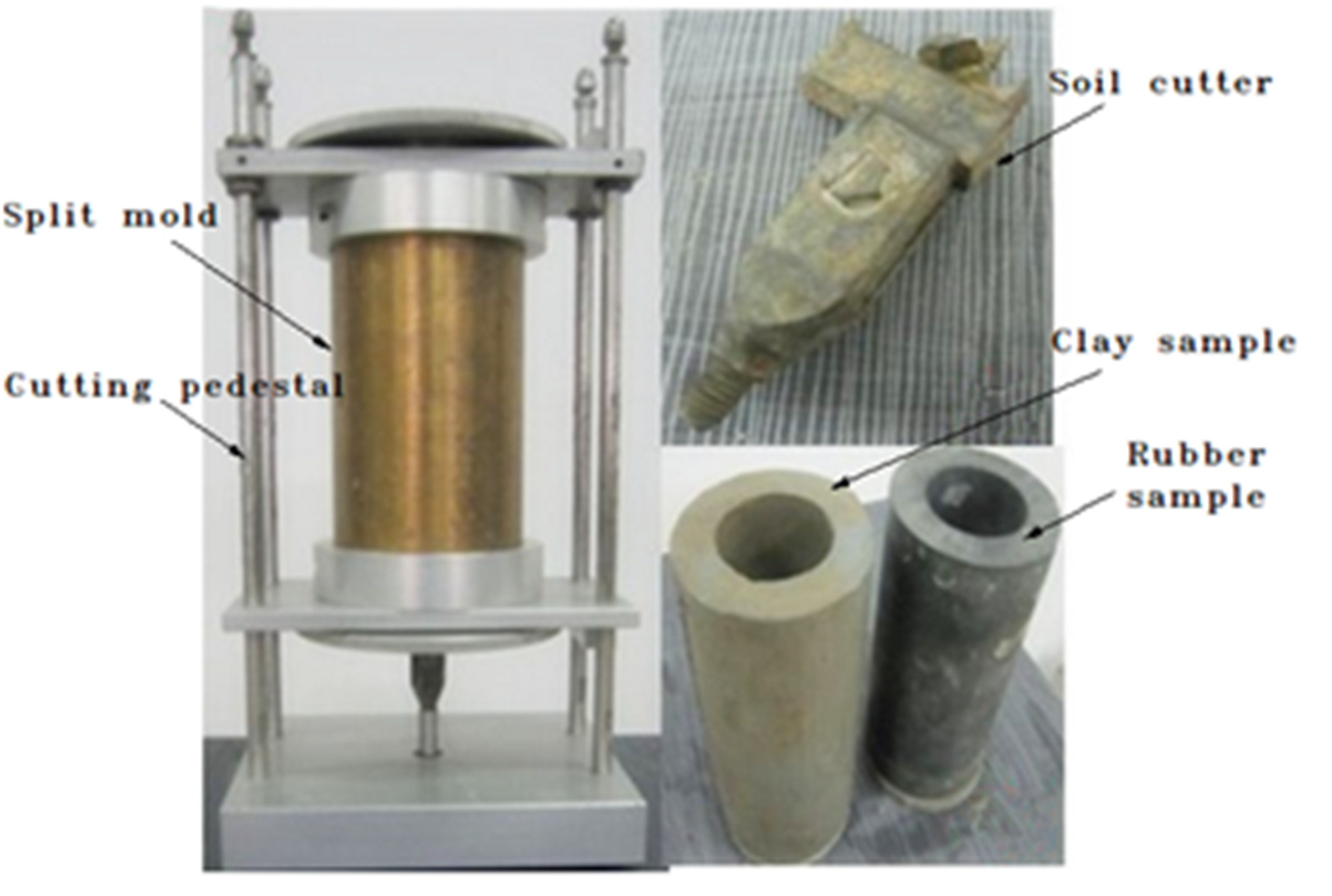
2.1. Sampling Methods
2.2. Test Apparatus
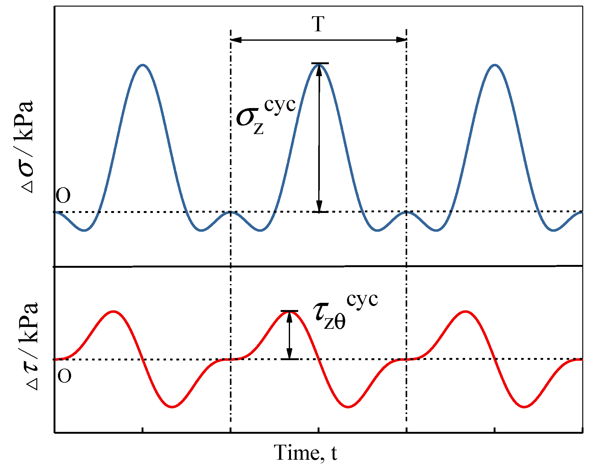
3. Test Procedure
4. Test Results and Discussion
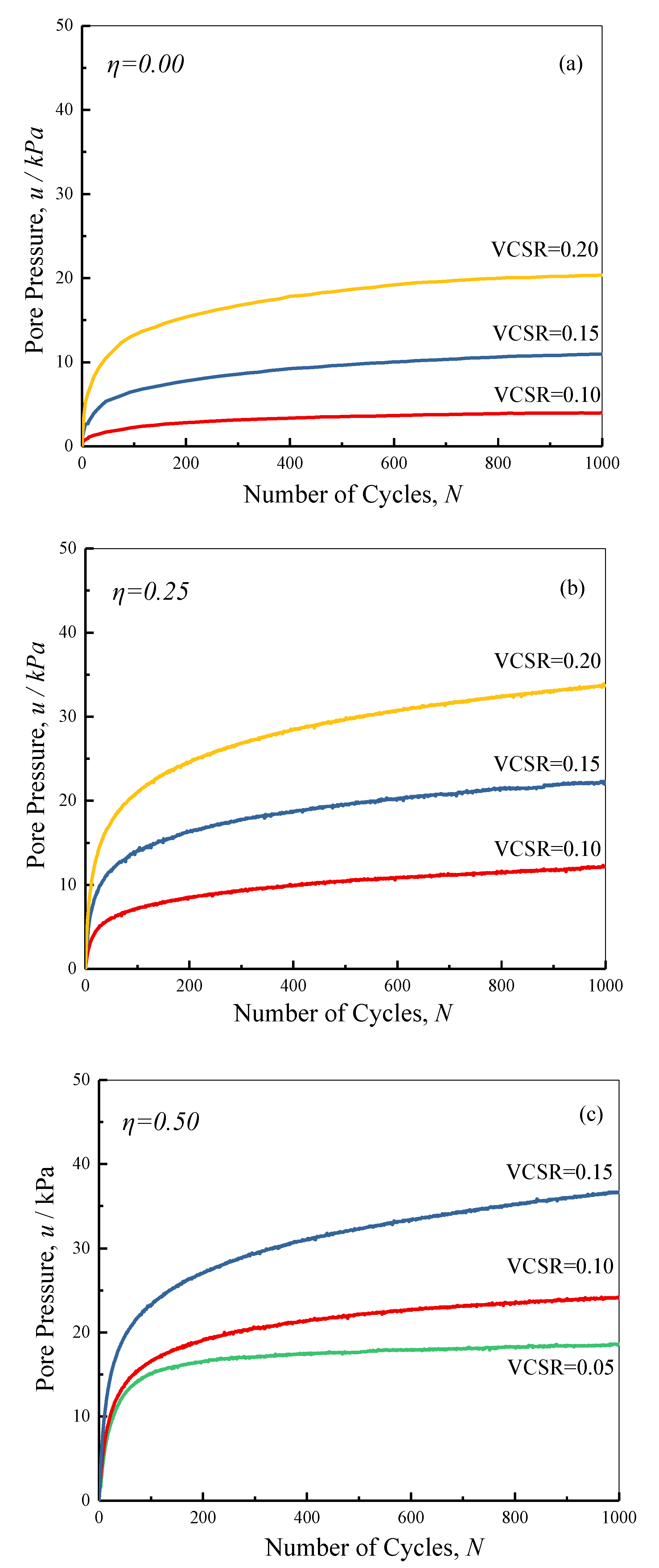
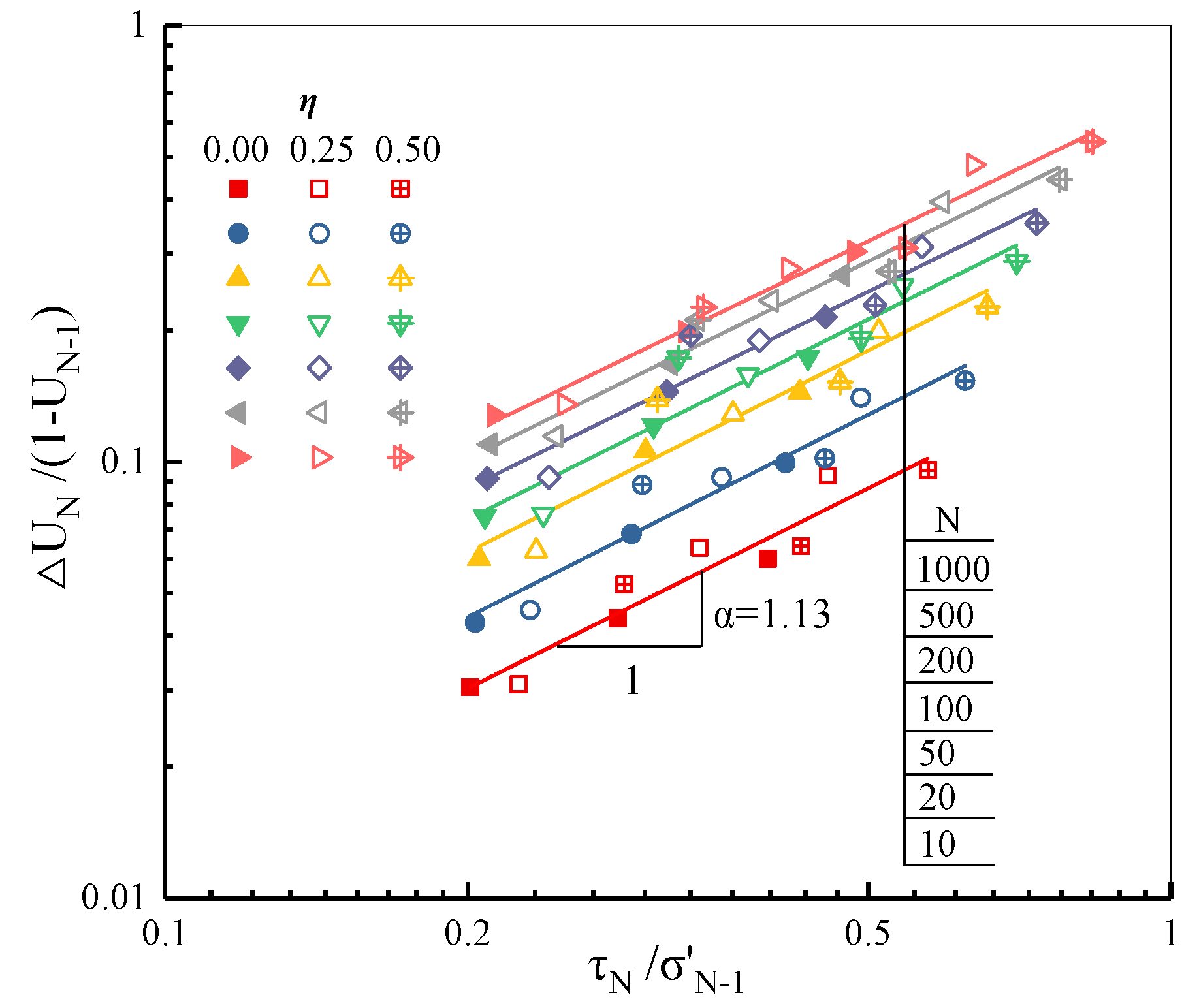
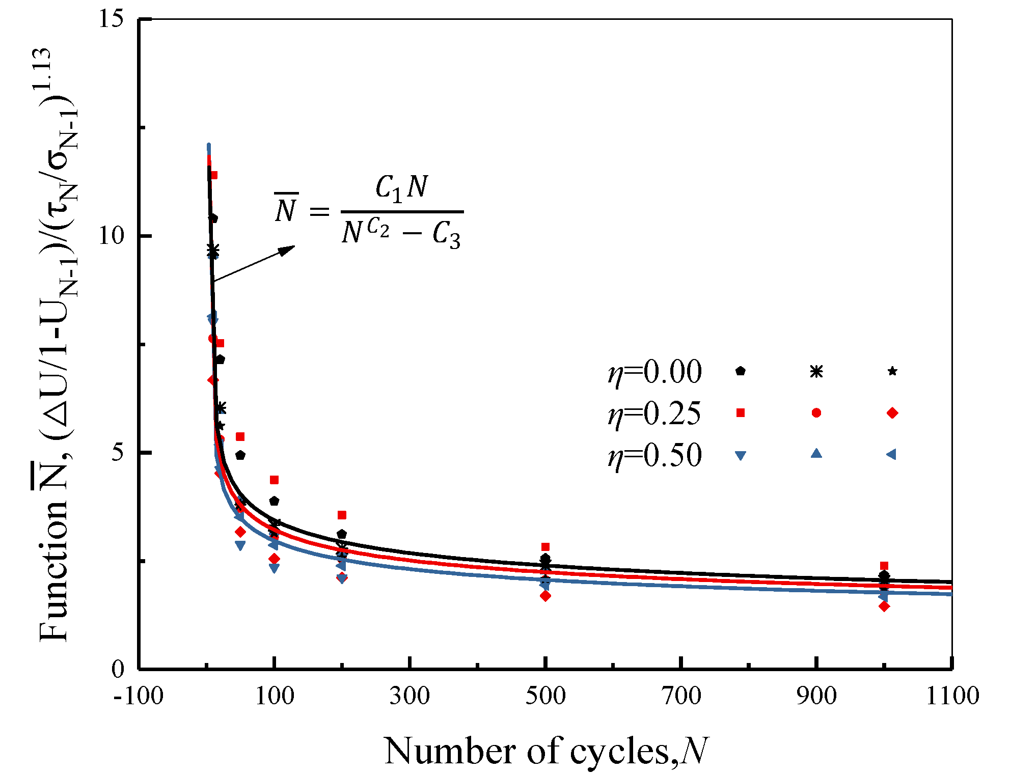
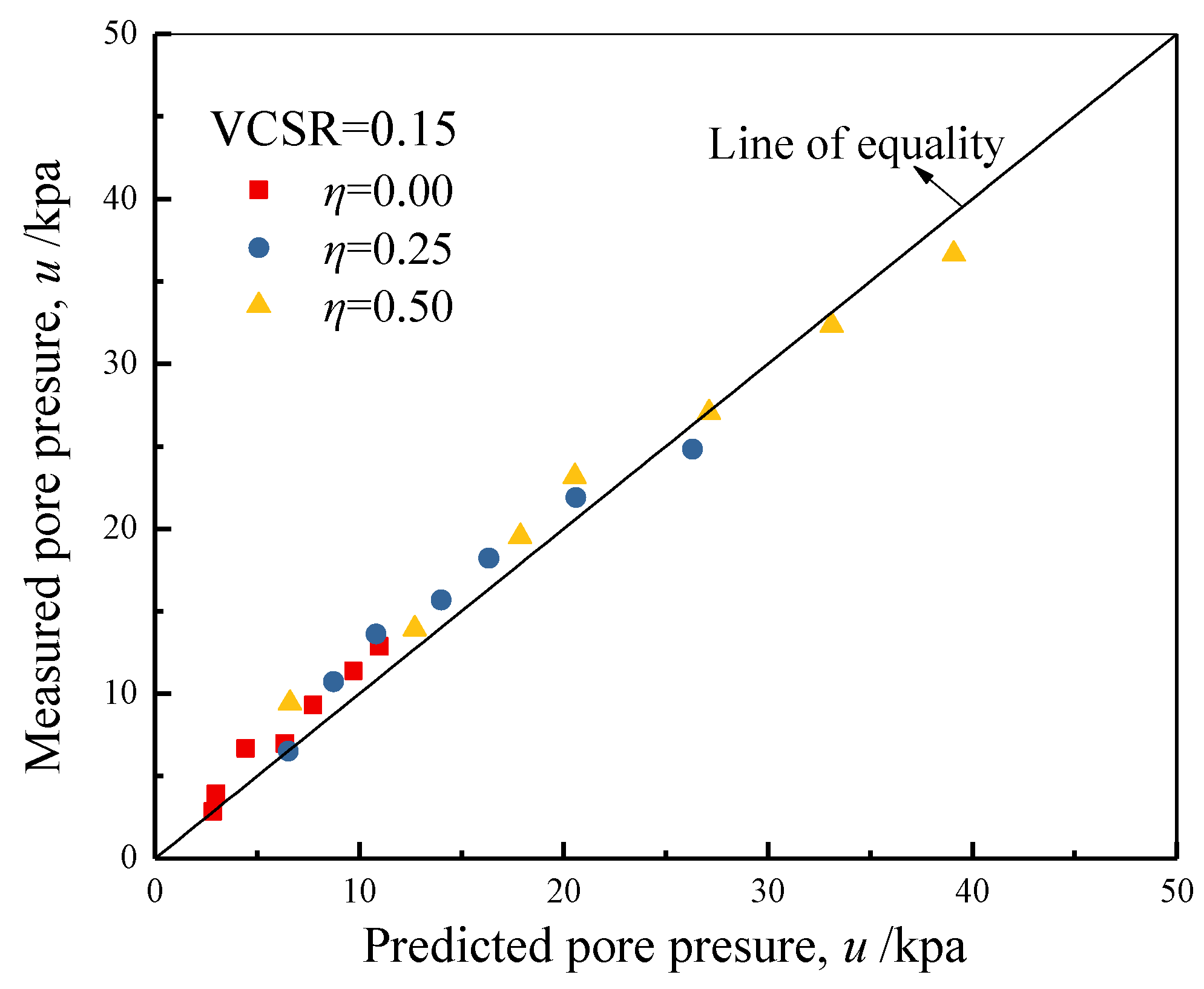
4.1. Pore Pressure
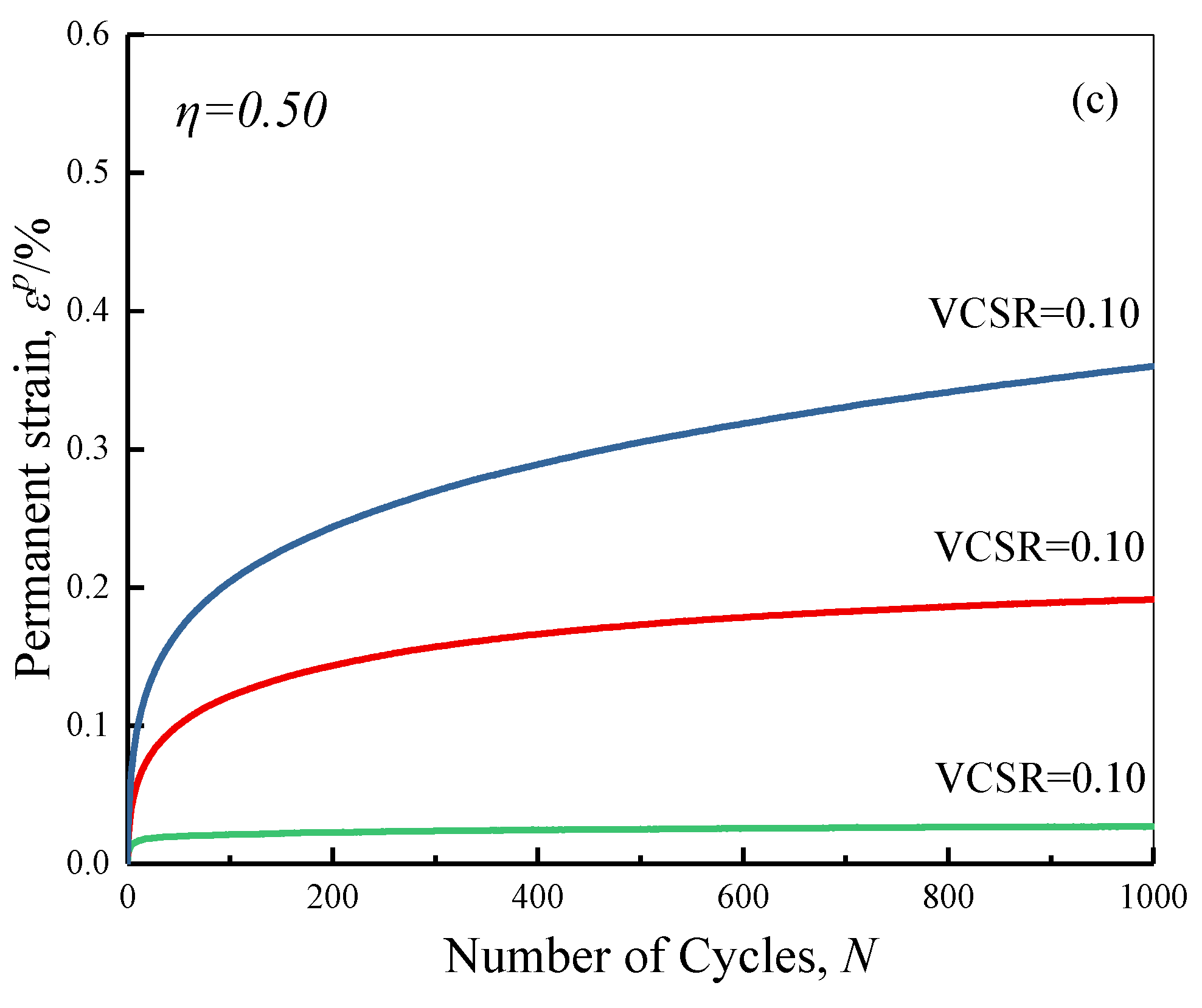
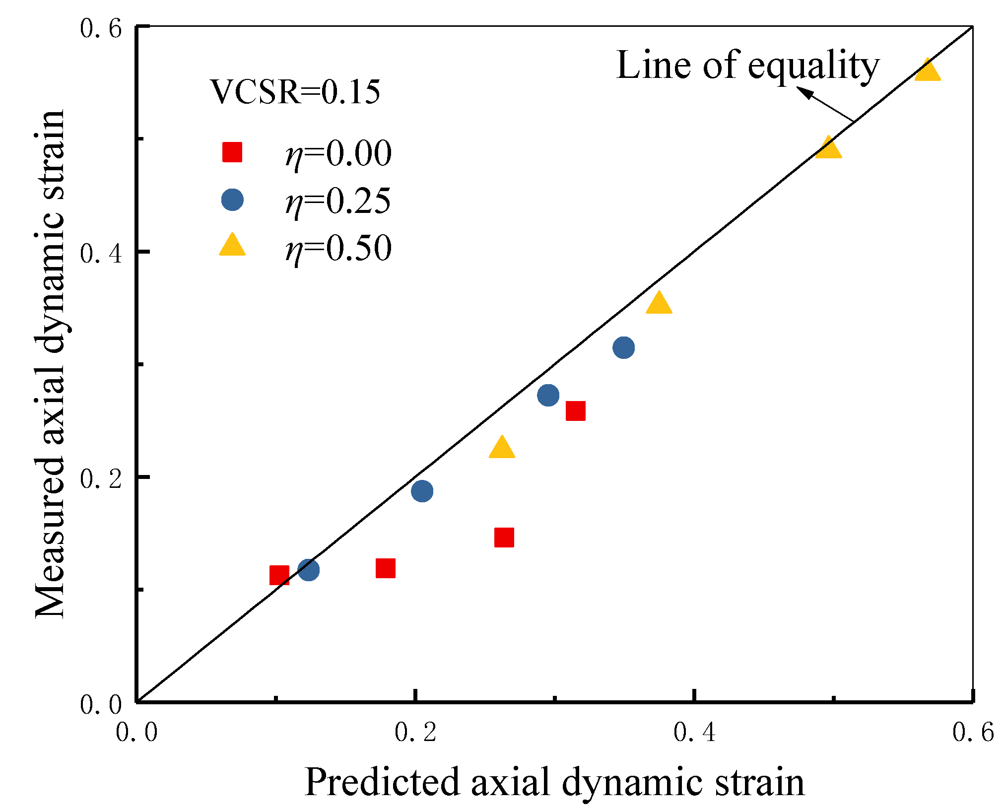
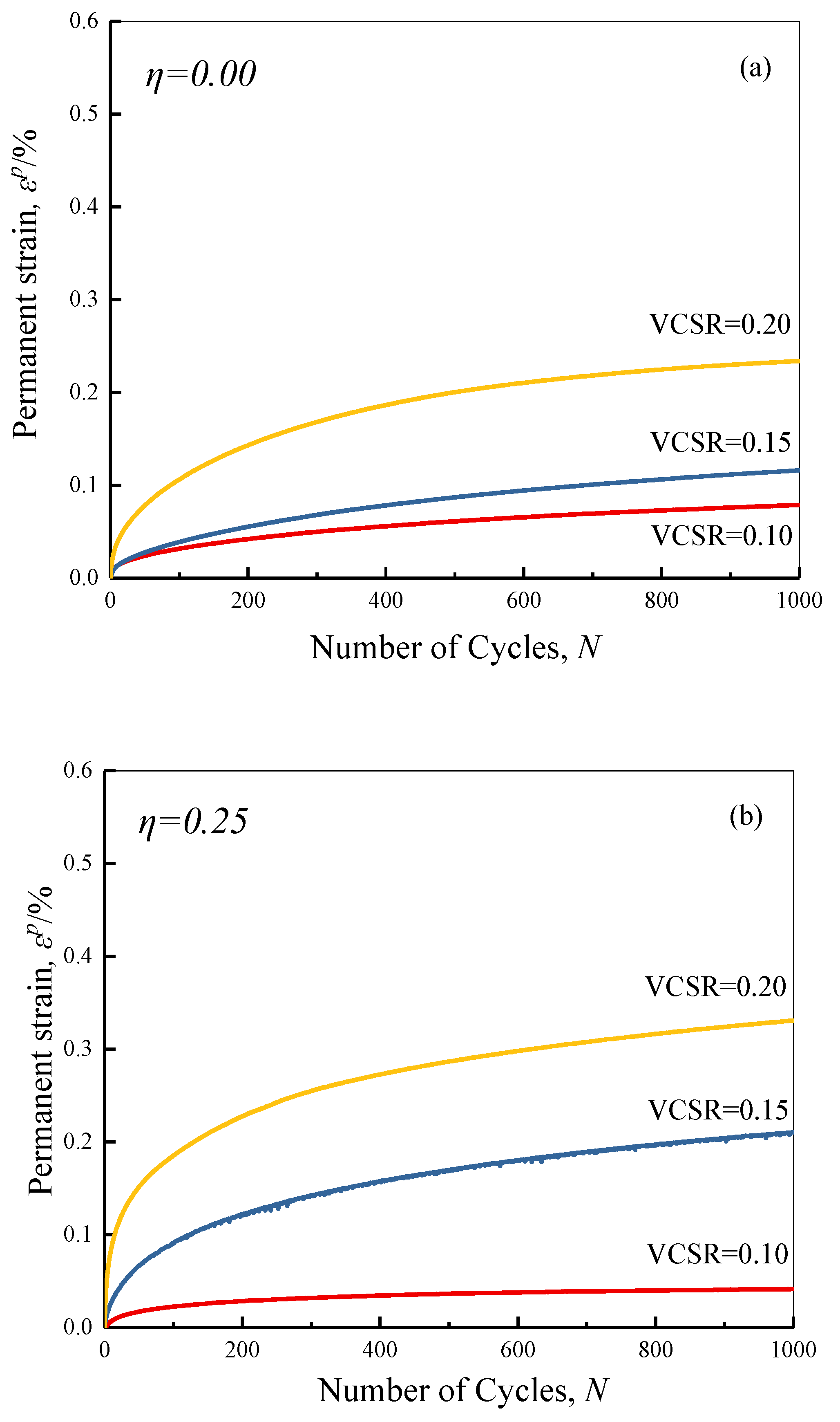
4.2. Axial Strain
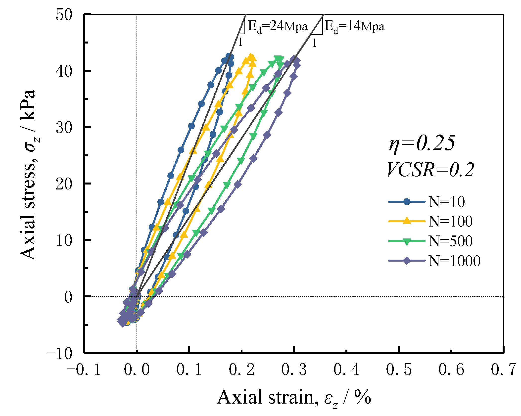
4.3. Stress–Strain Hysteresis Curve
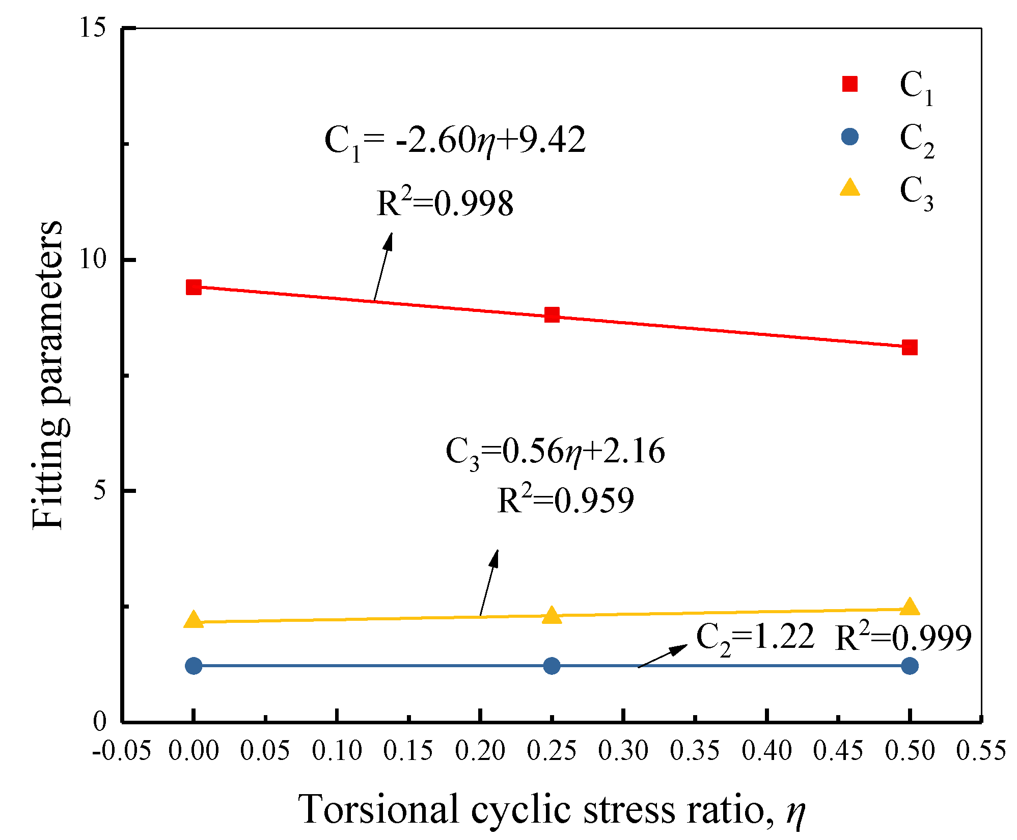
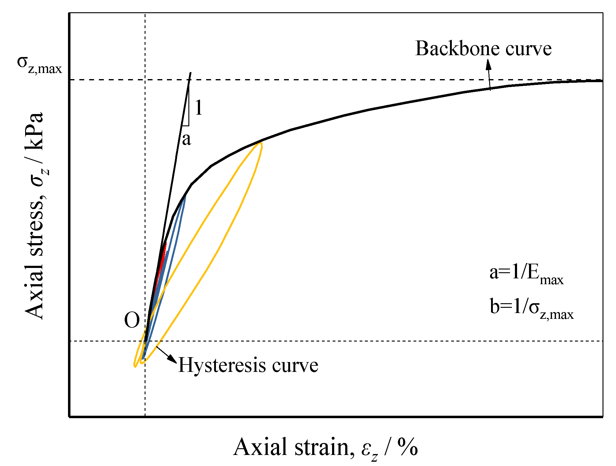
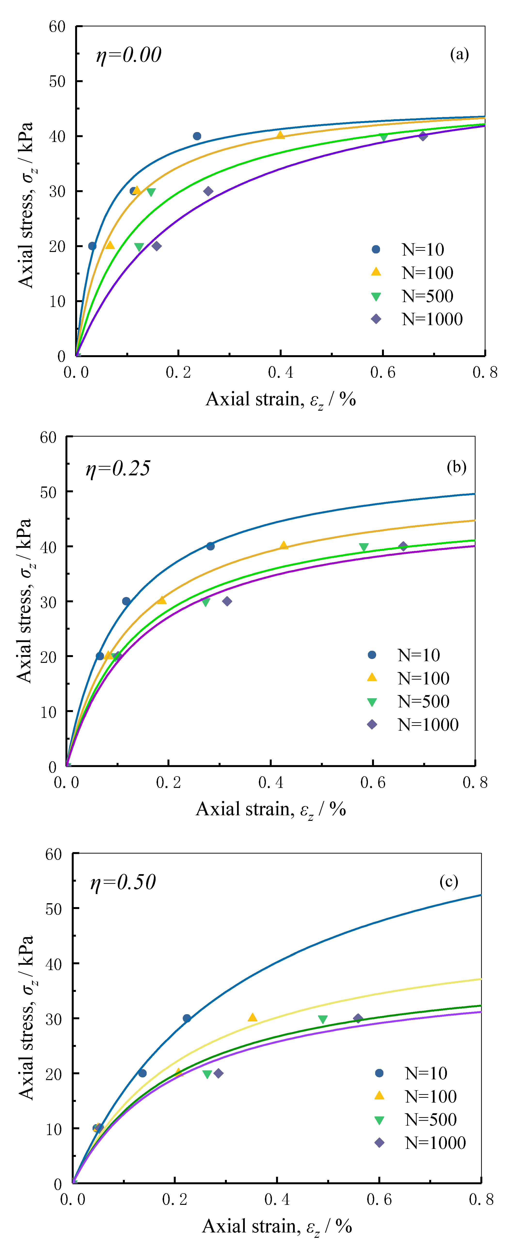
4.4. Backbone Curve
5. Conclusions
- (1)
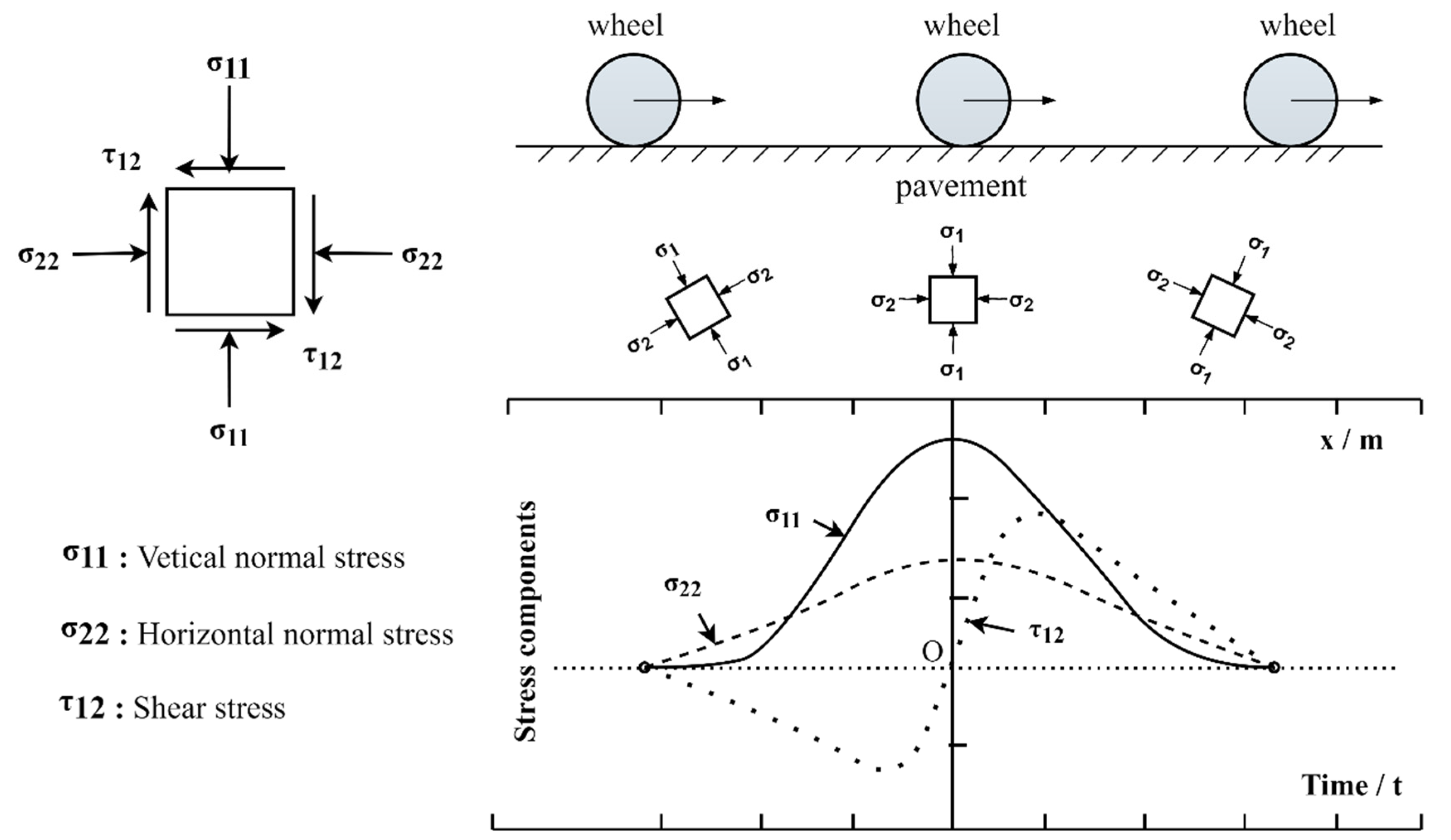
- The continuous rotation of the principal stress axis could be controlled by dynamic hollow cylinder torsional shear apparatus (DHCA) to simulate traffic loading. Compared with the traditional triaxial test without considering the principal stress rotation, the rotation of the principal stress axis would aggravate the axial deformation of soil samples. Therefore, the influence of the principal stress rotation must be considered in the prediction of settlement and stability for pavement engineering suffering traffic loading.
- (2)
- Changes in the vertical cyclic stress ratio VCSR and torsional cyclic stress ratio η had a more pronounced effect on the dynamic mechanical properties of soft clay. Under the traffic loading, the permanent strain and pore pressure increased with the increments in VCSR and η, and there was stiffness degradation of the soil.
- (3)
- A modified pore pressure model considering the rotation of the principal stress was proposed, and the relationship between the growth of pore pressure and cycles considering the effect of the principal stress rotation was established. The reasonableness of the model was confirmed by predicting the growth of the accumulated pore pressure under different cycles.
- (4)
- The permanent strain and pore pressure showed an overall increasing trend with the number of cycles, but both tended to stabilize with cycles. At the same time, the slope of the backbone curve of saturated soft clay decreased, and the stiffness of the soil decreased.
- (5)
- The traditional H–D backbone curve model without considering the continuous rotation of the principal stress axis under traffic load was modified, and the modified H-D backbone curve model considering the continuous rotation of the principal stress axis was established. Compared with the traditional H–D backbone curve model, the prediction accuracy of the modified model is significantly improved, which can provide some guidance for pavement design.
Author Contributions
Funding
Institutional Review Board Statement
Informed Consent Statement
Data Availability Statement
Conflicts of Interest
References
- Guo, L.; Wang, J.; Cai, Y.; Liu, H.; Gao, Y.; Sun, H. Undrained Deformation Behavior of Saturated Soft Clay under Long-Term Cyclic Loading. Soil Dyn. Earthq. Eng. 2013, 50, 28–37. [Google Scholar] [CrossRef]
- Skempton, A.W. The Pore-Pressure Coefficients A and B. Géotechnique 1954, 4, 143–147. [Google Scholar] [CrossRef]
- Ishikawa, T.; Sekine, E.; Miura, S. Cyclic Deformation of Granular Material Subjected to Moving-Wheel Loads. Can. Geotech. J. 2011, 48, 691–703. [Google Scholar] [CrossRef] [Green Version]
- Tang, L.; Chen, H.; Sang, H.; Zhang, S.; Zhang, J. Determination of Traffic-Load-Influenced Depths in Clayey Subsoil Based on the Shakedown Concept. Soil Dyn. Earthq. Eng. 2015, 77, 182–191. [Google Scholar] [CrossRef]
- Powrie, W.; Yang, L.A.; Clayton, C.R.I. Stress Changes in the Ground below Ballasted Railway Track during Train Passage. Proc. Inst. Mech. Eng. Part F J. Rail Rapid Transit 2007, 221, 247–262. [Google Scholar] [CrossRef]
- Sanger, F.J.; Sayles, F.H. Thermal and Rheological Computations for Artificially Frozen Ground Construction. Eng. Geol. 1979, 13, 311–337. [Google Scholar] [CrossRef]
- Shahu, J.T.; Yudhbir; Rao, N. A Simple Test Methodology for Soils under Transportation Routes. Geotechnique 1999, 49, 639–649. [Google Scholar] [CrossRef]
- Yasuhara, K.; Murakami, S.; Song, B.-W.; Yokokawa, S.; Hyde, A.F.L. Postcyclic Degradation of Strength and Stiffness for Low Plasticity Silt. J. Geotech. Geoenviron. Eng. 2003, 129, 756–769. [Google Scholar] [CrossRef]
- Dobry, R.; Vucetic, M. Dynamic Properties and Seismic Response of Soft Clay Deposits. In Proceedings of the International Symposium on Geotechnical Engineering of Soft Soils, Mexico City, Mexico, 13–14 August 1987; Volume 2, pp. 51–87. [Google Scholar]
- Stokoe, K.H., II; Hwang, S.K.; Lee, J.K.; Andrus, R.D. Effects of Various Parameters on the Stiffness and Damping of Soils at Small to Medium Strains. Pre-failure Deformation of Geomaterials. In Proceedings of the International Symposium, Sapporo, Japan, 12–14 September 1994. [Google Scholar]
- Teachavorasinskun, S.; Thongchim, P.; Lukkunaprasit, P. Stress Rate Effect on the Stiffness of a Soft Clay from Cyclic, Compression and Extension Triaxial Tests. Géotechnique 2002, 52, 51–54. [Google Scholar] [CrossRef]
- Matešić, L.; Vucetic, M. Strain-Rate Effect on Soil Secant Shear Modulus at Small Cyclic Strains. J. Geotech. Geoenviron. Eng. 2003, 129, 536–549. [Google Scholar] [CrossRef]
- Vucetic, M. Cyclic Threshold Shear Strains in Soils. J. Geotech. Eng. 1994, 32, 2208–2228. [Google Scholar] [CrossRef]
- Khosla, V.K.; Singh, R.D. Influence of Number of Cycles on Strain. Can. Geotech. J. 2011, 15, 584–592. [Google Scholar] [CrossRef]
- Paul, M.; Sahu, R.B.; Banerjee, G. Undrained Pore Pressure Prediction in Clayey Soil under Cyclic Loading. Int. J. Geomech. 2015, 15, 04014082. [Google Scholar] [CrossRef]
- Ohara, S.; Matsuda, H. Study on the Settlement of Saturated Clay Layer Induced by Cyclic Shear. Soils Found. 1988, 28, 103–113. [Google Scholar] [CrossRef] [Green Version]
- Li, T.; Meissner, H. Two-Surface Plasticity Model for Cyclic Undrained Behavior of Clays. J. Geotech. Geoenviron. Eng. 2002, 128, 613–626. [Google Scholar] [CrossRef]
- Moses, G.G.; Rao, S.N. Degradation in Cemented Marine Clay Subjected to Cyclic Compressive Loading. Mar. Georesour. Geotechnol. 2010. [Google Scholar] [CrossRef]
- Hardin, B.; Drnevich, V. Shear Modulus and Damping in Soil: Measurement and Parameter Effects. J. Soil Mech. Found. Eng. ASCE 1972, 98, 603–624. [Google Scholar] [CrossRef]
- Hardin, B.; Drnevich, V. Shear Modulus and Damping in Soils: Design Equations and Curves. J. Soil Mech. Found. Div. 1972, 98. [Google Scholar] [CrossRef]
- Ishibashi, I.; Zhang, X. Unified Dynamic Shear Moduli and Damping Ratios of Sand and Clay. Soils Found. 1993, 33, 182–191. [Google Scholar] [CrossRef] [Green Version]
- Sun, L.; Cai, Y.; Gu, C.; Wang, J.; Guo, L. Cyclic deformation behaviour of natural K0-consolidated soft clay under different stress paths. J. Cent. South Univ. 2015, 22, 4828–4836. [Google Scholar] [CrossRef]
- Pyke, R.M. Nonlinear Soil Models for Irregular Cyclic Loadings. Int. J. Rock Mech. Min. Sci. Geomech. Abstr. 1979, 16, 127. [Google Scholar] [CrossRef]
- Liao, H.J.; Tao, L.I.; Zong-Yuan, M.A.; Liu, J. Comparative Analysis of Backbone Curve Models for Loess Soils. Rock Soil Mech. 2009, 30, 17–21. [Google Scholar]
- Zhang, Y.; Kong, L.W.; Li, X.W. Dynamic Backbone Curve Model of Saturated Soft Clay under Cyclic Loading. Yantu Lixue/Rock Soil Mech. 2010, 31, 1699–1704+1708. [Google Scholar]
- Huang, J.; Chen, J.; Lu, Y.; Yi, S.; Cui, L. Deformation Behaviors and Dynamic Backbone Curve Model of Saturated Soft Clay under Bidirectional Cyclic Loading. Int. J. Geomech. 2020, 20, 04020016. [Google Scholar] [CrossRef]
- Hardin, B.O.; Kalinski, M.E. Estimating the Shear Modulus of Gravelly Soils. J. Geotech. Geoenviron. Eng. 2005, 131, 867–875. [Google Scholar] [CrossRef]
- Martin, P.P.; Boltonseed, H. One-Dimensional Dynamic Ground Response Analyses: J Geotech Engng Div ASCE, V108, NGT7, July 1982, P935–952. Int. J. Rock Mech. Min. Sci. Geomech. Abstr. 1983, 20, A9. [Google Scholar] [CrossRef]
- Lunne, T.; Berre, T.; Andersen, K.H.; Strandvik, S.; Sjursen, M. Effects of Sample Disturbance and Consolidation Procedures on Measured Shear Strength of Soft Marine Norwegian Clays. Can. Geotech. J. 2006, 43, 726–750. [Google Scholar] [CrossRef]
- Cai, Y.; Wu, T.; Guo, L.; Wang, J. Stiffness Degradation and Plastic Strain Accumulation of Clay under Cyclic Load with Principal Stress Rotation and Deviatoric Stress Variation. J. Geotech. Geoenviron. Eng. 2018, 144, 04018021. [Google Scholar] [CrossRef]
- Hight, D.W.; Symes, M.J.; Gens, A. The Development of a New Hollow Cylinder Apparatus for Investigating the Effects of Principal Stress Rotation in Soils. Geotechnique 1983, 33, 355–383. [Google Scholar] [CrossRef]
- Zhou, J.; Zhang, J.L.; Shen, Y.; Zhang, Q.F. Preparation of Hollow Cylindrical Samples of Intact Soft Clay. Chin. J. Geotech. Eng. 2007. [Google Scholar] [CrossRef]
- Ishibashi, I.; Sherif, M.A.; Student, C.T.F. Pore-Pressure Rise Mechanism and Soil Liquefaction. Soils Found. 1977, 17, 17–27. [Google Scholar] [CrossRef] [Green Version]


| Basic Properties | Value |
|---|---|
| Specific gravity Gs (g/cm3) | 2.66–2.68 |
| Natural density ρ (g/cm3) | 1.63–1.65 |
| Natural water content w (%) | 56.7–59.6 |
| Initial void ratio e0 (-) | 1.64–1.71 |
| Plasticity index Ip (%) | 42 |
| Plastic limit wp (%) | 24 |
| Liquid limit wL (%) | 66 |
| Clay content (%) | 55 |
| Silt content (%) | 41 |
| Stress | Strain | |
|---|---|---|
| Vertical | ||
| Circumferential | ||
| Radial | ||
| Shear | ||
| Major principal | ||
| Intermediate principal | ||
| Minor principal |
| Shear Cyclic Stress Level, η | Vertical Cyclic Stress Ratio, VCSR | ||
|---|---|---|---|
| Test1 | Test2 | Test3 | |
| 0.00 | 0.10 | 0.15 | 0.20 |
| 0.25 | 0.10 | 0.15 | 0.20 |
| 0.50 | 0.05 | 0.10 | 0.15 |
| No. of Cycles, N | Parameter, a | Parameter, b | R-Squared, R2 | Cyclic Shear Stress Ratio, η |
|---|---|---|---|---|
| 10 | 0.00101 | 0.0217 | 0.9462 | 0.00 |
| 100 | 0.00160 | 0.0211 | 0.9717 | |
| 500 | 0.00265 | 0.0204 | 0.8441 | |
| 1000 | 0.00439 | 0.0184 | 0.9717 | |
| 10 | 0.00199 | 0.0177 | 0.9890 | 0.25 |
| 100 | 0.00254 | 0.0192 | 0.9883 | |
| 500 | 0.00291 | 0.0207 | 0.9761 | |
| 1000 | 0.00318 | 0.0210 | 0.9647 | |
| 10 | 0.00463 | 0.0133 | 0.9860 | 0.50 |
| 100 | 0.00498 | 0.0207 | 0.9487 | |
| 500 | 0.00524 | 0.0244 | 0.9350 | |
| 1000 | 0.00543 | 0.0253 | 0.9338 |
Publisher’s Note: MDPI stays neutral with regard to jurisdictional claims in published maps and institutional affiliations. |
© 2021 by the authors. Licensee MDPI, Basel, Switzerland. This article is an open access article distributed under the terms and conditions of the Creative Commons Attribution (CC BY) license (https://creativecommons.org/licenses/by/4.0/).
Share and Cite
Fu, Z.; Wang, G.; Song, W.; Yu, Y.; Wei, P.; Wu, T. Deformation Behavior of Saturated Soft Clay under Cyclic Loading with Principal Stress Rotation. Appl. Sci. 2021, 11, 8987. https://doi.org/10.3390/app11198987
Fu Z, Wang G, Song W, Yu Y, Wei P, Wu T. Deformation Behavior of Saturated Soft Clay under Cyclic Loading with Principal Stress Rotation. Applied Sciences. 2021; 11(19):8987. https://doi.org/10.3390/app11198987
Chicago/Turabian StyleFu, Zunan, Guoshuai Wang, Wenbo Song, Yanming Yu, Pengfei Wei, and Tingyu Wu. 2021. "Deformation Behavior of Saturated Soft Clay under Cyclic Loading with Principal Stress Rotation" Applied Sciences 11, no. 19: 8987. https://doi.org/10.3390/app11198987
APA StyleFu, Z., Wang, G., Song, W., Yu, Y., Wei, P., & Wu, T. (2021). Deformation Behavior of Saturated Soft Clay under Cyclic Loading with Principal Stress Rotation. Applied Sciences, 11(19), 8987. https://doi.org/10.3390/app11198987