Abstract
In this study, a spiral groove liquid film vaporization model based on the viscosity–temperature equation, fluid internal friction, saturation temperature, and pressure relationship equation was established. Using a multiphase flow model based on the finite volume method, the influence of the change in the mass transfer coefficient on the vaporization of the liquid film was studied. Moreover, the influence law of structural parameter changes in liquid film vaporization characteristics and sealing performance was analyzed. The results indicate that, with an increase in the mass transfer coefficient, the average vapor phase volume fraction first increases and then gradually stabilizes. When calculating the average vapor phase volume fraction, it is necessary to consider the influence of the mass transfer coefficient, whereas its effect on the opening force and leakage can usually be neglected. Under the optimal mass transfer coefficient conditions, the average vapor phase volume fraction increases with an increase in the helix angle, groove-weir ratio, and groove depth. By comparison, with an increase in the groove-diameter ratio, the average vapor phase volume fraction first increases and then decreases. The opening force decreases with an increase in the helix angle, groove-to-weir ratio, and groove depth. On the other hand, it first decreases and then increases with an increase in the groove-diameter ratio. The leakage rate increases first and then stabilizes with an increase in the helix angle. Moreover, it increases continuously with an increase in the groove-diameter ratio, groove-weir ratio, and groove depth.
1. Introduction
The spiral groove mechanical seal is a typical non-contact mechanical seal. The liquid film between the end faces can not only provide opening force, but also reduce end face wear. It has been successfully applied to equipment such as pumps, steam turbines, and reactors [1]. Currently, volatile or easily vaporized liquid media are more frequently used in the fluid industry. When the pump is running, the temperature rise of the mechanical seal face causes the liquid film between the seal faces to vaporize, thus changing the seal face fluid film to a vapor–liquid mixed state [2,3].
Because the fluid film is in a two-phase state, its full sealing film stability is relatively poor. Therefore, the liquid film phase transition impacts the operational stability and reliability of the seal. The aforementioned may even result in seal failure [4]. Although the phase transition may improve the film carrying capacity, reduce leakage, and reduce interfacial friction torque, it also may cause adverse effects [5,6,7]. For example, vaporization may cause the integrity of the seal face liquid film to be damaged, thus ensuring the contact between the separated dynamic and static ring seal faces. Consequently, seal face wear, cavitation damage, seal face thermal cracking, or other forms of seal failure may occur.
Recently, numerous researchers have carried out relevant research on the phase transition of liquid film mechanical seals. The Rayleigh–Plesset equation, Zwart–Gerber–Belanri model [8], Schnerr–Sauer model [9], and Singhal model [10] have been proposed to solve the cavitation phase transition problem. To address the vaporization phase transition problem, Xu [11], Safari [12], and Li [13] have proposed different types of Thermal LB models based on the lattice Boltzmann method. The Lee model [14] is generally used for computational fluid dynamics (CFD) analyses to simulate the condensation or the boiling process. This model has the advantages of a simple form, relatively easy calculation, and high reliability. Chen et al. [15,16,17] established a vaporization phase transition calculation model based on the viscosity–temperature effect. The saturation temperature with the pressure change equation, fluid internal friction effect, and the phase transition mechanism of the spiral groove liquid film seal were analyzed and discussed. The effect of operating condition parameters on vaporization characteristics of the liquid film and the sealing performance parameters were studied. Based on the evaporation and condensation model in Fluent, Shi [18] and Liu [19] analyzed and calculated the vaporization distribution law of the seal surface liquid film and the phase transition radius. Cao [20,21,22], Wang [23,24], and Ma [25] established the spiral groove and other liquid film phase transition models. Moreover, the authors calculated the flow field and seal pressure distribution in the sealing gap. In addition, they analyzed the influence of operating conditions and structural parameters on the phase transition of the liquid film. Finally, the authors studied the influence of the phase change area on the sealing performance. Based on the finite volume method, Gao [26] established a fluid model to analyze and study the coexistence of cavitation and vaporization.
However, in related studies, the mass transfer equation in the Lee model has a mass transfer coefficient whose value is usually based on the researcher’s experience. This value lacks a theoretical basis, and the values in different documents are inconsistent [27,28,29]. The mass transfer coefficient is generally taken as a default value when studying the phase transition of a non-contact mechanical seal liquid film. Qiu et al. [30] proposed that when CFD is used to simulate the vaporization phase transition, a larger value can be selected for the mass transfer coefficient. The larger the value, the higher the calculation accuracy. Moreover, the value of the mass transfer coefficient is not as large as possible, and there is an optimal value that can meet the calculation accuracy and calculation cost. In the current study, the upstream pumping mechanical seal of the spiral groove was used for the geometric model. Based on this model, a liquid film vaporization calculation model based on the viscosity–temperature equation, fluid internal friction, saturation temperature, and pressure relationship equation was established. Moreover, the effect of different mass transfer coefficients on the phase transition of the liquid film in the Mixture model in Fluent was analyzed and calculated. Finally, the effect of the change in structural parameters of the groove on the phase transition of the liquid film and the sealing performance under the condition of the optimal mass transfer coefficient was studied.
2. Establishing the Model
As shown in Figure 1, , , and respectively represent the outer radius, the inner radius, and the groove root radius of the end face of the moving ring. Parameters and respectively represent the angle of the spiral groove area and the weir area corresponding to the center of the circle. Parameter represents the helix angle, which is defined as the angle between the tangent of any point on the helix and the tangent on the circle where it is located. The following definitions are introduced for simplicity: groove-diameter ratio , groove-weir ratio .
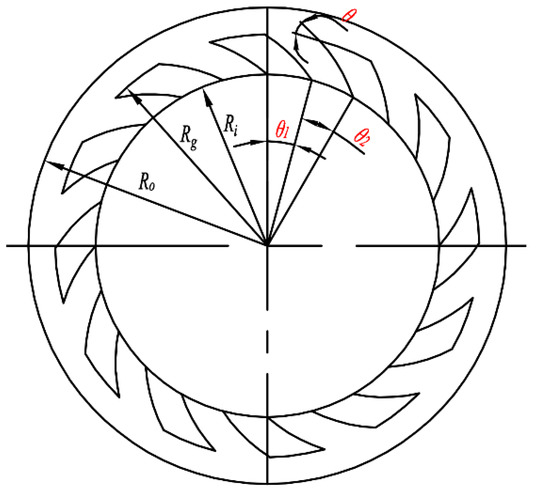
Figure 1.
Structure of end face of rotating seal ring.
The phase transition mechanism of the spiral groove liquid film seal is relatively complicated. For simplicity purposes, the following assumptions are made [31]:
- (1)
- The fluid medium is a Newtonian fluid.
- (2)
- The fluid flow between the sealing interfaces is continuous medium laminar, and the fluid temperature and viscosity do not change with time.
- (3)
- The sealing surface is smooth, i.e., the effect of its roughness on the fluid flow is assumed to be negligible.
- (4)
- The film thickness is very thin, and the pressure and density remain unchanged in the thickness direction.
- (5)
- The temperature of the sealing ring and the mechanical properties of the material do not change with time.
- (6)
- There is no relative slip between the fluid medium and the seal face.
- (7)
- Disturbance and vibration of the system during operation are not accounted for.
Lee et al. [14] established independent conservation equations for the liquid and vapor phases. Evaporation and condensation terms of the mass transfer equation are shown respectively in Equations (1) and (2):
In Equations (1) and (2), Tsat represents the evaporation temperature, and λc is the phase transition mass transfer coefficient, which can be experimentally obtained. The subscripts l and v indicate liquid phase and vapor phase, respectively. Finally, and represent the volume fraction and density, respectively.
The phase transition mass transfer coefficient λc can be expressed as [32]:
where d is the bubble diameter, is the adjustment coefficient, M is the molar mass, R is the general gas constant, hfg is the latent heat of vaporization, Ts is the fluid saturation temperature, and and are density of liquid and vapor phase.
After the phase transition of the liquid film, the entire fluid film transforms into a homogeneous mixture made up of liquid and vapor. According to Wallis et al. [33], Equation (4) can accurately explain the relationship between the density and viscosity of the mixture:
where and are the dynamic viscosities of the vapor and liquid phases, respectively, and is the mass fraction of the vapor phase in the mixed phase.
Temperature not only affects the degree of liquid film phase transition, but also affects the viscosity of the liquid phase in the liquid film and the saturated vapor pressure of the sealing medium. Because the viscosity of the vapor phase is much smaller than that of the liquid phase and is less affected by the temperature, its effect can be assumed to be negligible. In this study, the sealing medium is liquid water, and the vapor phase viscosity is the viscosity of water vapor at the corresponding temperature. The relationship between the viscosity of liquid water and the temperature, and the relationship between the saturated vapor pressure of water and the temperature, can be obtained from [34].
3. Solution Settings
3.1. Computational Domain Geometry Model
According to Figure 1, the spiral grooves are periodically distributed along the circumferential direction on the end face of the moving ring. Moreover, it can be considered that the flow field motion state of each groove area and each weir area is the same. To improve the computational efficiency, one of the grooves is taken as the computational domain (Figure 2). The saturation temperature curve equation and viscosity–temperature equation are compiled and loaded into Fluent through user-defined functions in the Fluent software.
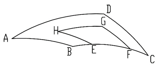
Figure 2.
Computational domain geometry model.
3.2. Meshing
A hexahedral structure mesh is employed within the ICEM module in ANSYS 19.0 to divide the computational domain. Because the groove depth and film thickness of the model are measured in micrometers, they are several orders of magnitude different from the other size parameters of the model. To meet the calculation accuracy requirements, the block function is used to divide the calculation domain into a spiral groove area and a liquid film area. Then, nodes on the boundary of each area are defined to ensure that the overall mesh quality is satisfactory [35].
To achieve the required calculation accuracy and reduce the calculation cost, the opening force of the seal face was compared and analyzed for the following number of grids: 79,749, 146,397, 257,420, 367,819, and 577,060. When the number of grids was 367,819, the relative error was 0.12%. Furthermore, considering the influence of the number of grids on the calculation cost, it was decided to divide the grid with the size of grids as the standard.
3.3. Boundary Conditions and Solver Settings
The boundary conditions of the calculation domain were set according to Table 1.

Table 1.
Boundary condition settings.
Control equations were discretized based on the finite volume method, and a double-precision, pressure-based solver was chosen. The Mixture model was chosen for the multi-flow model. The evaporation–condensation model was chosen for the phase change model. Mass transfer coefficients were selected as 0.1, 2, 4, 6, 48. It should be mentioned that a higher mass transfer coefficient can obtain a higher precision result. However, the calculation cost requires that a smaller mass transfer coefficient is selected while ensuring sufficient accuracy. The SIMPLEC algorithm was selected, and the PRESTO! format was selected for pressure discrete items. A second-order upwind style was chosen for the momentum and energy items. A first-order upwind style was chosen for the volume fraction. The pressure relaxation factor was set to 0.3, and convergence accuracy was set to 10−6.
4. Model Validation
To verify the rationality of the model, the phase transition simulation calculation results of the spiral groove liquid film seal were compared with the results from [21], and the comparison is shown in Figure 3. The average vapor phase volume fraction calculated via default mass transfer coefficient (0.1) in this paper is consistent with the results obtained from the literature. Moreover, the overall agreement is high, which verifies the accuracy of the simulation results. However, under the same conditions, when the mass transfer coefficient was set to 2, 4, or 6, the calculated average vapor phase volume fraction increases from the original 3% to 25%, 32%, and 36%, respectively. This shows that the results obtained using the default mass transfer coefficient are not credible. Therefore, corresponding research and analysis on the influence of the change in the mass transfer coefficient on the average vapor phase volume fraction were conducted in this study. The corresponding simulation calculation was carried out by setting the mass transfer coefficient to 6, 18, 24, 30 … 300. The calculation results are shown in Figure 4.
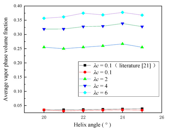
Figure 3.
Variation of average vapor volume fraction with helix angle under different mass transfer coefficients.
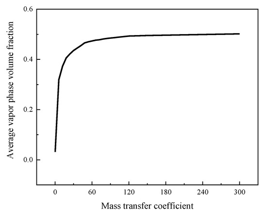
Figure 4.
Variation curve of average vapor phase volume fraction with mass transfer coefficient.
Based on the data provided in Figure 4, with an increase in the mass transfer coefficient, the average vapor phase volume fraction rapidly increases until it reaches the value of 0.47. Then, between 0.47 and 0.5, slow growth is observed and eventually stabilizes. This indicates that the calculated value of the average vapor phase volume fraction increases with the mass transfer coefficient. Furthermore, the larger the mass transfer coefficient, the more similar the obtained value to the actual results, which is consistent with the conclusion obtained in [29]. After the mass transfer coefficient was set to 48, the average vapor phase volume fraction calculated each time had a growth rate of less than 1% compared with the previous calculation result. Considering the calculation efficiency and cost issues, 48 was selected as the mass transfer coefficient for the simulation calculation in this study.
5. Result Analysis
The performance of dynamic pressure sealing is judged by the average vapor phase volume fraction , opening force F, and leakage rate Q. Considering that the change in working condition parameters affects the aforementioned sealing performance parameters, the pressure inlet is taken as = 1 MPa, the inlet temperature is = 393 K, the pressure outlet is the standard atmospheric pressure, the outlet temperature is = 300 K (ambient temperature), the speed n = 3000 rpm, the number of grooves is 12, the seal face outer diameter is = 31 mm, and the inner diameter is = 26 mm. The variation range of other parameters is shown in Table 2.
Table 2.
Parameter range.
5.1. Effect of Helix Angle on Sealing Performance
Based on Figure 5a,b for λc = 48, when the spiral groove θ is in the range of 20 to 30°, the average vapor phase volume fraction increases with an increase in the spiral angle θ. In addition, the opening force gradually decreases with an increase in the spiral angle θ. An increase in the helix angle θ leads to the reduction in the working surface area on the leeward side of the spiral groove. Furthermore, a sudden and simultaneous increase in the pressure gradually decreases the low-pressure zone of the groove. However, its area gradually increases, which continuously increases the vaporization phase transition area. Consequently, this leads to a decrease in the opening force between the two seal faces and an increase in the average vapor phase volume fraction. On the contrary, the opening force decreases continuously with an increase in the phase change. This, however, is inconsistent with the enhancement of the lifting ability of the phase change to the opening force mentioned in [21]. According to Figure 5c, with an increase in the helix angle θ, the leakage rate has a certain change, and first increases and then stabilizes. However, the magnitude of this change is negligible compared to the change in leakage caused by other structural parameters.
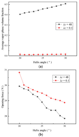
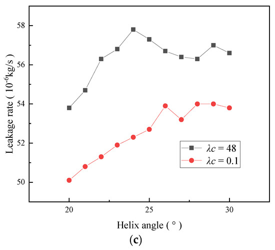
Figure 5.
Effect of helix angle on sealing performance. (a) Effect on the average vapor phase volume fraction. (b) Effect on the opening force. (c) Effect on the leakage rate.
When λc = 0.1, the average vapor phase volume fraction is relatively small, and the change in the helix angle has almost no effect on its value. This observation is significantly different from the obtained results when λc = 48. However, the variation of the opening force and the leakage rate with the helix angle is approximately the same as when λc = 48. The maximum error of the opening force is 3.7%, which is almost negligible, and the leakage is reduced by 3.7 to 9.6%.
5.2. Effect of the Groove-Diameter Ratio on Sealing Performance
When λc = 48, the average vapor phase volume fraction in Figure 6a first increases and then decreases with an increase in the groove-diameter ratio. The maximum value is reached when the groove-diameter ratio is 0.5. According to Figure 6b, with an increase in the groove-diameter ratio, the opening force first decreases and then increases. The minimum value is obtained when the groove-diameter ratio is 0.7. Based on Figure 6c, the leakage rate increases continuously with an increase in the groove-diameter ratio. When the groove-diameter ratio is relatively small, the working surface area on the leeward side of the spiral groove decreases, the sudden change area of the pressure is smaller, and the low-pressure area is not obvious in the entire liquid film. Furthermore, the degree of phase change decreases, the average vapor phase volume fraction decreases, and the opening force increases. With a gradual increase in the groove diameter ratio, the area of the working face on the leeward side of the spiral groove, the range of the low-pressure area, and the degree of phase change all increase. However, the area of the working surface on the windward side of the spiral groove also increases, thus making the dynamic pressure effect more obvious. When generating a groove-diameter ratio of 0.5, the dynamic pressure effect on the inhibition of the spiral groove area exceeds the low-pressure phase transition region. Therefore, the occurrence of the phase transition is effectively suppressed, thus resulting in a significant reduction in the average volume fraction of the vapor phase. Similarly, when the groove-diameter ratio is 0.7, the effect of dynamic pressure on the opening force of the end face is more evident than the effect of reducing it in the low-pressure area. Therefore, the opening force increases with an increase in the groove-diameter ratio. The increase in the groove-diameter ratio leads to a continuous increase in the spiral groove area and a continuous enhancement in pumping capacity. Consequently, the leakage rate presents an increasing trend.
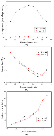
Figure 6.
Effect of groove-diameter ratio on sealing performance. (a) Effect on the average vapor phase volume fraction. (b) Effect on the opening force. (c) Effect on leakage rate.
When λc = 0.1, the average vapor phase volume fraction, opening force, and leakage rate are almost equal to the groove-diameter ratio. However, the average vapor phase volume fraction is significantly affected by λc, and the average vapor phase volume fraction at 0.1 is insignificant. Finally, the opening force and the leakage rate vary within the same interval.
5.3. Effect of the Groove-Weir Ratio on Sealing Performance
According to Figure 7, when λc = 48, the average vapor phase volume fraction and leakage rate both increase with an increase in the groove-weir ratio, whereas the opening force decreases with an increase in the groove-weir ratio. When the groove-weir ratio is 0.1, a larger weir area between the two periodic spiral grooves exists, and the groove area is smaller. Therefore, the low-pressure area is formed when the liquid film flow decreases. Moreover, the phase transition area decreases, thus resulting in a lower average vapor phase volume fraction and a higher opening force. As the groove-weir ratio increases, the area occupied by the weir area in the two periods gradually decreases, whereas the groove area gradually increases. Therefore, both the low-pressure area of the liquid film and the phase transition area increase. The average vapor phase volume fraction increases and the opening force decreases. When the groove-weir ratio is 0.9, the weir area between two periodic spiral grooves is the smallest, the groove area and the low-pressure area are the largest, and the degree of phase transition is the highest. The average vapor phase volume fraction increases to the maximum value and the opening force decreases to the minimum value. With an increase in the groove-weir ratio, the exit area of the spiral groove continues to increase. Moreover, the leakage reduction effect continues to decrease, thus resulting in a continuous increase in the leakage rate.
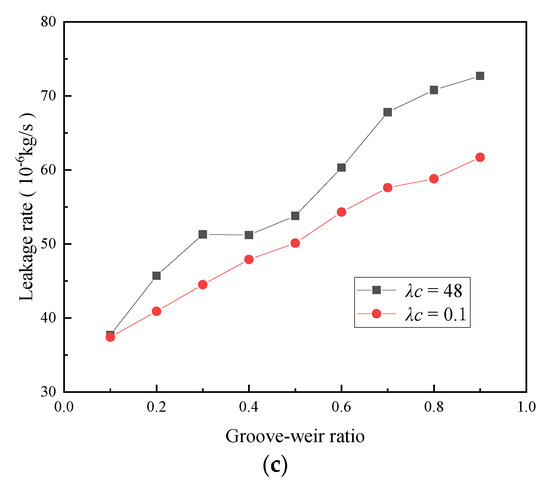
Figure 7.
Effect of groove-weir ratio on sealing performance. (a) Effect on the average vapor phase volume fraction. (b) Effect on the opening force. (c) Effect on leakage rate.
When λc = 0.1, with an increase in the groove-weir ratio, the average vapor phase volume fraction and the leakage rate both increase, and the opening force decreases accordingly. Compared with the case when λc = 48, the variation range of the average vapor phase volume fraction is much smaller, and the variation range of the opening force remains unchanged. An increase in leakage rate has gradually decreased, and the relative error has increased from 0.5% to 14%.
5.4. Effect of Groove Depth on Sealing Performance
When λc = 48, it can be seen from Figure 8a,b that, as the groove depth increases, the average vapor phase volume fraction increases while the opening force decreases. As the depth of the spiral groove increases, the height difference on the leeward side of the spiral groove continues to increase. Consequently, this increases the degree of a sudden change in the pressure of the liquid film. The low-pressure area gradually spreads, and the degree of phase transition gradually increases. This causes the average vapor phase volume fraction to gradually increase and the opening force to continuously decrease. According to Figure 8c, the leakage rate increases with the groove depth. When λc = 0.1, as the groove depth increases, the volume fraction remains unchanged. Moreover, the opening force decreases as the groove depth increases. In addition, the leakage rate increases with an increase in the groove depth. However, the degree of change is lower when compared to the case when λc = 48. The effect of helix angle and groove depth on the leakage rate is much smaller than the effect of the groove-diameter ratio and groove-weir ratio.
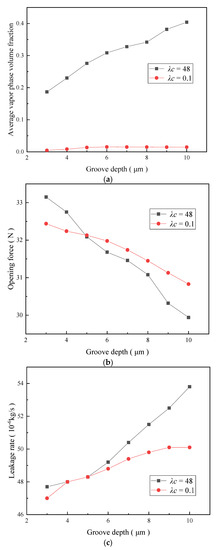
Figure 8.
Effect of groove depth on sealing performance. (a) Effect on the average vapor phase volume fraction. (b) Effect on the opening force. (c) Effect on leakage rate.
6. Conclusions
Based on the model established in this study, the influence of the mass transfer coefficient on the phase transition of the liquid film was calculated and analyzed. According to the optimized mass transfer coefficient, the influence of the spiral seal face groove structural parameters on the performance of the liquid film seal between the seal faces was calculated and analyzed. The following conclusions were obtained:
- (1)
- The phase transition phenomenon of the spiral groove liquid film seal was simulated and calculated. Based on the calculation results, as the mass transfer coefficient increases, the average vapor phase volume fraction first increases and then stabilizes. The average vapor phase volume fraction changes in the same manner under different mass transfer coefficients. However, the difference between the calculated values is obvious, and the influence of the mass transfer coefficient cannot be ignored. However, the effect of the change in the mass transfer coefficient on the opening force and the leakage rate can be assumed to be negligible. Therefore, when performing the numerical analysis of the average vapor phase volume fraction simulation, it is necessary to determine the mass transfer coefficient before performing the subsequent calculation and analysis.
- (2)
- The average vapor phase volume fraction increases with an increase in the helix angle, groove-weir ratio, and groove depth. Moreover, the average vapor phase volume fraction first increases and then decreases with an increase in the groove-diameter ratio. The opening force decreases with an increase in the helix angle, groove-weir ratio, and groove depth. By comparison, the opening force first decreases and then increases with an increase in the groove-diameter ratio. The leakage rate first increases and then stabilizes with an increase in the helix angle. Moreover, the leakage rate increases continuously with an increase in the groove-diameter ratio, groove-weir ratio, and groove depth. The effect of the helix angle and the groove depth on the leakage rate is less obvious than the effect of the groove-diameter ratio and groove-weir ratio. As such, it can be assumed to be negligible.
- (3)
- This paper represents an analysis of the influence of single-factor structural parameters based on the optimal mass transfer coefficient on the phase transition of the spiral groove mechanical seal liquid film. In future works, the influence of structural parameters on the phase transition of the liquid film under the interaction of multiple factors will be discussed. Moreover, the effect of changes in operating conditions on the phase transition and sealing performance parameters will also be investigated.
- (4)
- The current study of the influence of the change in the mass transfer coefficient on the vaporization of liquid film fills an existing research gap. It has important theoretical and engineering significance for the design and application of mechanical seals with different structural parameters, controlling the degree of phase change, improving the sealing stability, and improving the sealing performance.
Author Contributions
C.M., X.X. and Y.Z. outlined the structure of the paper, X.X. wrote the paper, Y.Z., J.S. and Q.Y. revised the paper. All authors have read and agreed to the published version of the manuscript.
Funding
This research was funded by the National Key R&D Program of China (No. 2018YFB2000800), the National Natural Science Foundation of China (No. 52075268), and the Key R&D Program of Jiangsu Province (No. BE2021062).
Acknowledgments
The authors acknowledge the financial support provided by the National Key R&D Program of China (No. 2018YFB2000800), the National Natural Science Foundation of China (No. 52075268), and the Key R&D Program of Jiangsu Province (No. BE2021062).
Conflicts of Interest
The authors declare no conflict of interest.
References
- Du, P. Research and progress of mechanical seals operating with vaporization transition. Eng. Technol. Mag. 2016, 12, 224. [Google Scholar]
- Yang, X.; Meng, X.K.; Peng, X.D. A TEHD lubrication analysis of surface textured mechanical seals. Tribology 2018, 38, 204–212. [Google Scholar]
- Li, F.C.; Wang, Y.L.; Liu, J.; Ding, S.Y.; Xiang, L.I. Analysis and study on failure mechanism of mechanical seals in running. Hydraul. Pneum. Seals 2019, 39, 46–49. [Google Scholar]
- Zhang, X.; Shi, J.; Wang, S.; Zhang, C.; Tomovic, M. Leakage model and failure factors analysis of mechanical seals. In Proceedings of the 2016 IEEE 11th Conference on Industrial Electronics and Applications (ICIEA), Hefei, China, 5–7 June 2016. [Google Scholar]
- Chen, H.L.; Wu, Q.B.; Zuo, M.Z.; Cheng, X.; Ji, H.; Li, S. Overview on liquid film cavitation in mechanical seal faces. J. Drain. Irrig. Mach. Eng. 2015, 33, 138–144. [Google Scholar]
- Song, W.; Wang, C.; Wei, Y.; Xu, H.; Lu, J. Experimental research on drag reduction characteristics of underwater vehicle during pitching. Acta Armamentarii 2019, 40, 1902–1910. [Google Scholar]
- Peng, X.D.; Jin, J.; Meng, X.K.; Jiang, J.B.; Zhao, W.J.; Li, J.Y. Research progress on the liquid face seal of vapor-liquid Two-Phase flow. Tribology 2019, 39, 643–655. [Google Scholar]
- Zwart, P.J.; Gerber, A.G.; Belamri, T. A two-phase flow model for predicting cavitation dynamics. In Proceedings of the 5th International Conference on Multiphase Flow, Yokohama, Japan, 30 May–4 June 2004. [Google Scholar]
- Habil, S.I. Physical and numerical modeling of unsteady cavitation dynamics. In Proceedings of the 4th International Conference on Multiphase Flow, New Orleans, LA, USA, 27 May–1 June 2001. [Google Scholar]
- Singhal, A.K.; Athavale, M.M.; Li, H.Y. Mathematical basis and validation of the full cavitation model. J. Fluids Eng. 2002, 124, 617–624. [Google Scholar] [CrossRef]
- Xu, A.; Shyy, W.; Zhao, T. Lattice Boltzmann modeling of transport phenomena in fuel cells and flow batteries. Acta Mech. Sin. 2017, 33, 555–574. [Google Scholar] [CrossRef]
- Safari, H.; Rahimian, M.H.; Krafczyk, M. Consistent simulation of droplet evaporation based on the phase-field multiphase lattice Boltzmann method. Phys. Rev. E Stat. Nonlinear Soft Matter Phys. 2014, 90, 033305. [Google Scholar] [CrossRef] [PubMed]
- Li, Q.; Kang, Q.; Francois, M.; He, Y.; Luo, K. Lattice Boltzmann modeling of boiling heat transfer: The boiling curve and the effects of wettability. Int. J. Heat Mass Transf. 2015, 85, 787–796. [Google Scholar] [CrossRef] [Green Version]
- Lee, W.H. Pressure iteration scheme for Two-Phase flow modeling. In Multiphase Transport Fundamentals, Reactor Safety, Applications; Hemisphere Publishing: Washington, DC, USA, 1980. [Google Scholar]
- Chen, H.; Wang, B.; Ren, K.; Li, T.; Zhao, B. Influence of cavitation thermal effect on lubrication properties of upstream pumping mechanical seal. CIESC J. 2016, 67, 4334–4343. [Google Scholar]
- Chen, H.L.; Han, T.; Li, X.W.; Lu, J.C.; Xie, X.F. Analysis of internal friction and viscosity-temperature effect on vaporization and properties of sealing liquid film. J. Jiangsu Univ. (Nat. Sci. Ed.) 2020, 41, 661–669. [Google Scholar]
- Chen, H.; Gui, K.; Li, X.; Han, T.; Xie, X.; Lu, J. Influence of operating parameters on vaporization characteristics and properties of liquid film of mechanical seal. China Mech. Eng. 2021, 32, 2–11. [Google Scholar] [CrossRef] [Green Version]
- Shi, J.X. Analysis of Mechanical Seal Phase Transition Radisu and Temperature; Beijing University of Chemical Technology: Beijing, China, 2013. [Google Scholar]
- Liu, H.H. Study on Performance of End Face Seals Used in the Condition of Low Temperature and Easily Vaporized Liquid Medium; Beijing University of Chemical Technology: Beijing, China, 2014. [Google Scholar]
- Cao, H.; Hao, M.; Li, Z.; Yang, W.; Sun, Z.; Wang, Y.; Ren, F. Effect of phase change on performance of spiral groove liquid film seals. CIESC J. 2017, 68, 3190–3201. [Google Scholar]
- Cao, H.; Hao, M.; Li, Z.; Yang, W.; Wang, Y.; Yuan, J. Performance analysis of internal pressure type spiral groove liquid film seals based on phase change. CIESC J. 2017, 68, 3532–3540. [Google Scholar]
- Cao, H.; Hao, M.; Yang, W.; Wang, Y.; Li, Y.; Xu, L. Phase change phenomenon and properties of double spiral groove liquid film seals. CIESC J. 2018, 69, 2110–2119. [Google Scholar]
- Wang, X.; Shi, L.; Huang, W.; Wang, X. A Multi-Objective optimization approach on spiral grooves for gas mechanical seals. J. Tribol. 2018, 140, 041701. [Google Scholar] [CrossRef]
- Wang, X.; Shi, L.; Huang, W.; Wang, X. Closure to Discussion of “A Multi-Objective optimization approach on spiral grooves for gas mechanical seals” (X. Wang, L. Shi, W. Huang, and X. Wang, 2018, ASME J. Tribol., 140(4), p. 041701). J. Tribol. 2019, 141, 026001. [Google Scholar] [CrossRef]
- Ma, R.M.; Feng, R.P.; Li, S.X.; Wang, J.X.; Liu, Z.W.; Song, R.L. Optimum analysis of vaporization and phase change performance of spiral groove hydrodynamic seal liquid film. J. Mech. Electr. Eng. 2020, 37, 999–1005. [Google Scholar]
- Gao, W.; Huang, W.; Wang, T.; Liu, Y.; Wang, Z.; Wang, Y. Numerical model of two-phase mechanical face seal with shallow grooves based on finite volume method. Ind. Lubr. Tribol. 2020, 72, 1303–1309. [Google Scholar] [CrossRef]
- Da, E.R.; Del, D.C. Numerical simulation of laminar liquid film condensation in a horizontal circular minichannel. J. Heat Transf. -Trans. of the ASME 2012, 134, 1–8. [Google Scholar]
- Yang, Z.; Peng, X.F.; Ye, P. Numerical and experimental investigation of two phase flow during boiling in a coiled tube. Int. J. Heat Mass Transf. 2008, 51, 1003–1016. [Google Scholar] [CrossRef]
- Zhu, Z.; Li, J.; Peng, H.; Liu, D. Nature-Inspired Structures Applied in Heat Transfer Enhancement and Drag Reduction. Micromachines 2021, 12, 656. [Google Scholar] [CrossRef] [PubMed]
- Qiu, G.D.; Cai, W.H.; Wu, Z.Y.; Jiang, Y.; Yao, Y. Analysis on the value of coefficient of mass transfer with phase change in Lee’s equation. J. Harbin Inst. Technol. 2014, 46, 15–19. [Google Scholar]
- Li, Y.; Song, P.Y.; Xu, H.J. Performance analyses of the spiral groove dry gas seal with inner annular groove. Appl. Mech. Mater. 2013, 420, 51–55. [Google Scholar] [CrossRef]
- ANSYS Inc. ANSYS14. 0 FLUENT Theory Guid; ANSYS Inc.: Canonsburg, PA, USA, 2011. [Google Scholar]
- Wallis, G.B. One-Dimensional Two-Phase Flow; McGraw-Hill Companies: New York, NY, USA, 1969. [Google Scholar]
- Li, X.W. Research on Vaporization Characteristics of Fluid Film and Performance in Hydrodynamic Mechanical Seals; Jiangsu University: Zhenjiang, China, 2019. [Google Scholar]
- Hu, K.; Li, Z.B. ANSYS ICEM CFD Engineering Examples in Detail; POSTS & TELECOM PRESS: Beijing, China, 2014. [Google Scholar]
Publisher’s Note: MDPI stays neutral with regard to jurisdictional claims in published maps and institutional affiliations. |
© 2021 by the authors. Licensee MDPI, Basel, Switzerland. This article is an open access article distributed under the terms and conditions of the Creative Commons Attribution (CC BY) license (https://creativecommons.org/licenses/by/4.0/).